Week 8 - Challenge 4 - Coin Holder Design
COIN HOLDER
AIM:
To create the centre console coin holder plastic component through the given class a surface and at the end performing the draft analysis on the model.
OBJECTIVE:
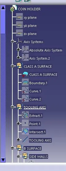
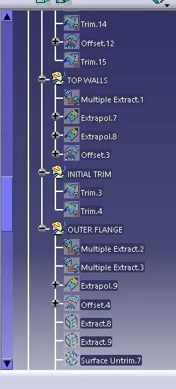
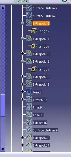
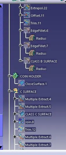
- To ensure proper tree structure is followed. Geometrical sets should have a proper name based on the sketches present inside of them.
- All the sketches should be created under the geometrical set. Use of the close surface feature to make a solid body from the surface.
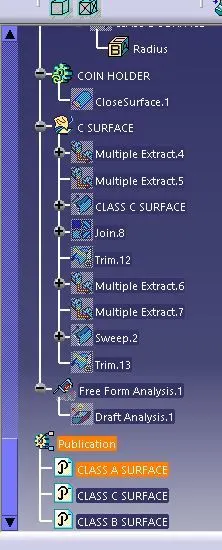
- To publish the tooling axis, class A, B and C surface.
PROCEDURE:
- First import the class A surface of the centre console coin holder model in CATIA V5.
- Check the connectivity of the class A surface using the boundary option. Ensure that there is no gap between the two surfaces.
TOOLING AXIS:
- Now we need to create the tooling axis for the centre console coin holder model.
- Visually check which direction is better for creating the tooling axis.
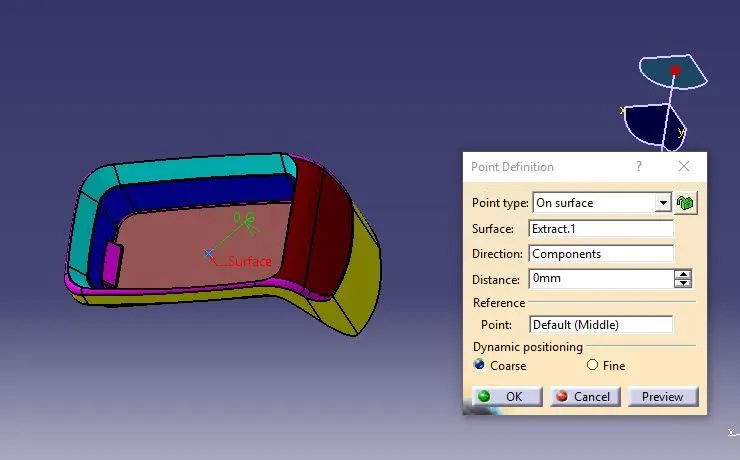
- Now to create the tooling axis in the z-direction, first create a reference point on any surface as shown below figure.
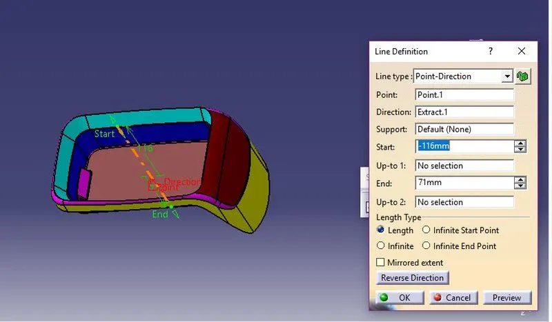
- Now using the reference point, create a line normal to the surface. This line will give us the tooling axis.
CLASS B SURFACE:
- Consider the thickness of the component as 2.5mm.
- Now we need to create a B surface that will be similar to the A surface at an offset value of 2.5mm. In this operation, we are creating A class B surface in 4 different geometrical sets.
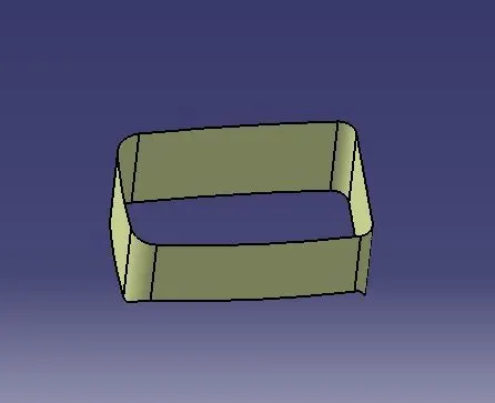
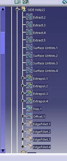
- First, we are creating a sidewall. To create this surface, we need to extract the class A surface as shown below in the below figure.
- Once the surface is extracted, untrim it and then extrapolate it by a required value on each side using point continuity.
- Trim them to form proper walls. Now offset it by 2.5mm.
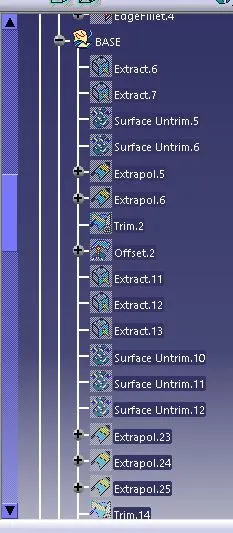
- Similarly, we need to extract the base, top wall and outer flange surface of the centre console coin holder in different geometrical sets and perform similar operations on it as mentioned above.
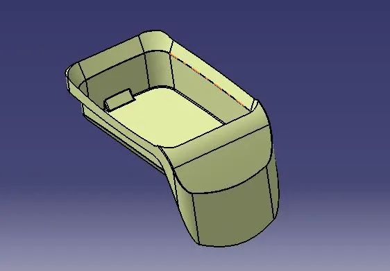
- Once all the surfaces are created trim these surfaces to form a class B surface. Give the appropriate fillets to form a class B surface.
CLASS C SURFACE:
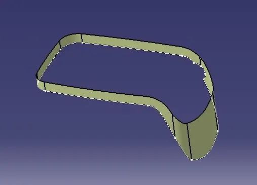
- To create a class C surface, first, extract the boundaries of the class A surface and extract the adjacent surfaces to the boundary as shown in the figure below.
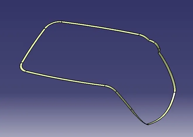
- Now using the sweep option create the surface.
- To perform this operation, Go to the toolbar > sweep > profile type > line > subtype > with reference surface > guide curve 1 – (select the extracted boundaries) > reference surface – (select the extracted surface) > angle and length as 90 deg and 4mm respectively and click ok.
TRIM SURFACE:
- After the creation of class A, class B and class C surfaces, we need to trim class B and class C surfaces to form a new surface.
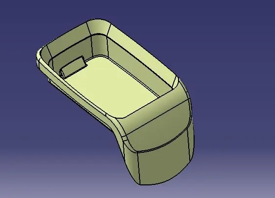
- Then join the trimmed surface with the class A surface to form the final required surface. Now using the close surface option from the part workbench form a solid body from the surface body.
DRAFT ANALYSIS
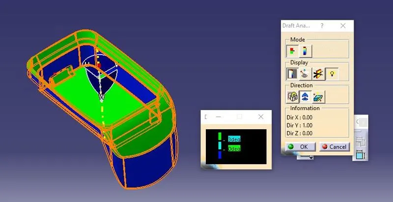
- To perform draft analysis on the centre console coin holder model, first set the view parameters to material mode.
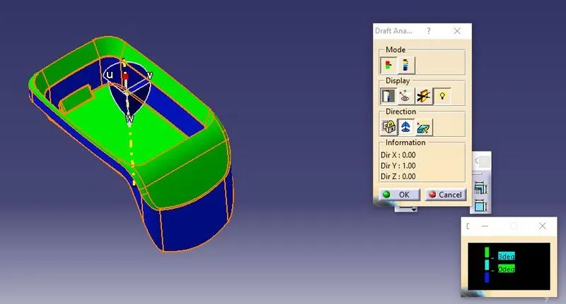
- Then Go to Menu bar > Select insert > Analysis > Feature draft analysis. To give the draft direction, use the compass and align the Z-axis of it with the final tooling axis for the centre console coin holder model.
- Once it is properly aligned, lock the draft direction. Select the centre console coin holder and it will show us the current draft angle of the model.
- Set the draft value to 3 deg under the colour scale variant and press ok.
DRAFT ANALYSIS OF CLASS A
DRAFT ANALYSIS OF CLOSE BODY
TREE STRUCTURE:
FRONT VIEW
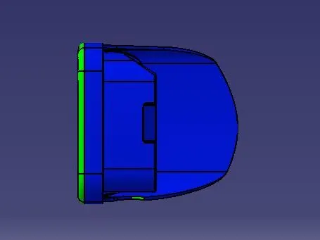
SIDE VIEW
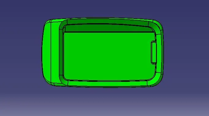
TOP VIEW
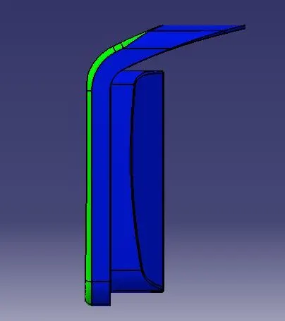
ISOMETRIC VIEW
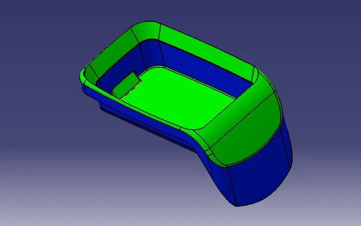
CONCLUSION:
Coin holder plastic component using class-A surface has been successfully created and draft analysis has also been performed for the same.