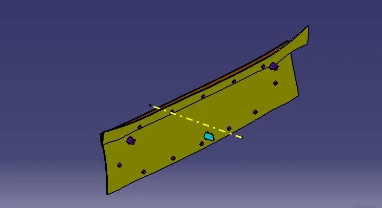
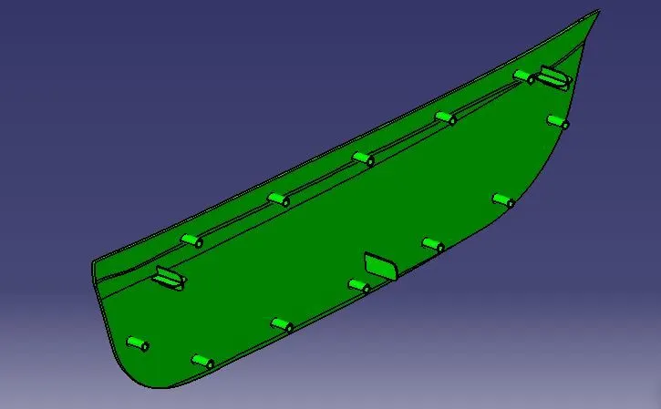
Week 9 - Project 1 - Door Applique Design with Engineering Features
Door Applique Design
AIM: To create plastic design and attach the engineering features and generate the draft analysis.
PROCEDURE:
TOOLING AXIS
- Check for any openings in the given model door applique by using BOUNDARY. In boundary>select edges select the surface to create the boundary at the openings.
- Create a point at the centre of the surface by using point definition by point type on the surface select the surface and distance-0
- By using the line definition option create a line by Line type point Direction, point select the point and Direction extrude 1 which will be the main tooling axis
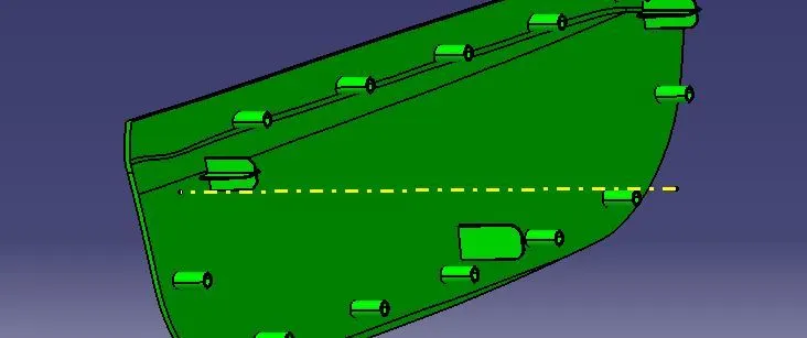
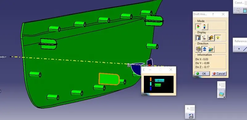
Draft analysis on class A surface
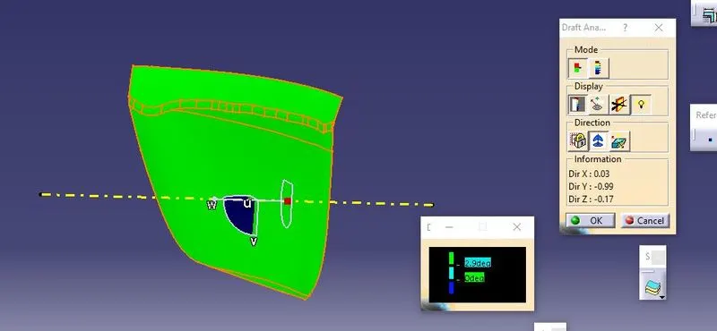
Draft analysis of body
CREATING B-SURFACE FOOR DOOR APPLIQUE
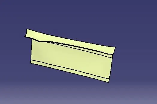
- Extract the class A surface by selecting the surface to extract and untrim the surfaces by selecting the surface which is required.
- Offset the untrimmed surfaces by selecting the surfaces to offset to a distance of 2.5 mm and then trim the surfaces.
- Fillet the surface with a radius and extrapolate the surface.
CREATING C-SURFACE FOR DOOR APPLIQUE
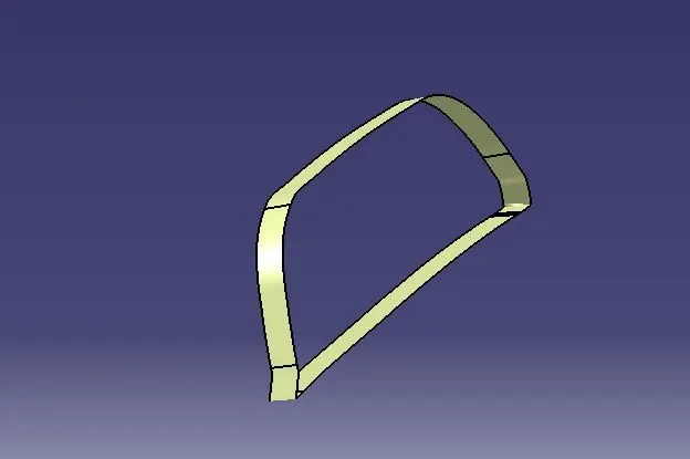
- Extract the boundary of class A by the extract option and using the Sweep option creates the class C surface.
- Smooth curve the extracted boundary and then in sweep option: with draft direction, Guide Curve will be Boundary and Draft direction is Tooling axis, give draft angle 3 degrees.
- After creating the C surface join the class A and Class C surfaces by the join option and then trim it with the B surface.
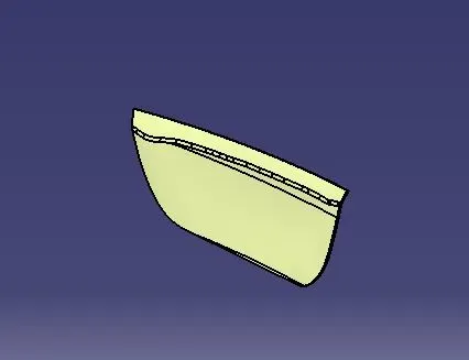
- In part, the design fill the surface body with the solid using a Close surface.
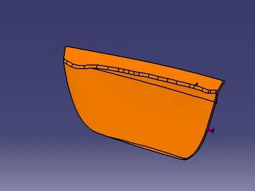
LOCATORS (4 WAY & 2 WAY) TO DOOR APPLIQUE
- Create a point at the centre of the surface of the door attachment by point definition.
- Create a plane on the surface at the centre by plane definition with reference to the point which was created and then create a sketch of a 4-way locator on the plane.
- Pad the sketch in Part Design in pad Type To surface Limit Select the surface as limit and Profile-Sketch and in pad tick mark the THICK option and then click the more option and select the Neutral fibre and the thickness 1.3 should be 40% of the main wall thickness
- Draft the face of the padded area by Faces to draft - select the faces to draft, Neutral element selection-select the base surface and pull the direction-tooling axis.
- After drafting the faces, Chamfer the edges at the top and objects to chamfer-selection the edges.
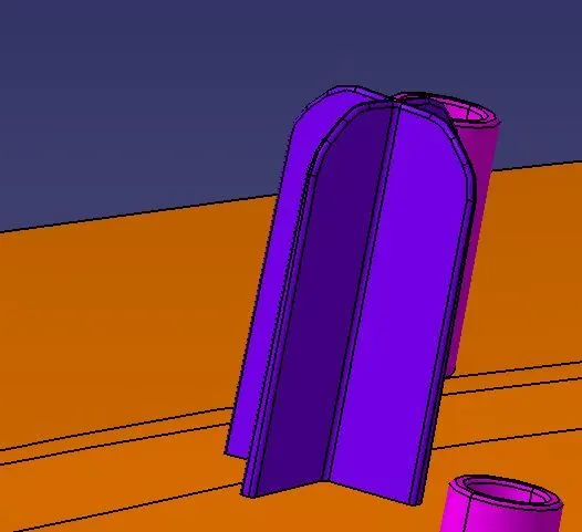
- Copy the part body of the 4-way locator and paste it special with reference link and then Translate it to the other side by coordinates by translate option Vector Definition-Coordinates.
- Now create a 2-way locator below the centre by creating a sketch and do the same process of padding drafting chamfering and filleting By Boolean operation, Unitrim the locator with the solid body of the Door applique by selecting the faces to keep. 2-way locator
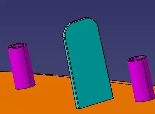
HEAT STAKES
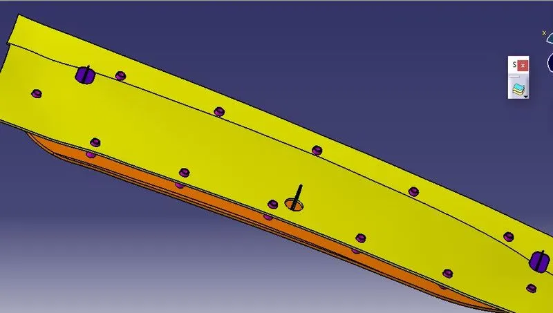
- Offset the Class A surface to 2,5mm and extract the boundaries of the offset surface Parallel curve the extracted boundaries by parallel Curve Definition Curve-Extracted boundary,support-surface, Constant distance.
- Give the points Repetition to parallel curves by points and planes repetition by curve parallel curve parameters-instances and instances-no of points no heat stakes should present nearer to locators.
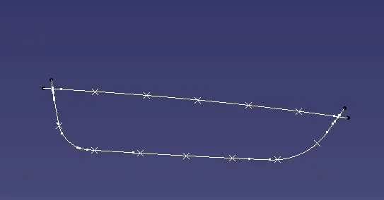
- Now create a sketch of the point created on a parallel curve.
- Draw the circle with diameters of 5mm and 7mm and in part design pad it.
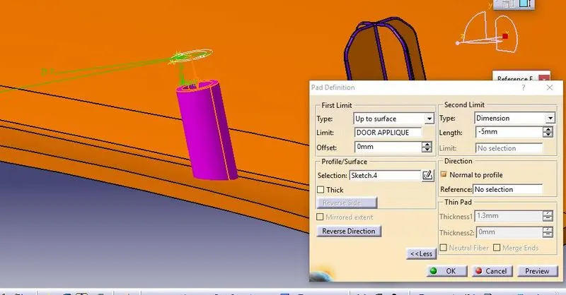
- Copy the part body of the Heat stake and paste it special with reference link and then replicate to the points which are created by the translate. Vector definition-point-point.Translate the part body to heat stake to the other point which was copied by selecting the start point and endpoint.
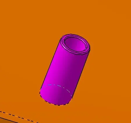
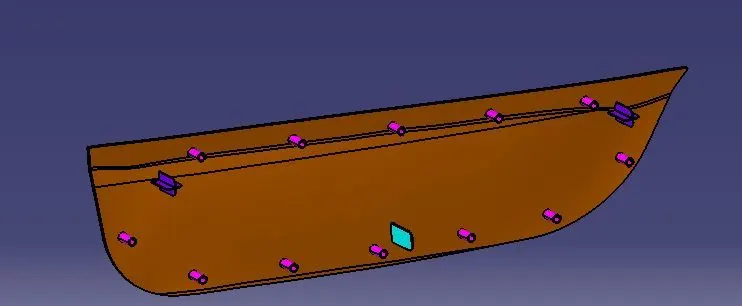
- By Boolean operation. Assemble all the heat stakes part bodies in a single body and then Untrim the Heat stakes with the solid body of the Door Applique by selecting the faces to keep.
- The distance between the top surface of the locator and the door attachment surface should be equal for all locators also the height of the Heat stake should be smaller than the locators.
CREATING CLEARANCES FOR LOCATORS AND HEAT STAKES
- Now from the locator's sketch copy the sketch into a new geometrical set and then draw a circle of 15.2 mm and make the old sketch as construction lines were making the clearance for locators.
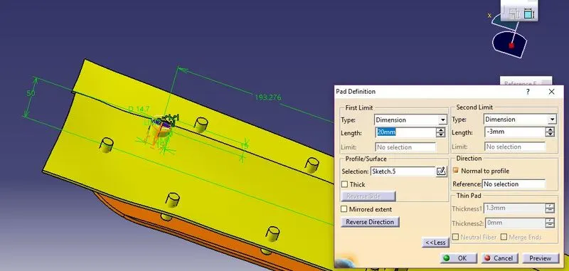
- Pad the circle to an offset distance below the door attachment surface and draft the surface to 0.5 degrees.
- By Boolean operation remove the pad from the Thicken surface.
- So the clearance gap between the locator wall and clearance wall should be 0.1mm to lock the motion.
- Repeat the same process for the remaining locators and heat stakes by creating the Clearance gaps where the Clearance gap for the Heat stake should be 0.5mm Finally do the Draft analysis for the final component.
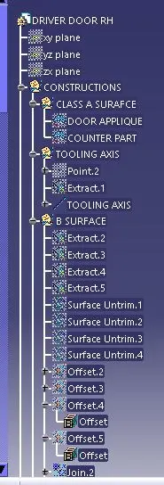
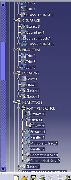
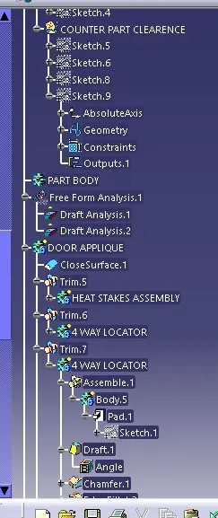
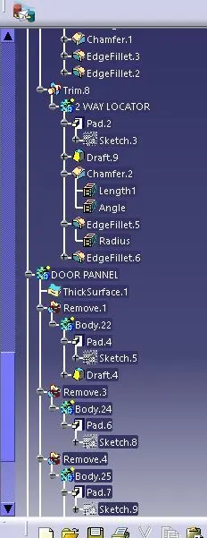
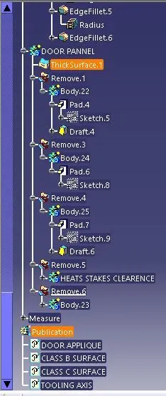
TREE STRUCTURE
FRONT VIEW
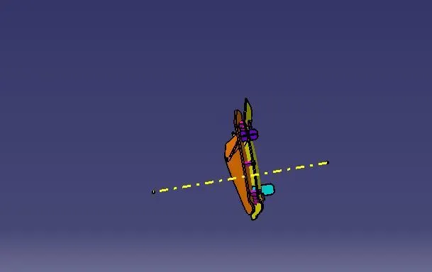
TOP VIEW
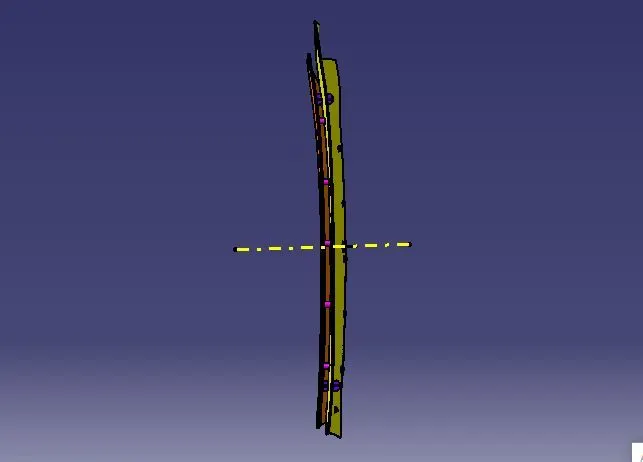
SIDE VIEW
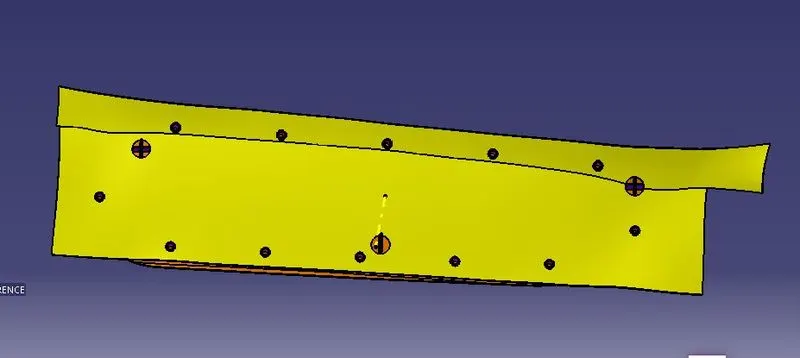
ISOMETRIC VIEW