Radar Mast & Final Assembly of Yacht
RADAR MAST
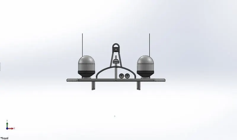
Front View
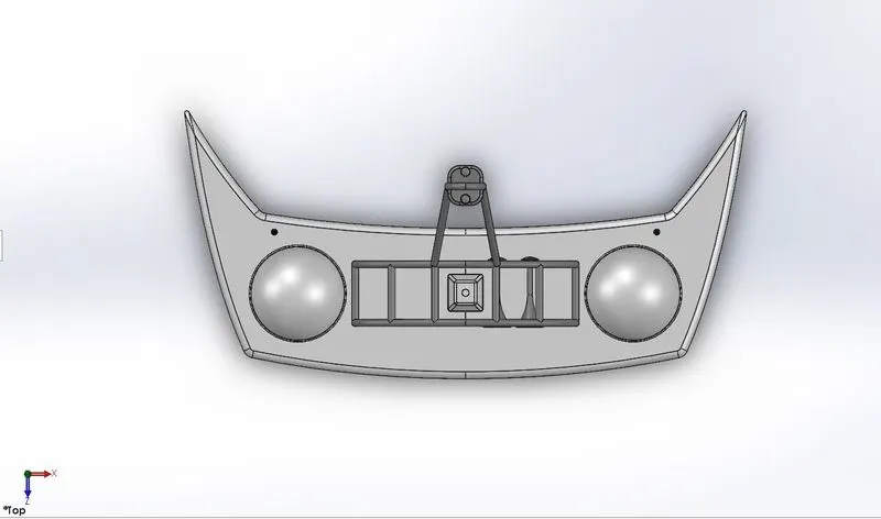
Top view
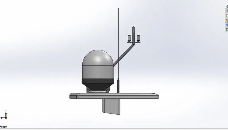
Side view
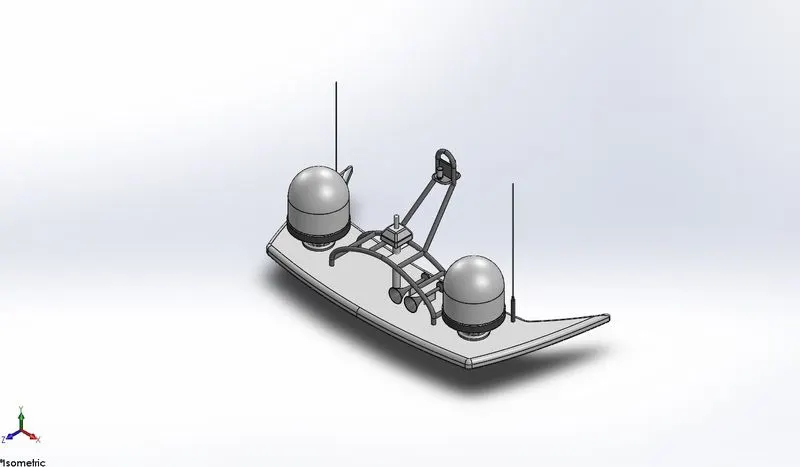
Isometric view
Feature tree
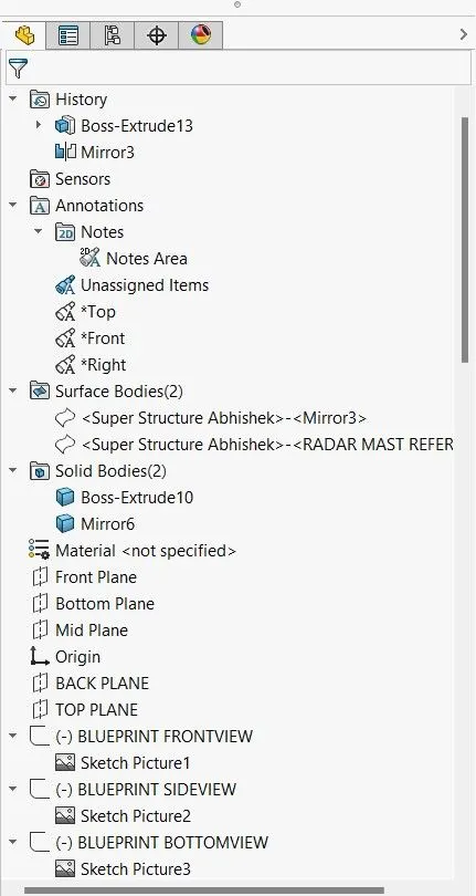
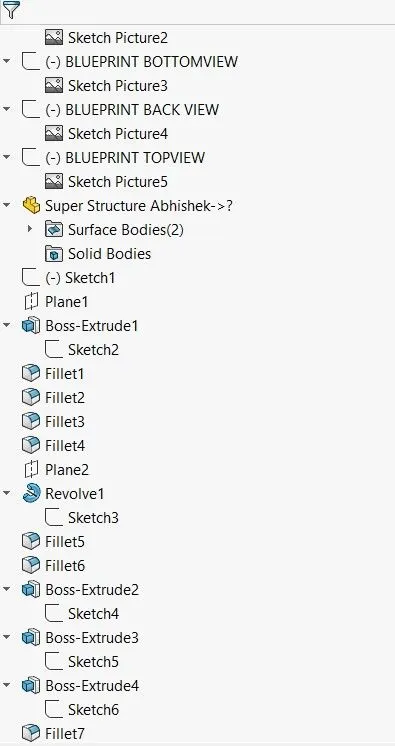
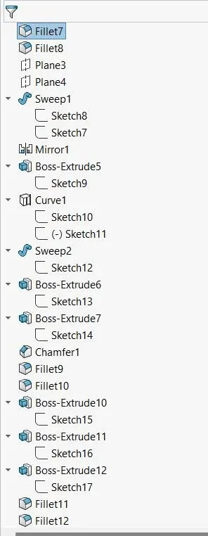
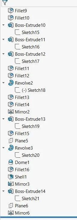
Link of the part: https://drive.google.com/file/d/1FVbSVFeu8fgTuiwMvQLW3g26jsKLFVY_/view?usp=sharing
Assembly of Yacht
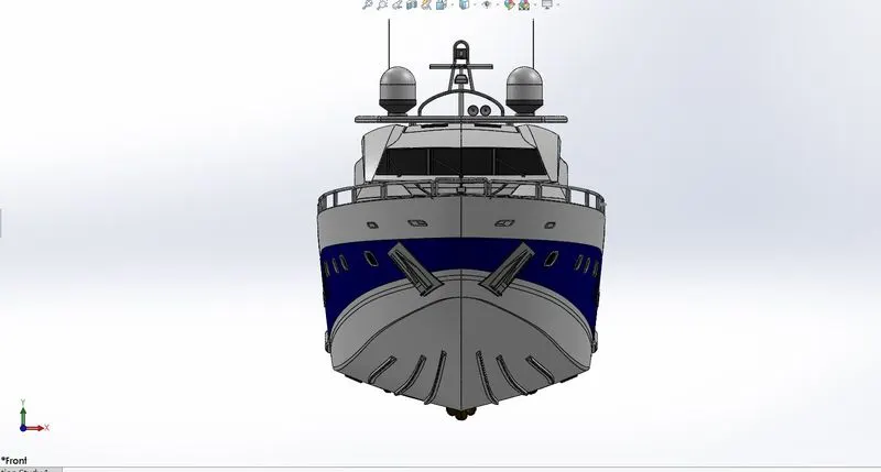
Front View
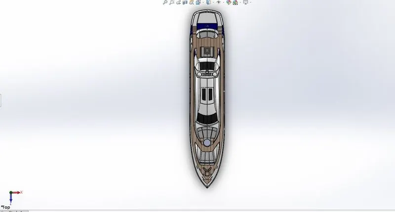
Top View
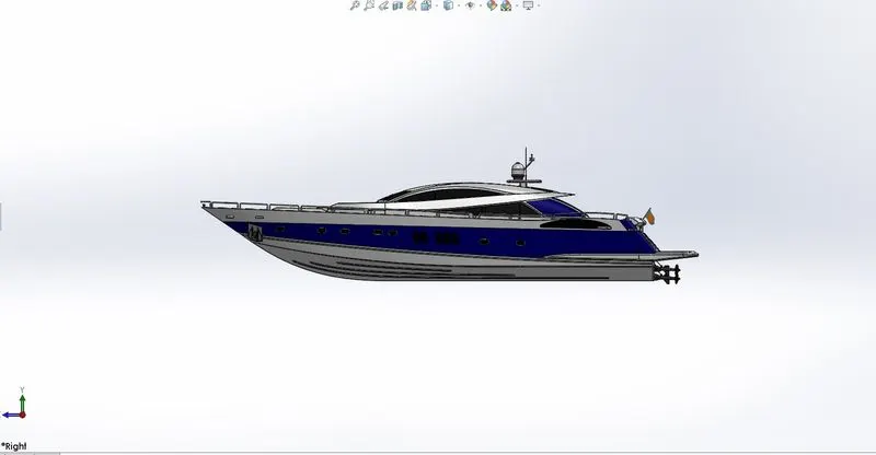
Side View
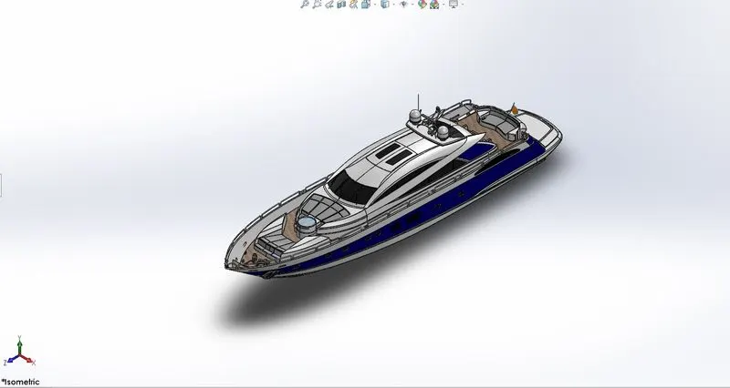
Isometric View
Feature tree
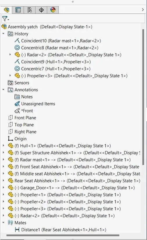
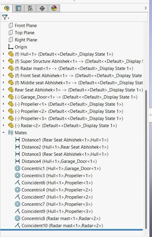
Mates
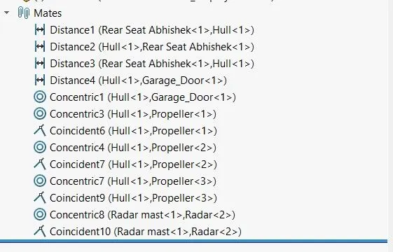
Link of the assembly: https://drive.google.com/file/d/1OBhM1997UZxXc2Ms_j5R-R_jWgHNG4AK/view?usp=sharing
MODELLING AND ASSEMBLING OF SUNSEEKER PREDATOR YACHT
Objective: The main objective is to produce a detailed model of different parts of the yacht with the help of blueprints and some given dimensions, and assemble the entire model.
Design Tool: - Solidworks
Solidworks is a 3D modelling computer-aided design and computer-aided engineering application published by Dassault Systems founded in December 1993.
Solidworks is structured in three basic types:-
- Part mode
- Assembly mode
- Drawing mode
- Part mode is the very first and basic mode of Solidworks in which a 3D model is created. To create any design we have to sketch from the sketching environment. First, we need to select the sketching plane to create a sketch for the base feature. The three default planes are provided namely the Front plane, Top plane and right plane. ( file format:-.SLDPRT)
- In Assembly mode, the assembly is created by assembling the component created earlier in the part mode to form a complete model. We can also create a model by creating parts in assembly mode. Assembly is created by mating relations between parts. These relations are termed Mate tools. ( File format:-.SADLSM)
- Drawing mode is used for the detailing of any created part or assembly. All the detailing or documentation is done in the 2D format in this model. The documentation consists of different drawing views and the details in the drawing views. We can detail all the views by simply dragging and dropping parts or assemblies that we created in part mode or assembly mode. (File format:-.SLDDRW)
Sunseeker Predator Yacht:
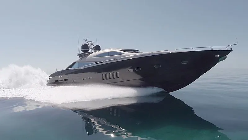
Sunseeker International is a British luxury performance motor yacht brand. Originally named Poole Power Boats, the company was founded by brothers Robert and John Braithwaite in 1969. The company changed its name to Sunseeker International in 1985 and has become a global icon. Its headquarters and main assembly facility are in Poole Harbor, at Poole in Dorset, England. A Predator is poised and dynamic. Offers performance, agility, and exceptional handling, with a low-profile silhouette that cuts through the water. Complete with joystick control and 34-knot capability, she will provide an exhilarating, one-of-a-kind driving experience in a well-appointed surrounding. Over two spacious decks, both modern and classic designs blend harmoniously to exceed even the highest of expectations. On the main deck, expansive windows allow plenty of natural light to illuminate both the dining and separate seating areas. Below deck, three double suites, plus a twin bed guest cabin comfortably accommodate up to eight guests. The cockpit features a blend of contemporary style, design, and modern technologies, while the flybridge is just as sumptuous and innovative. Rarely overshadowed, never outrun. It leaves all others in its wake.
Design methodology:-
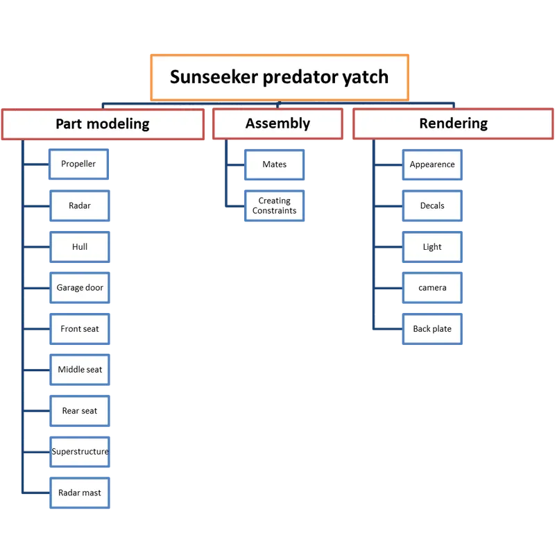
List of Commands with their Explanations:-
Sketch commands:-
- Line: - Used to draw a sketch (midpoint line, construction line …..)
- Arc: - Arcs are created by positioning points.
- Smart Dimension: - we can easily give dimensions to any sketch using this command.
- Ellipse:- Used to draw elliptical shapes in sketch
- Circle: - The circle is another important sketching tool that enables us to create circulars There are two types of circles available Centre circle and the Parameter circle.
- Properties: - This tool enables us to define relations between different sketches in required situations.
- Offset: - It is used to copy a sketch entity to a specified distance from the original entity.
- Slots: - There are 4 types of slots with reference to the centre axis by adding dimension, straight slot and centre point straight slot.
- Rectangle: - Use to draw different types of rectangles.
- Trim: - It is used to delete excess unrequired geometry.
- Extend: - This tool is used to extend the entities to nearby geometry based on the required selection.
- Spline: - Splines are two or three-dimensional curves defined by a set of control points.
- Mirror:- Used to create a reflected copy of the desired entities about a plane/axis/centerline
- Pattern: - This tool is used to pattern the sketch entities either horizontally, vertically or angled or in a circular path. (Linear pattern, Circular pattern).
- Convert Entities: - It is used to copy model edges into an active sketch.
Feature Commands:-
- Extrude: - This tool is used to develop a 3D environment with the reference of the 2D sketch.
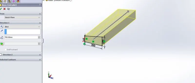
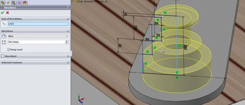
- Revolve: - This feature tool is used to create a solid feature by revolving about an axis. It is mostly used to create cylindrical, pipe or solid bodies which an axis.
- Loft: - It is used to create a solid by connecting two profiles with the reference of the guide curve.
- Extrude cut: - This tool is used to remove a section from a 3d body as per the area defined in the 2D sketch.
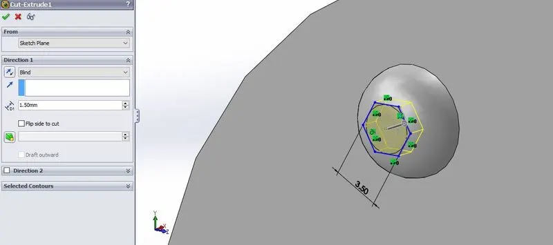
- Pattern: - In the feature tab, this tool also has a similar feature and uses pattern bodies.
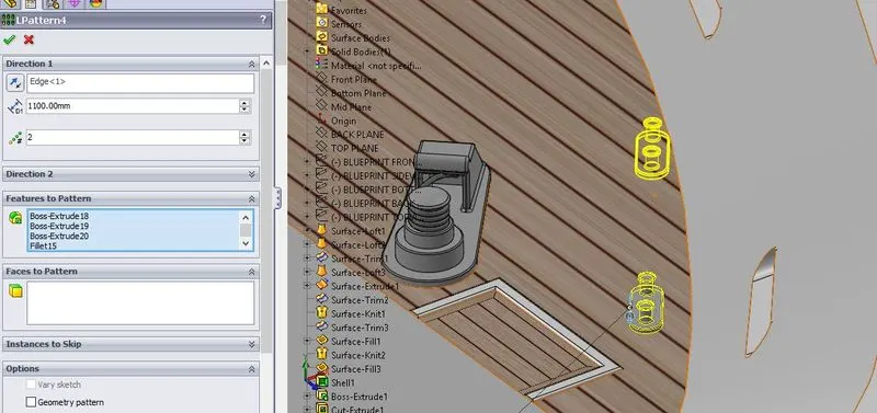
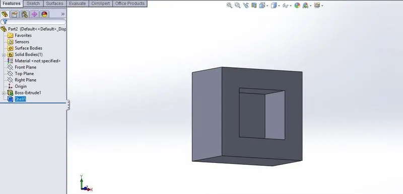
- Shell: - This tool is used to create hollow out apart and can be performed in two ways one by selecting a face that creates a hollow body that leaves the selected face open and creates a thin-walled surface as a boundary to the remaining faces and another by without any selection which creates a hollow solid body with the desired thickness.
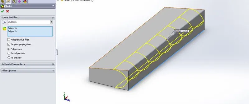
- Fillet: - This tool is used to round the internal or external edge of a part by giving the desired radius.
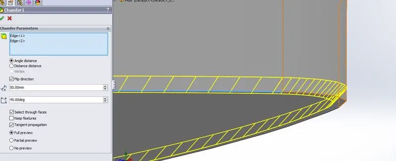
- Chamfer: - Similar to that fillet this tool is also used in the removal of sharp edges but it creates sloping edges. We can define a chamfer with angle – distance or distance-distance method.
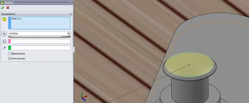
- Dome: - This tool is used by selecting planar or non-planar faces and used to calculate the radius of the arc as a basis for the dome.
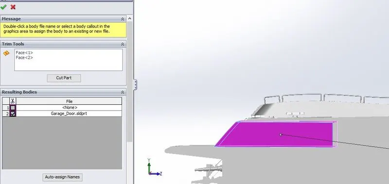
- Split: - This feature is to create multiple parts from the existing part. With the use of this tool, we can split solid bodies as well as surface bodies.
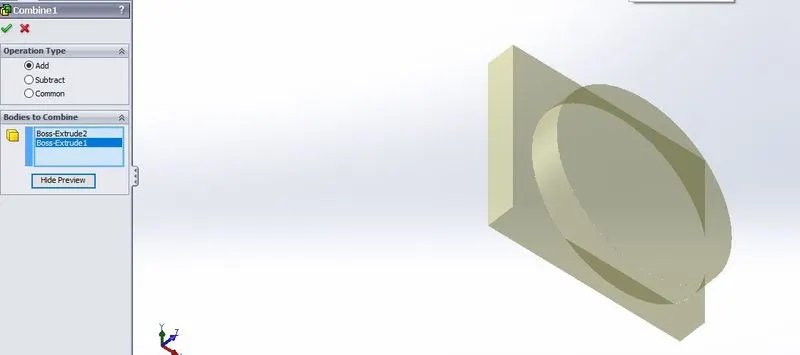
- Combine: - This tool is used to add two or more bodies, get a common area between two bodies or subtract two bodies from each other.
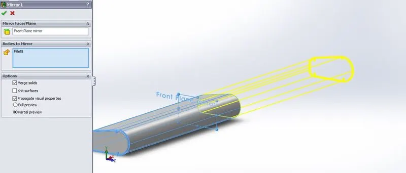
- Mirror: - This tool is used to create a reflected copy of selected bodies along a selected plane/axis.
- Curves: - Projected curves are used to select bi-directional to create a projection that extends at both sides of the sketch.
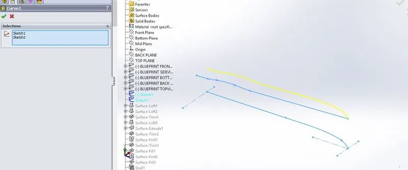
A composite Curve is used to combine curves, sketch geometry, and model edges into a single curve.
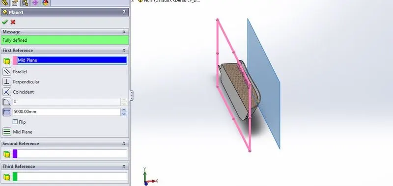
- Reference geometry: - It defines the shape or form of the solid or surface. It includes planes, axis coordinate systems and points.
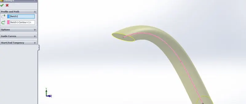
- Swept Boss: - It is used to sweep a sketch along a path. It must be a non-self-intersecting boundary and closed.
- Draft: - It is used to taper faces using a specified angle, selecting faces of the model.
Surface commands:
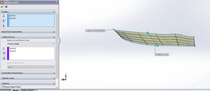
- Lofted Surfaces - Creates a lofted surface between two or more profiles or sketches. Specify start and end constraints and add guide curves to control the path shape.
- Boundary Surfaces- The boundary surface feature lets us create surfaces that can be tangent or curvature continuous in both directions (all sides of the surface). In most cases, this delivers a higher quality result than the loft tool.
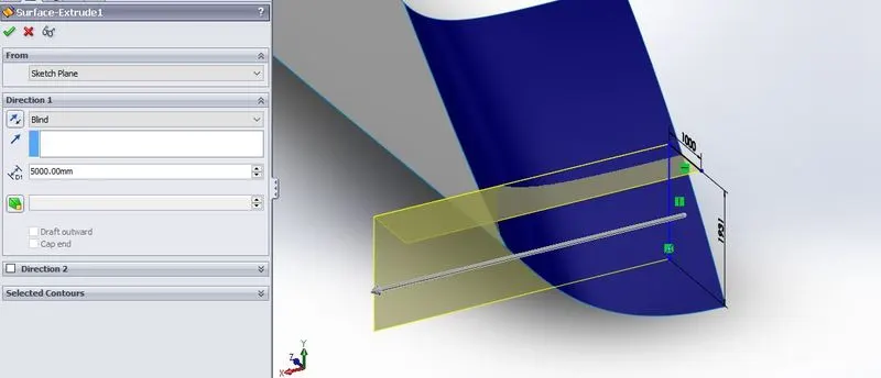
- Extruded Surfaces – Extrudes a sketch or selected sketch contours in one or two directions two create surface features.
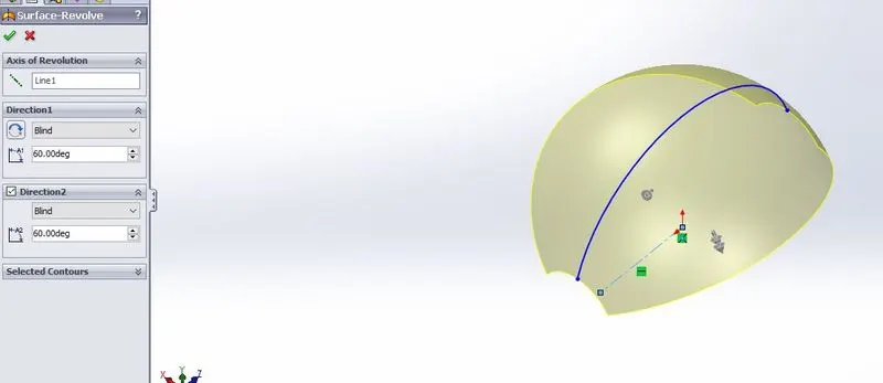
- Revolved Surfaces – Revolves a sketch or selected sketch contours around an axis to create surface features.
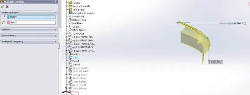
- Swept Surfaces - It Sweeps a closed profile along an open or closed path to create a surface feature. It uses a tangent plane at the end of the path so that the path is normal to the swept surface.
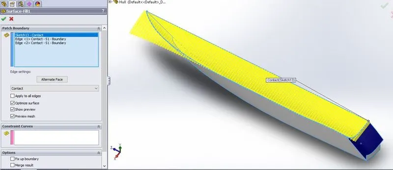
- Filled Surfaces- a surface within a boundary defined by edges, sketches, or curves. We can use constraint curves to fill surfaces and adjust resolution control to improve surface finish.
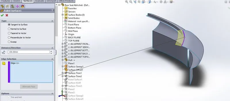
- Ruled Surfaces - Inserts ruled surfaces in a specified direction from the edges. Tangent to the surface, Normal to the surface, tapered to vector, perpendicular to vector or sweep can be selected. We can also trim and knit the surfaces and remove any connecting surfaces.
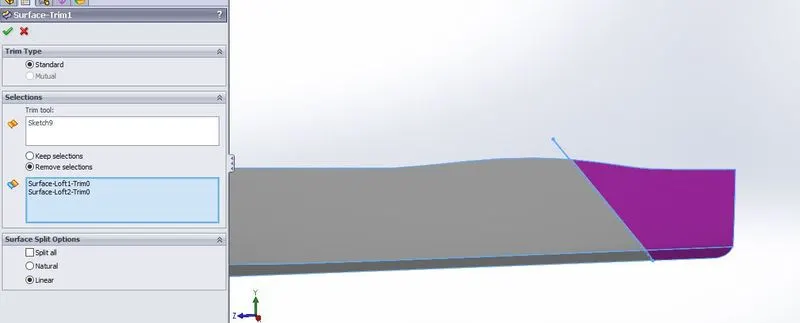
- Trim Surface - It trims the surfaces where a surface intersects with another surface, a plane or a sketch.
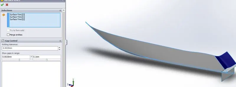
- Knit Surface It combines two or more adjacent, non-intersecting surfaces into a single surface body. The surfaces must joint at an edge. If the resulting knit surface encloses a volume, we can create a solid body from the Property Manager.
- Move/copy surfaces – Moves or copy surfaces about a plane or a sketch
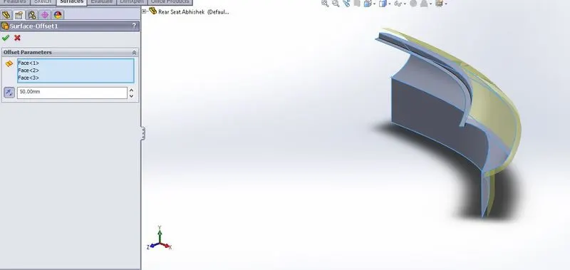
- Offset Surface Offsets surfaces using one or more contiguous faces. This tool helps us to create an offset surface with gaps.
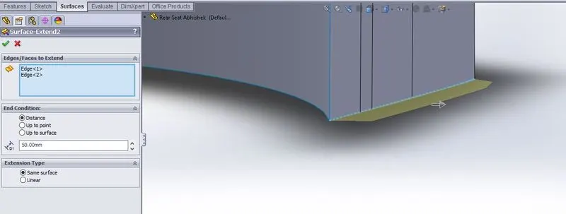
- Extend Surface - Extends one or more edges or faces on a surface, based on end conditions and extension type.
- Mirror surfaces – A mirror feature is a copy of a selected feature, mirrored about a plane or planar face. A minor sketch entity is a copy of a selected sketch entity that is mirrored about a centerline. If the original feature or sketch is modified, the mirrored copy is updated to reflect the change.
- Reference plane We can create planes in part or assembly documents. We can use features, and so on.
- Projected curve A projected curve is typically used either in sweeps and lofts as planes to sketch, to create a section view of a model, for a neutral plane in a draft path or guide curve. There are two types of projected curves
- Sketch on Sketch: Use two sketches to make a single curve.
- Sketch on surface: Use a sketch to project on a surface.
- Split line: The Split Line tool projects an entity (sketch, solid, surface, face, plane, or surface spline) to surfaces, or curved or planar faces. It divides a selected face into multiple separate faces. We can split curves on multiple bodies with one command.
- Split point: We can split a sketch entity to create two sketch entities. Conversely, we can delete a split point to combine two sketch entities into a single sketch entity. Fillet-A fillet is an internal rounding of a corner or edge in a sketch or an edge on a surface.
Bluprint setup:
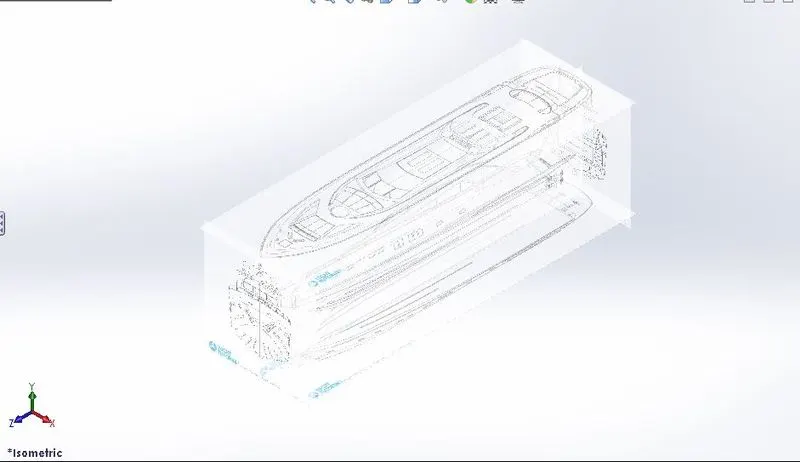
The first step in this project is to set up the blueprints in Solidworks Blueprints are the idea for creating a 3D model or we can say that used as a reference for the entire project development. The blueprints of the yacht consist of different views that are a front view, back view, top view and side. These views are inserted separately set accordingly. To set up blueprints we first import the blueprints into SolidWorks part files using Tools >> Sketch tools >> sketch picture. And arrange these by giving proper dimensions.
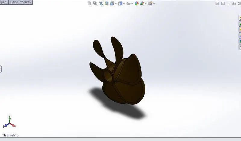
- Propeller: A propeller is a rotating fan-like structure that is used to propel the ship by using the power generated and transmitted by the main engine of the ship. The transmitted power is converted from rotational motion to generate a thrust which imparts momentum to the water, resulting in a force that acts on the ship and pushes it forward.
Sketch command used:
- Circle
- Spline
- Line
- Trim
- Smart dimension
Feature command used:
- Loft
- Revolve
- Reference plane
- Fillet
- Cut extrude
- Circular pattern
- Appearance
Procedure:
- The centre portion of the Propeller was sketched and revolved using Revolved Boss/Base.
- After that the Blades were created by using the Reference Plane, Lofted Boss/Base and Fillet.
- Apply circular pattern for the remaining five blades.
- The centre circular portion was removed using Extruded Cut option.
- Finally, the part was saved by adding the proper appearance.
Link of the part: https://drive.google.com/file/d/14JE_W92sr5m9SBy1-OrIP3dSxO_So40I/view?usp=sharing
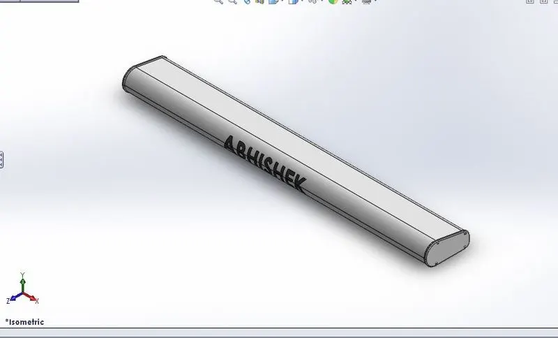
- Radar: It is mounted over the ship used to detect other ships and land obstacles, to provide bearing and distance for collision avoidance and navigation at sea. Actually, they are like electronic navigation instruments that use a rotating antenna to sweep a narrow beam of microwaves around the water surface surrounding the ship to the horizon, detecting targets by microwaves reflected from them, generating a picture of the ship's surroundings on a display screen.
Sketch command used:
- Line
- Smart dimension
- Convert entities
- Offset entities
- Circle
- Point
Feature command used:
- Extrude
- Cut extrude
- Fillet
- Sketch pattern
- Reference plane
- Mirror
- Split line
- Appearance
Procedure:
- By drawing the required sketch, the body of the Radar was created using Extruded Boss/Base.
- Four Dotted holes were created using sketch pattern and then Extruded Boss/Base and Extruded Cut.
- The Radar has a circular slot underneath which was created using the Extruded Cut.
- The other half was mirrored with the help of mirror tool.
- The Text over the Radar was created using the Text option in sketch,
- The Split Line was used to produce over the face of
the radar.
Link of the part: https://drive.google.com/file/d/1U97b2x6wtxwToZJLCIeqZ0_mU8lOQ7T1/view?usp=sharing
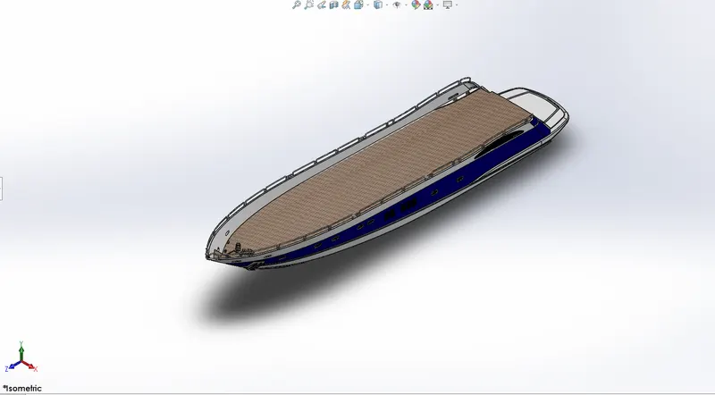
- Hull: A hull is the watertight body of a ship or boat. It is the major part of the yacht we can say that it is the watertight enclosure of the ship, which protects the cargo, machinery, and accommodation spaces of the ship from the weather, flooding, and structural damage. It is the part of the boat which carries all other components of the yacht.
Sketch command used:
- Line
- Smart dimensions
- Circle
- Spline
- Trim entities
- Extend entities
- Offset entities
- Convert entities
- Rectangle
- 3d sketch
Feature command used:
- Extrude
- Cut extrude
- Reference plane
- Mirror
- Projected curve
- Fillet
- Chamfer
- Sweep
- Linear pattern
- Split line
- Revolve
- Dome
- 3d sketch
- Split
Surface command used:
- Surface loft
- Surface trim
- Sweep
- Knit
- Surface fill
- Delete face
Procedure:
- The first step for modeling the Yacht was creating a blueprint of it.
- The Blueprint was placed on the required planes; by using blueprints first, the hull was designed.
- Projected curves are produced by drawing the required sketch using splines with the help of Blueprint.
- the projected curves were lofted to create a lofted surface, and the remaining unwanted surface was trimmed using—the surface trim option.
- The back portion of the hull where the propeller needs to be placed was extruded using Extruded Surface, and all the surfaces Created must be Knitted together to remove the gaps between the surfaces.
- The offset option was used, another surface was created, and each surface was filled using surface fill to create the outer.
- The shell of the hull will be converted into a solid body using the knit surface option.
- The shell feature is used to create a shell in the front portion of the hull.
- The deck surface is created using the Extrude option.
- Then the all the required chamfers and fillets were created .
- All the windows and Portholes were designed using Extruded Cut. Then Fillets were added around the edges.
- create the round edges around the berth window, the reference planes were created, and a circle for the required dimensions Were make pierced and then swept around the edge of the windows to make them round.
- The Rails at the bottom of the Yacht were created using Extruded Boss/Base, and the chamfers were applied on both sides.
- The Cable Rollers were created using Extruded Boss/Base and Swept Boss/Base, and the head part of it was created using.
- Revolved Boss/Base and Extruded Cut was used to cut through the extrude, and a Dome was created over it.
- Helix/Spiral sketch was created to sweep the rope around the Cable Rollers.
- By using the Slot option, the Rope hangers were extruded, the dome was applied, and then the Linear Pattern was used to createOne more.
- The window bars were created using Extruded Boss/Base.
- The staircase was created by using extruded boss/base, and the hand support bar was created using Swept Boss/Base.
- The Railings around the Hull were generated with the help of a blueprint, and the projected curve was produced, and the railing.
- Reference was swept using Swept Boss/Base.
- The Axles, the propeller, and the surfer were created using Revolved Boss/Base option and using the 3d sketch.
- The Anchors are created by sketching the first half and extruding with the use of Extruded Boss/Base, and the other half was Mirrored.
- Finally, the Garage Portion was created by using Extruded Cut, and the portion was saved for later use by using the Split option.
- With the use of the Split line option, the Painting portion for our hull was split separately.
- Then the other half of the Hull and the Axle of the surfer and propeller were mirrored to generate the complete hull using Mirror tool.
- Moreover, the part was saved by adding proper appearances and fillets.
Link of the part: https://drive.google.com/file/d/1R-iVP6ztd7G5CDgHqt3RzCdLE1SKK6Jc/view?usp=sharing
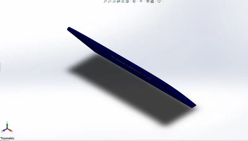
- Garage door: It is a door for the basement of the hull, main purpose of the part is to cover the garage and enhance the look of the yacht. Opening and closing of the door can be done either manually or with the help of an electric motor.
Sketch command used:
- Line
- Smart dimension
- Circle
Feature command used
- Cut extrude
- Shell
- Fillet
- Mirror
- Reference plane
Procedure:
- While manufacturing the Hull, the solid body split was imported to model the Garage Door.
- By using the Extruded Cut, the Chamfered face for the door was produced.
- Then by using the shell feature, the solid body for our garage door was formed, and proper fillets were applied.
- After the door holders on both sides were created using Extruded Cut.
- Half of the Garage Door was placed using the Mirror tool after applying the required fillets.
- Then the text over the garage door was then created using the text option in the sketch feature.
- Lastly, the part was saved by applying proper appearance.
Link of the part: https://drive.google.com/file/d/1tRUoMZeG0MJbyuUHEQ5TOghUQea-kthX/view?usp=sharing
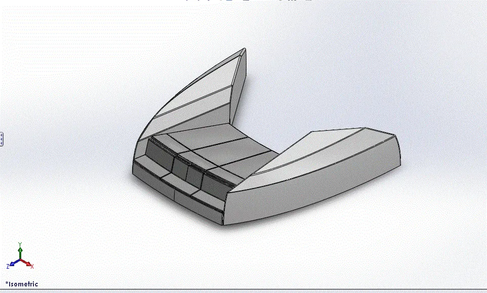
- Front seat: It is mounted over the deck surface of the hull and before the superstructure. It is designed considering the space over the front of the hull and also enhances the look of the yacht. The front seat has sun pads to lean on it.
Sketch command used:
- Line
- Spline
- Circle
- Arc
- Smart dimensions
Feature command used :
- Cut extrude
- Fillet
- Chamfer
- Dome
- Revolve
- Mirror
Surface command used :
- Surface extrude
- Surface trim
- Surface knit
- Surface loft
- Surface fill
- Surface sweep
Procedure:
- The front seat of the Yacht was also created by inserting Blueprint.
- The body of the Front Seat was modeled using Swept Surface, Extruded Surface, Filled Surface, lofted surface.
- The unnecessary part was removed using Trim Surface.
- The four Rest Beds were created using Extruded Boss/Base, and the dome was created over the face of the beds separately.
- Required fillets and chamfers were created with the extruded thin surfaces.
- Lastly, the part was saved by adding proper appearances.
Link of the part: https://drive.google.com/file/d/1oP2gYwR01Se8N5wEM8VqctzIRWXpC2Ml/view?usp=sharing
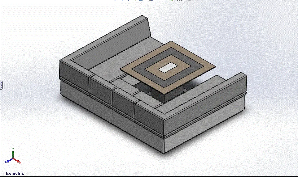
- Middle seat: Middle seat in the yacht is mounted over the deck of the hull behind the superstructure. The middle seat of the yacht consists of a table surrounded by a three-sided seat.
Sketch command used:
- Line
- Smart dimensions
- Trim entities
- Covert entities
- Offset entities
Feature command used:
- Boss extrude
- Chamfer
- Fillet
- Mirror
- Reference plane
- Appearance
- Cut extrude
Procedure:
- The Middle Seat was created using the Extruded Boss/Base and by applying the Chamfers and fillets as wanted.
- All the surfaces created must be Knitted together by using the option Knit Surface.
- The Table was created using Reference Plane, Extruded Boss/base, Off-set, Chamfers, and Mirror.
- The other half of the Middle Seat must be mirrored symmetrically.
- At last, the part was saved by applying the proper appearances.
Link of the part: https://drive.google.com/file/d/1803vVYATwmWK0rk-M07LRZ_7aLJrAjKS/view?usp=sharing
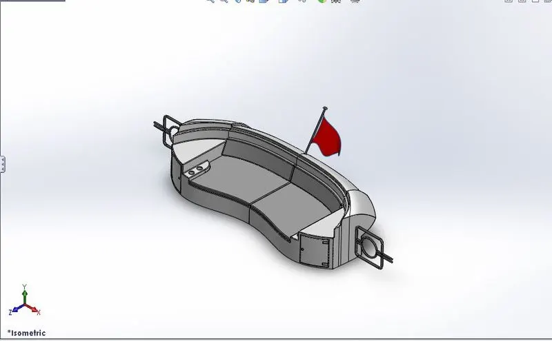
- Rear seat: Like all other seats it is also mounted over the deck of the hull close to stairs. The rear seat includes rear light, gate, cup holder, drawers and flag pole.
Sketch command used:
- Line
- Spline
- Circle
- Smart dimensions
- Trim entities
- Offset entities
- Convert entities
- Rectangle
Feature command used:
- Boss extrude
- Cut extrude
- Chamfer
- Fillet
- Mirror
- Sweep
- Revolve
- Reference plane
Surface command used:
- Surface sweep
- Surface offset
- Surface trim
- Ruled surface
- Knit surface
- Surface extend
- Surface loft
Procedure:
- The chief body of the Rear Seat was modeled with the help of Swept Surface, Off-set Surface, and the remaining portion was trimmed using the Trim Surface tool.
- By using the Reference Plane, the Seats were created with the help of surface trim, lofted surface, and Extended Surface.
- The Flag Post was created with the help of Revolved Boss/Base, and the Flag was created by drawing the required 3D sketch, and then the 3D sketches were lofted to form the Flag.
- The Tail Lamps were created using Extruded Boss/Base, mirror tool, and fillets.
- The Steel Gates for Stairs were designed by using the reference plane and the Swept Surface.
- All the Surfaces must be Knitted together with the help of Knit Surface.
- The required fillets and chamfer were created before mirroring the second half using the Mirror tool
- After mirroring; the uncreated areas were filleted once more. Finally, the part was saved by adding suitable appearances.
Link of the part: https://drive.google.com/file/d/1znFsxxnw-eE1s9-Hllg1YBKbJG_1sn_a/view?usp=sharing
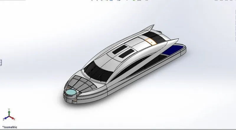
- Superstructure: A superstructure is an extended construction of any building or platform that rises above the rest of the building or platform distinctly. The size of the superstructure has a great influence on the mobility of the vessels. They are designed in a manner, so that, they add value and hinder speed and mobility in the least. It is designed to enhance the look of the yacht because it is the most easily visible part of the ship it is the identification of the ship, and so the designers try to provide it with a unique identity. It is mounted over the hull with a Jacuzzi amenity.
Sketch command used:
- Line
- Spline
- Circle
- Smart dimensions
- Trim entities
- Offset entities
- Convert entities
- Rectangle
- Arc
- 3D sketch
Feature command used:
- Extrude
- Cut extrude
- Reference plane
- Mirror
- Projected curve
- Fillet
- Chamfer
- Sweep
- Linear pattern
- Split line
- Revolve
- Dome
- 3d sketch
- Split
Surface command used:
- Surface sweep
- Surface offset
- Surface trim
- Ruled surface
- Knit surface
- Surface extend
- Surface loft
- Mirror
- Thicken
- Delete face
Procedure:
- The deck surface from the hull was imported, and the Superstructure was modeled over it.
- The side surface of the Superstructure is created using Extruded Surface, Lofted Surface, Filled Surface, Trim Surface, and Knit Surface.
- The Front Side of the Superstructure was designed to have four rest beds which were created using Extruded Boss/Base, Fillets, and Dome.
- The front edge of the Superstructure was provided with a Water Feature, which was formed using Extruded Boss/Base, Extruded Cut, and filled with water appearance.
- The Windshield was created by Extruded Cut, the wipers were created by using a 3D sketch, and the reference plane was created using Swept Boss/Base.
- The Portholes for the Superstructure are formed by using Extruded Surface, Trim Surface, and Extend Surface.
- The left-out edges were filled using the ruled Surface.
- The Back Doors of the Superstructure were formed using Extruded Cut, Fillets, and Reference Plane.
- All the surfaces were Knitted together to form a solid body.
- The Superstructure consists of two surface bodies and five solid bodies. One of the surfaces was the Deck Surface. The other one was used to place the Radar Mast, so it was renamed as Radar Mast reference Surface.
Then the other half was mirrored, and the proper fillets and appearance were added
link of part: https://drive.google.com/file/d/1jOC9jUxKjz_RxQctzpf9jgMC4C5plZjz/view?usp=sharing
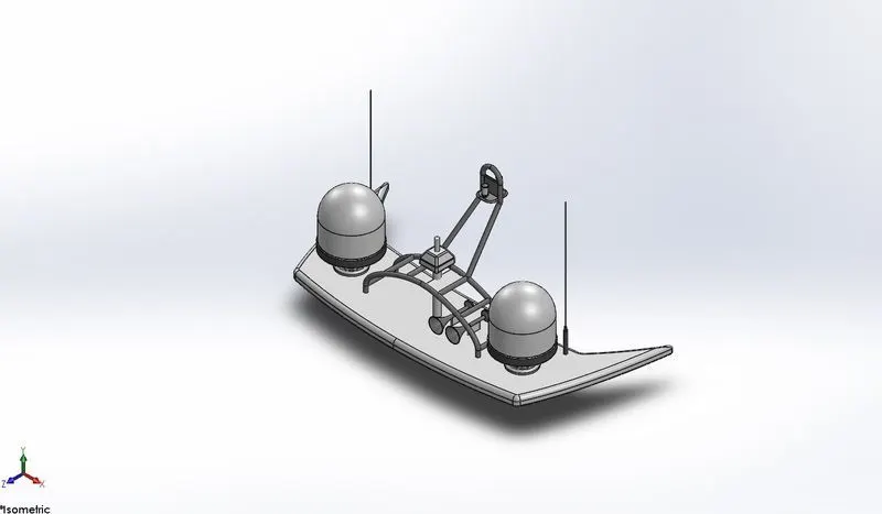
- Radar mast: A radar mast is that part of the yacht which is mounted over the superstructure and carries important electronics devices connected to radar, like antenna, horns and lights. Radar is mounted over the radar mast.
Sketch command used:
- Line
- Spline
- Circle
- Smart dimensions
- Trim entities
- Offset entities
- Convert entities
- Rectangle
Feature command used:
- Extrude
- Fillet
- Revolve
- Sweep
- Reference plane
- Mirror
- Chamfer
- Dome
- Shell
Procedure:
- The first half of the Radar was Modelled with the help of a blueprint
- The second half was mirrored with the help of the Mirror tool.
- The body of the Radar was created with Extruded Boss/Base and Revolved Boss/Base.
- The antenna of the Radar was also created using the Extruded Boss/Base.
- The lampstand, along with the connecting rod, were designed using the Swept Boss/Base and Mirror tool.
- The lamp was created using the projected curve, and then the curve was swept using swept boss/base.
- The horns were designed using the Revolved Boss/Base, Dome, and Shell.
- After the fillets and chamfers were applied wherever necessary.
- In the end, the part was saved by applying appropriate appearances.
Link of the part: https://drive.google.com/file/d/1FVbSVFeu8fgTuiwMvQLW3g26jsKLFVY_/view?usp=sharing
Assembly of sun seeker predator yatch
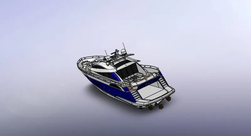
The designed model is inserted into the assembly profile using an insert part option in Solidworks. The mate features are used to assign the relation between the parts modelled which are parallel, coincide, concentric, perpendicular, fix, etc. relations which assign the parts to their proper position and make a complete assembled Sunseeker predator yacht. Once the assembly of the yacht is completed, the decals are provided to the respective parts using photoview360.
Commands used during Assembly:
- Insert components
- Mates
Front View
Top View
Side View
Isometric view
camera setup 1
Camera setup 2
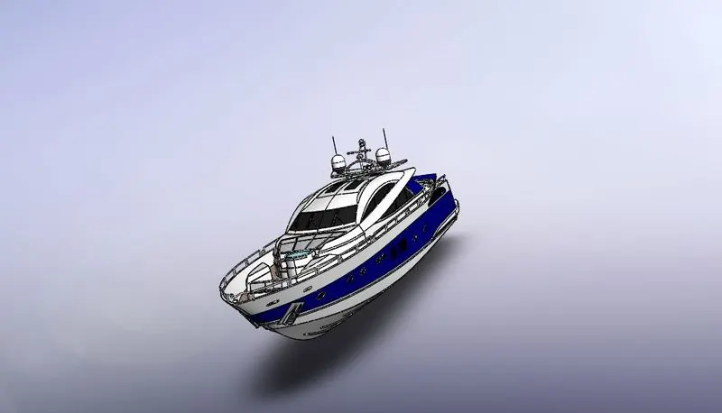
Rendering: - Rendering is the process of generating a photorealistic or non-photorealistic image from a 2D or 3D model by means of a computer program. The term "rendering" is also used to describe the process of calculating effects in a video editing program to produce the final video output.
some of the rendered images of the yacht are:
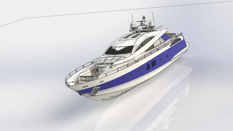
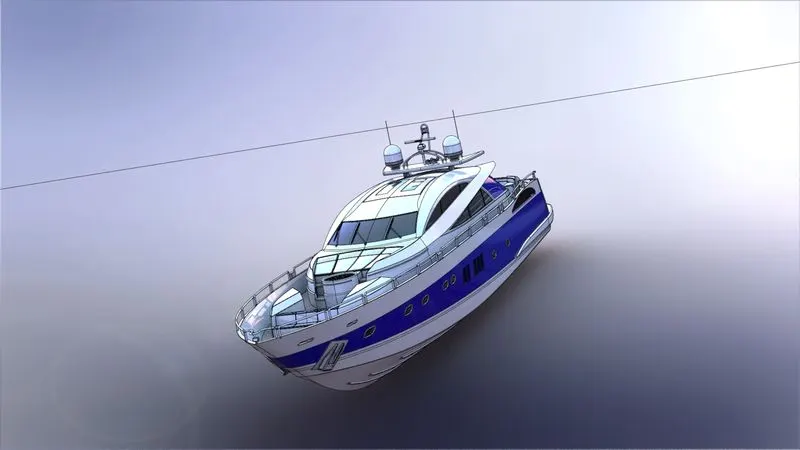
Visualization:- SOLIDWORKS Visualize allows us to leverage our 3D CAD data to create photo-quality content in the fastest and easiest way that we can from images to animations, interactive web content, and immersive Virtual Reality can bring our products to life. SOLIDWORKS Visualize is the “camera” for our CAD data.
Here is some final output from Solidwork visualize:
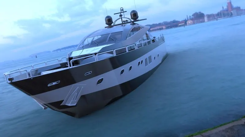
Fig. abhishek_render_1
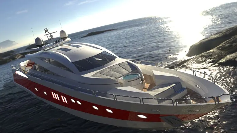
Fig. abhishek_render_2
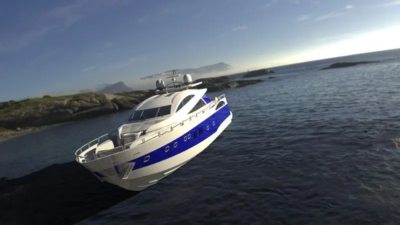
Fig. abhishek_render_3
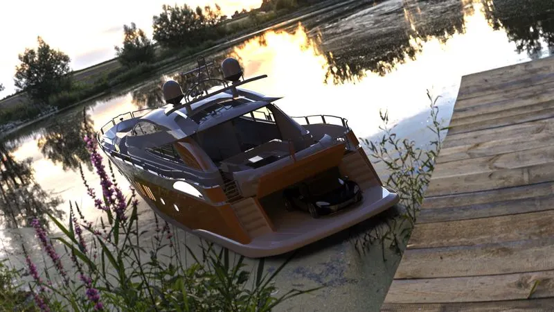
Fig. abhishek_render_4
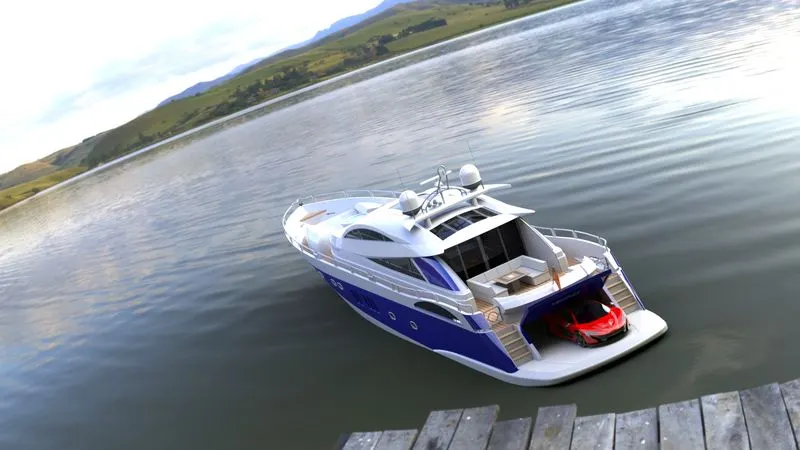
fig. Abhishek_render_5
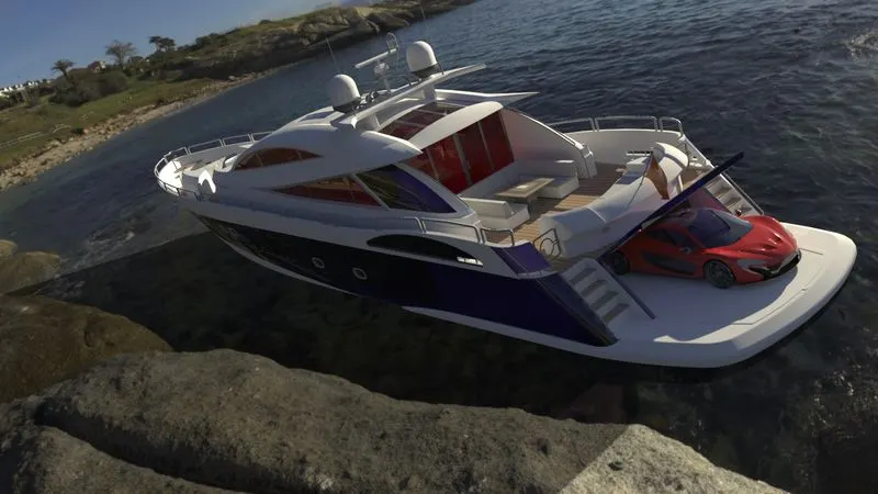
Fig. abhishek_render_6
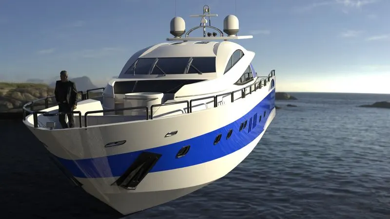
Fig. Abhishek_render_7
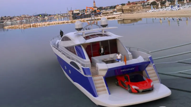
Fig. Abhishek_render_8
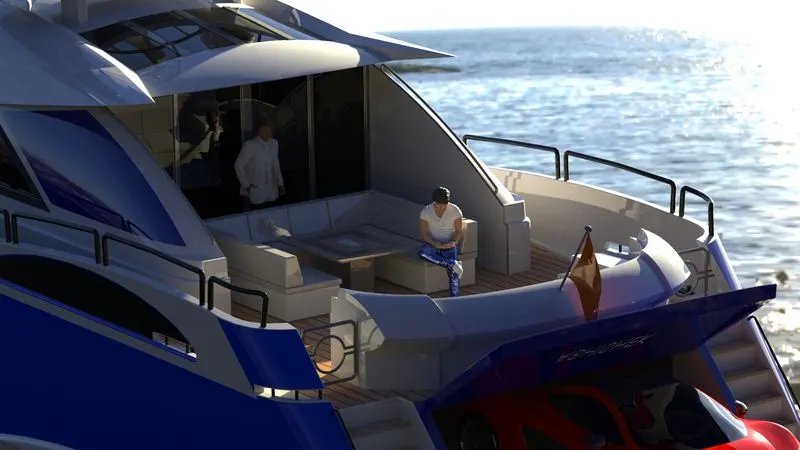
FIg. Abhishek_render_9
Conclusion: The Sunseeker predator is assigned to understand the tools and 2D features of the solidworks with the proper functioning. All the parts were designed, assembled, rendered and visualized properly.The modelling of Sunseeker predator yatch is completed successfully.