Wiring harness design in CATIA V5 - 3D modeling Week 5 & 6 Challenge
Wiring harness design
Aim:
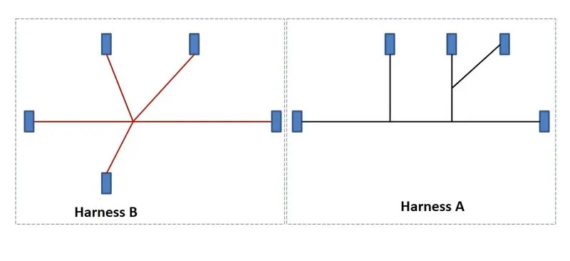
Route two electrical harnesses as per the given layout and interconnect them as a single harness assembly and then check for bundle continuity, and bundle warnings, and then provide annotations for the final harness assembly.
Objective:
- The numbers in the above figure represent the electrical connectors. There are 8 different types of connectors at 10 different locations.
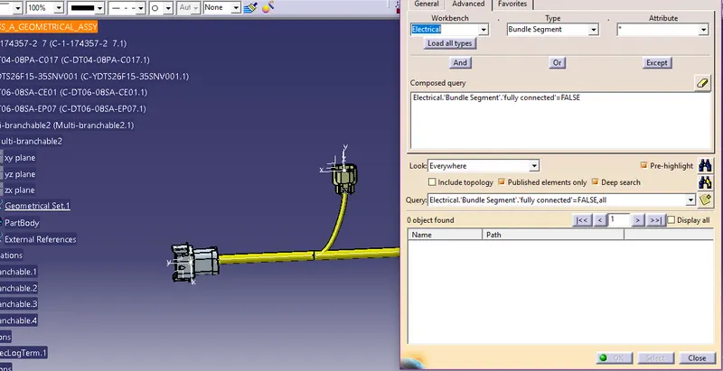
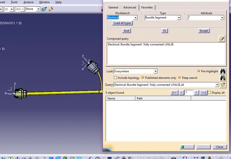
Bundle continuity has to be checked for the two created harnesses. - After the two Harnesses are created, the next objective is to connect them electrically. Check for bundle warnings in Harness A and Harness B.
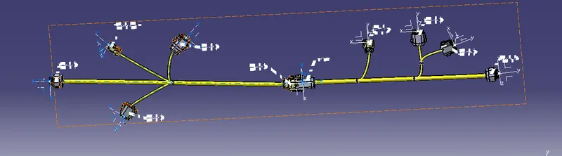
- Add annotations to all the connectors in Harness A and Harness B.
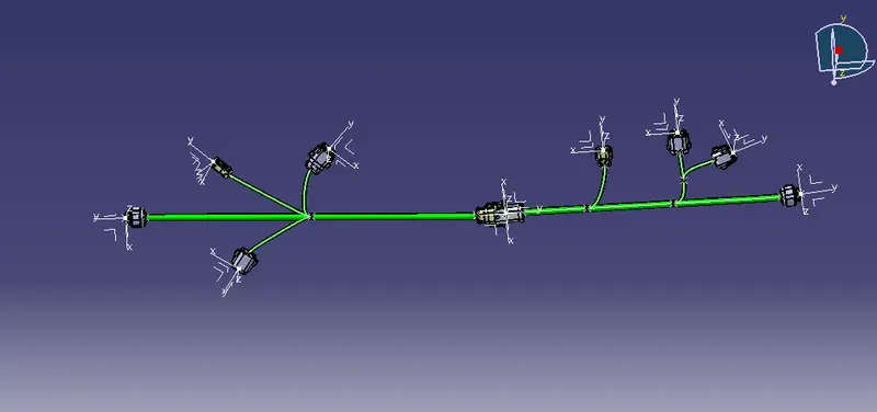
- The final objective of this project is to convert the final harness file into an IGS file format.
Procedures:
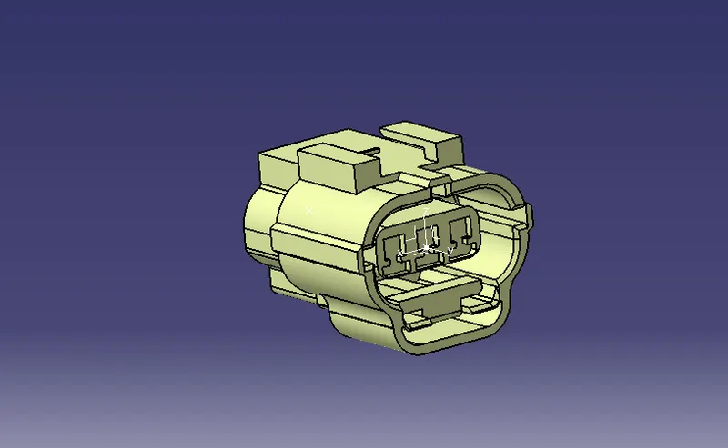
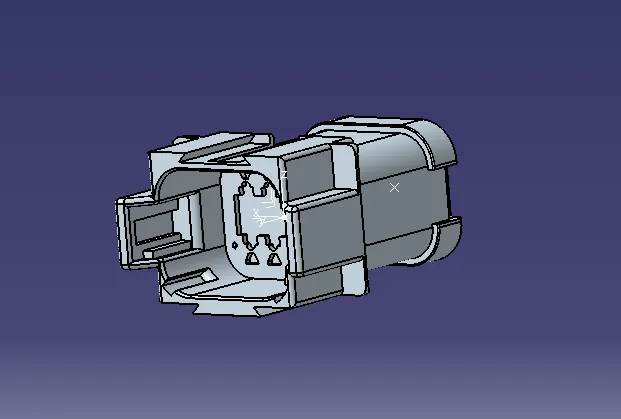
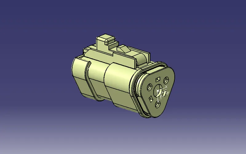
- Define all the electrical connectors geometrically and electrically so that they can be used in the wiring harness.
- First, create Geometrical parameters such as points and Axis to the Electrical connectors.
- Then define all the components as Connectors and define connector connection point and bundle connection point for each connector.
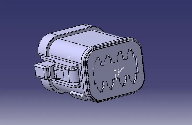
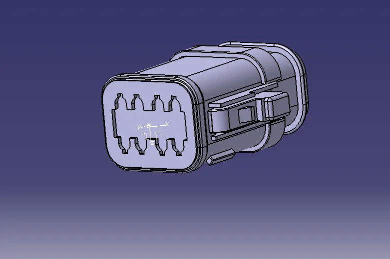
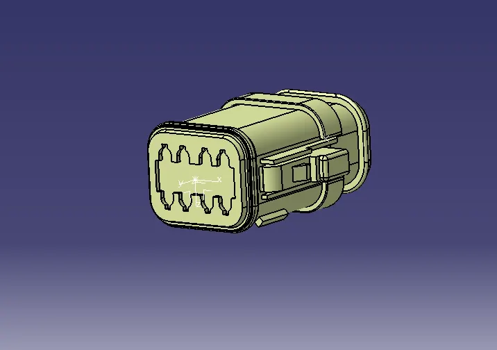
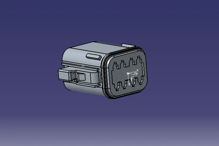
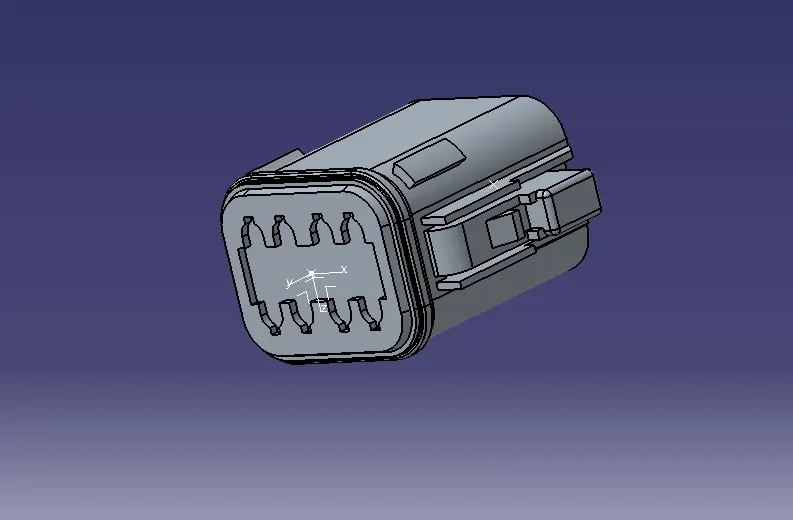
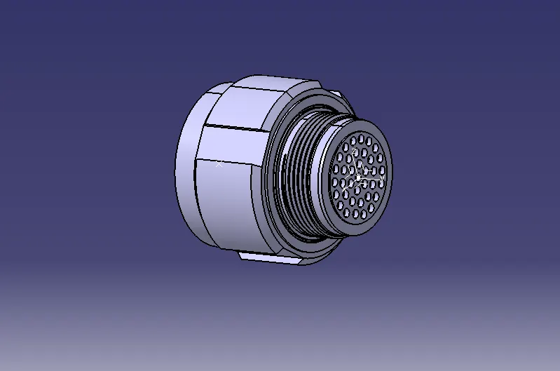
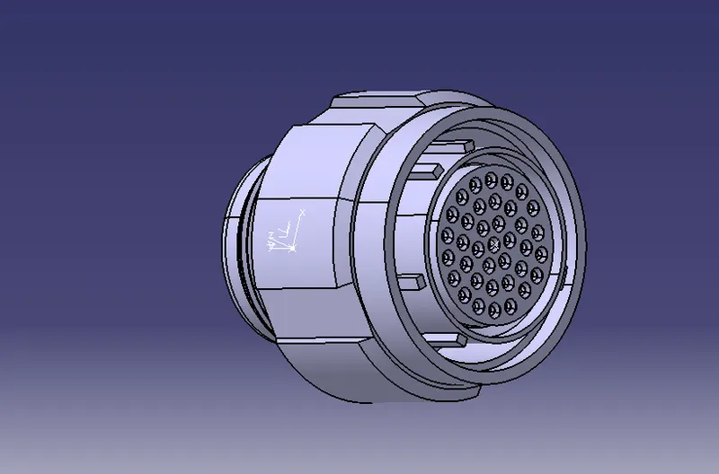
Create Harness A and B:
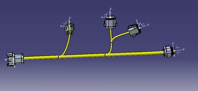
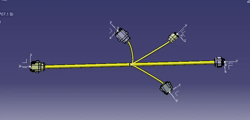
Harness A and harness B were created as shown below by using the electrical harness workbench in CATIA V5.
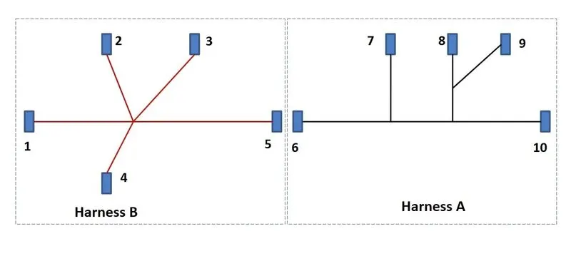
- First, all the connectors are placed at their desired locations. Second, bundle segments are created between the connectors with branch points and branches.
- Bundle diameter is assumed to be 10mm, and 5mm for different bundle segments. The bend ratio is given as 1.4 and slack is given as 0% for all the bundle segments.
HARNESS A
HARNESS B
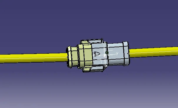
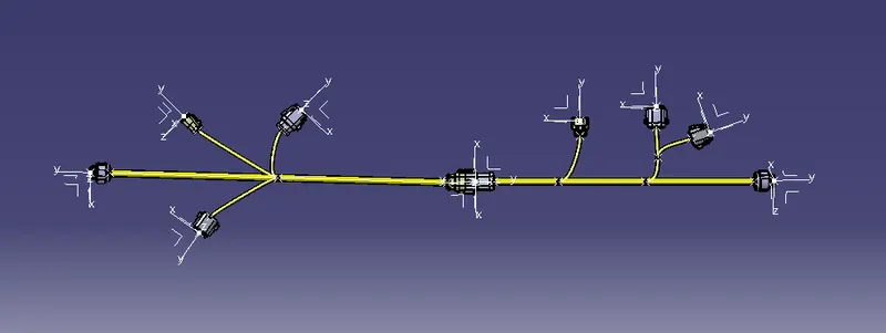
ASSEMBLE HARNESS A & B:
In this step, we have to interconnect the Wiring Harness A and Harness B electrically. There are a few steps that have to be followed to connect the two harnesses electrically.
BUNDLE CONTINUITY
HARNESS A
HARNESS B
3D ANNOTATION
In this last step, we have to convert our Final Harness Assembly file into a PART file and IGS format.
CAT PART
CONCLUSION:
Here, The electrical connectors were defined with necessary properties and Created two harness assembles from the given layout and connected with a connector. then checked bundle continuity, bundle warnings and annotations, finally changed to part file and .igs file format.