Project 2 Adaptive Cruise Control
General Overview:
Adaptive Cruise Control Feature for passenger cars allows the host vehicle to adapt to the speed in line with the flow of traffic. Driving in heavy traffic or keeping a safe distance to the preceding vehicle calls for a high level of concentration. The Adaptive Cruise Control feature can reduce the stress on the driver by automatically controlling the vehicle speed & maintaining a predefined minimum distance to the preceding vehicle. As a consequence, the driver enjoys more comfort & can concentrate on the road a little better.
A radar sensor is usually at the core of the Adaptive Cruise Control. Installed at the front of the vehicle, the system permanently monitors the road ahead. As long as the road ahead is clear, the cruise control feature maintains the speed set by the driver. If the system spots a slower vehicle within its detection range, it gently reduces speed by releasing the accelerator or actively engaging the brake control system. If the vehicle ahead speeds up or changes lanes, the cruise control automatically accelerates to the driver’s desired speed.
Standard Adaptive Cruise Control can be activated from speeds of around 30 km/h (20 mph) upwards and supports the driver, primarily on cross-country journeys or on freeways. The cruise control stops & go variant is also active at speeds below 30 km/h (20 mph). It can maintain the set distance to the preceding vehicle even at very low speeds and can decelerate to a complete standstill. When the vehicle remains stopped longer, the driver needs only to reactivate the system, for example by briefly stepping on the gas pedal to return to cruise control mode. In this way, cruise control stops & go supports the driver even in heavy traffic and traffic jams.
Since Adaptive Cruise Control is a comfort and convenience system, brake interventions and vehicle acceleration only occur within defined limits. Even with Adaptive Cruise Control switched on, it remains the driver’s responsibility to monitor the speed and distance from the vehicle in front.
Objective of the Project:
- Developing Adaptive Cruise Control feature as per the Requirement Document using MATLAB Simulink.
- Follow all the MBD-related processes: Requirement Tagging & Traceability, SLDD creation, Configuration Parameter changes, Model Advisor check & Code Generation.
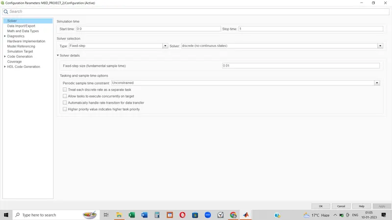
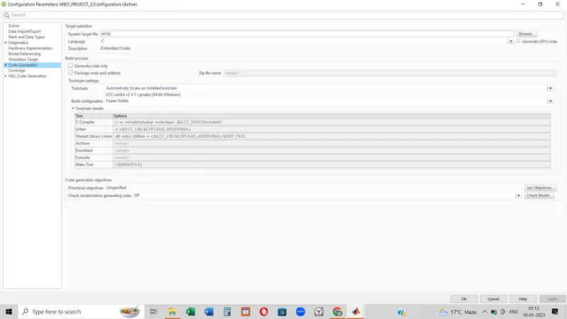
- In Configuration Parameters: enable “Support Floating Numbers” under Code Generation settings.
- Use Embedded Coder to generate the code.
- If choosing code generation, Storage class for Input signals: ImportedExtern; Storage class for Output signal: Export to File; Storage class for local signals: localizable; Storage class for calibration signals: Const.
- Choose sample time for all signals as 0.01s.
What is Cruise Control:
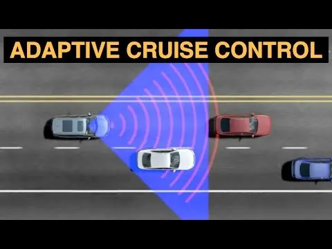
Basically, cruise control is a feature that maintains the speed of a car at a speed set by the driver without him needing to use the accelerator or brake pedals. This feature maintains the speed of the vehicle without any intervention by the driver. Through this feature, the car continues moving at the set speed without letting it increase or reduce the speed. This feature is now available even in the top versions of some of the affordable cars in India.
Essentially, cruise control is a feature that replicates the driver’s action of acceleration and braking to maintain the vehicle at the set speed. However, it does this without actually using the accelerator or brake pedals to maintain a constant speed. At first, this system made use of cables to control acceleration without manual intervention. The speed was adjusted by engaging the throttle through an actuator controlled by a cable. Depending on the speed set by the driver, the actuator adjusted the throttle position for required power and speed generation.
However, thanks to modern technology, cruise control systems are now fully electronic. Instead of any cable, the system governs the throttle through various sensors that are connected to the Electronic Control Unit (ECU). Hence, as soon s the driver sets a speed, the ECU calculates the throttle position that’s required to maintain the speed and controls the throttle wirelessly. This speed is maintained irrespective of the road conditions through adjustment of the throttle.
Steps followed:
- SLDD creation:
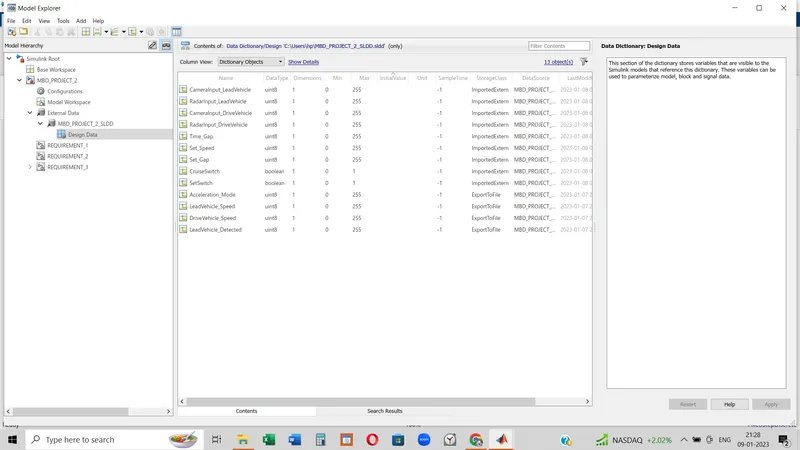
Data are already referred to in the question. As per the data we need to create a data dictionary that will be liable for generating all the variable input-output values as per the model requirement and operation. To create a data dictionary following steps should be followed:
Modeling tab --> Model Settings --> Model Properties --> (pop up window) --> External data --> New --> choose the name and put all the data which will be conducted during operation.
- Requirement_1
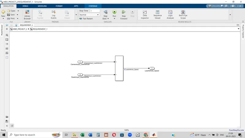
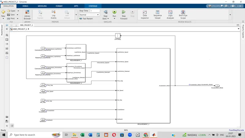
Here by using ADD block two signals are added and the output name 'Lead Vehicle Speed' comes out. This output later will feed to Requirement_3 as an input signal. Two input signals of the Requirement_1 are Camera_Input_lead_Vehicle and Radar_Input_Lead_ Vehicle.
- Requirement_2
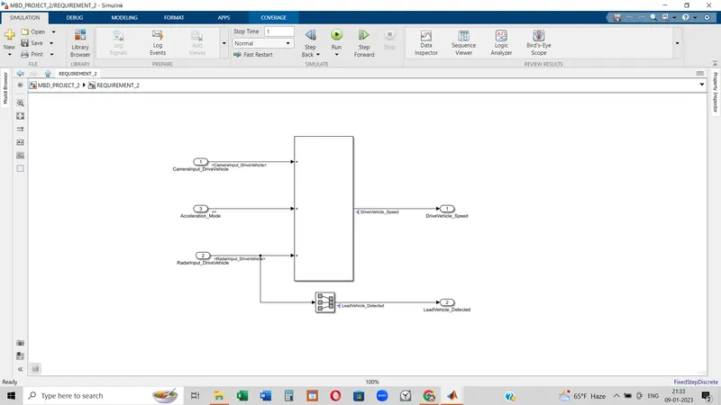
By using ADD block 3 signals as input have been added here and these are Camera_Input_drive_vehicle, Radar_Input_drive_vehicle, and Acceleration_mode. The Acceleration_mode has come from the output of the whole model itself by implementing a feedback signal. But To connect as the input from the output of the model 'Unit Delay' block is used. The Unit Delay block holds and delays its input by the sample period you specify. When placed in an iterator subsystem, it holds and delays its input by one iteration.
In Requirement_2, a signal conversion block is used for Raddar_Input_Drive_Vehicle to change the signal to Lead_Vehicle_Detected. So from Requirement_2, there is two output signal coming out and these are Drive_Vehicle_Speed and Lead_vehicle_Detected.
- Requirement_3
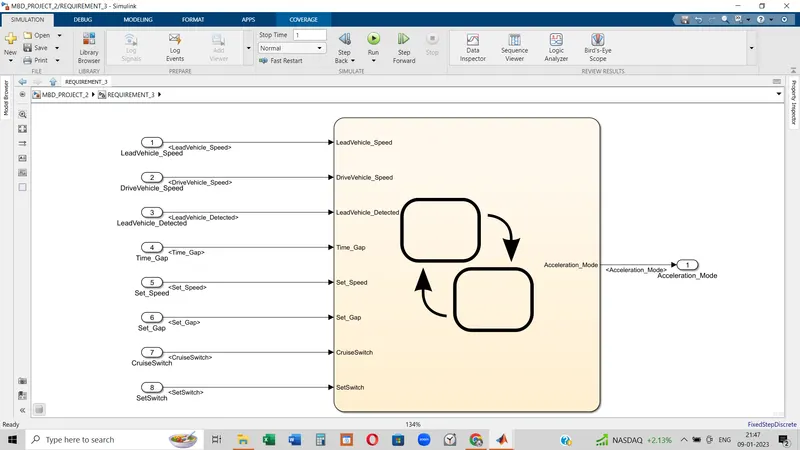
Inside the chart:
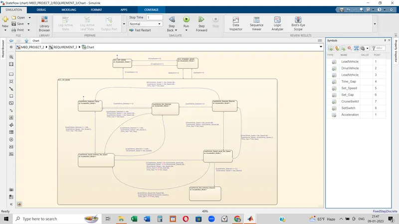
In Requirement_3, all the output signals have come as input and 5 more signals have been introduced as inputs here. Here the main operation will process by the instruction provided in Chart block. If Cruise Switch is equal to 0, the Acceleration mode will be Off and if Cruise Switch is equal to 1 the vehicle will go to the standby condition. Acceleration On mode will be activated when Set Switch is equal to 1 Otherwise the Acceleration mode will rely on either the Standby condition or Off condition.
- The Model:
- Requirement Tagging:
Requirement_1:
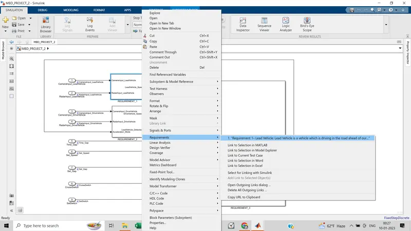
Requirement_2:
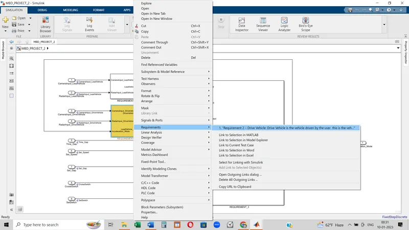
Requirement_3:
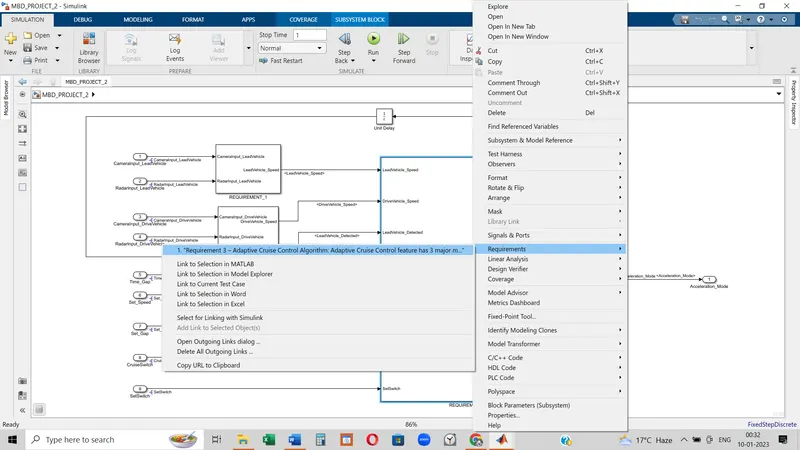
ACC_OFF_Mode(Inside the Requirement_3):
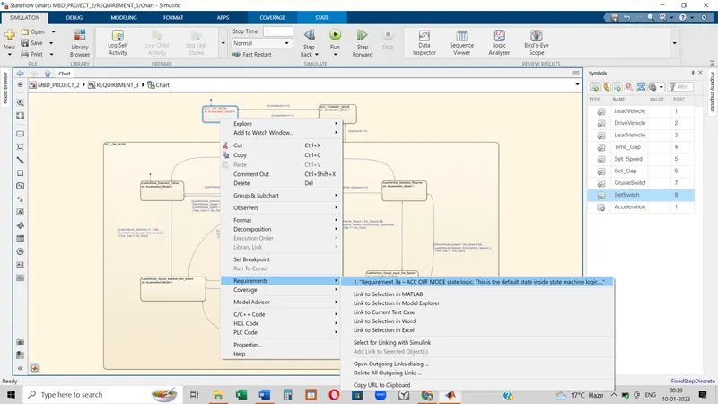
ACC_Standby_Mode(Inside the Requirement_3):
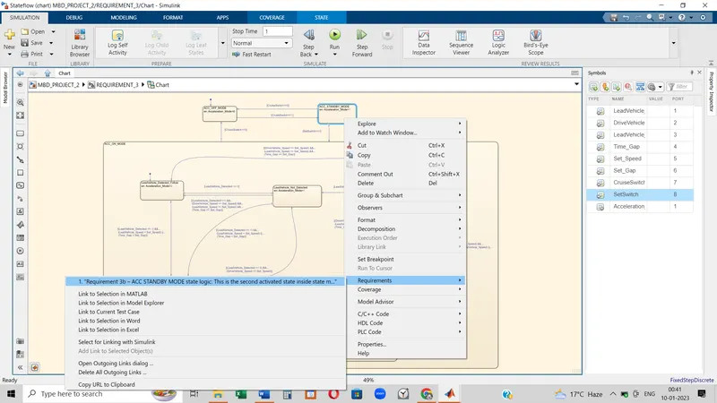
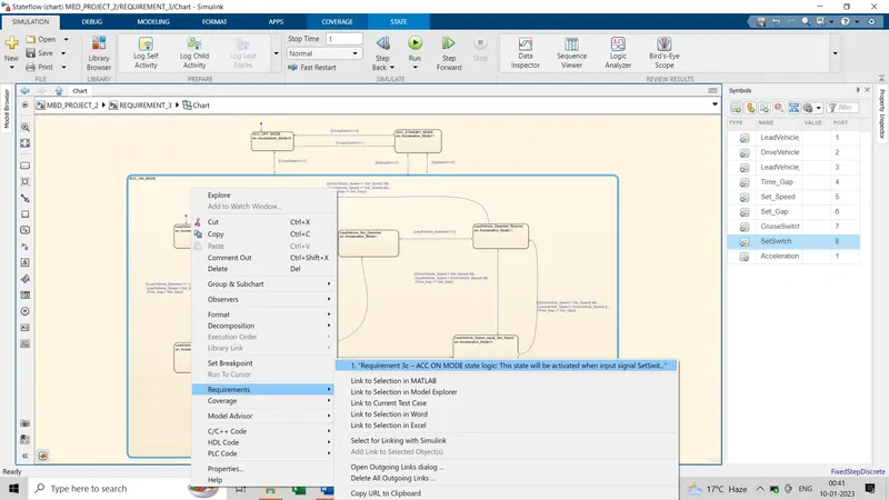
ACC_ON_Mode(Inside the Requirement_3):
- Resolving and Propagation:
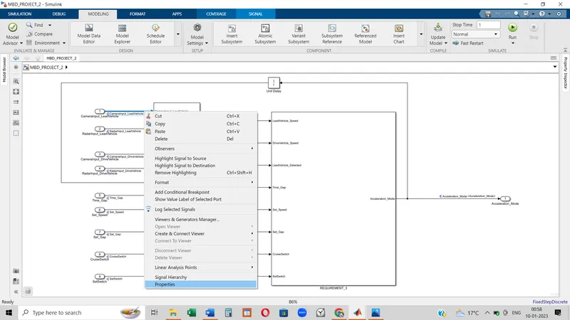
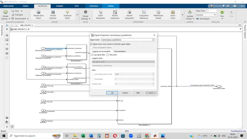
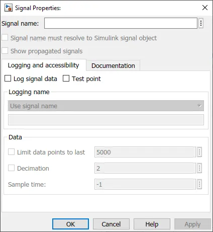 Right-click on the signal will through a pop-up where signal properties will come up. In the signal properties option, a window(on the left side) will be opened. We need to put the name of the input block at the source of the input signal and check the first box. Then the signal will be resolved. To propagate, we need to choose signals which are coming out from different blocks and have to check the box of 'Show propagated signal'.
- Model Advisor:
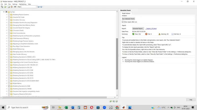
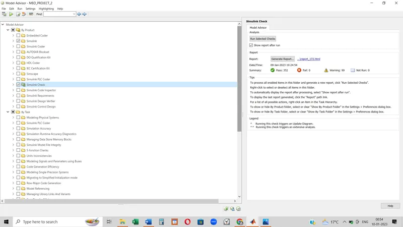
To choose the model advisor option first go to the modeling tab. On the left corner of the window, the model advisor option will appear.
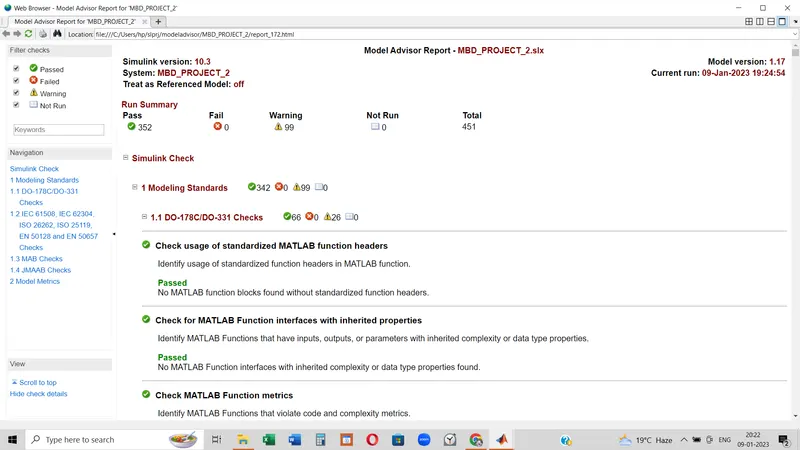
'By task' is concerned with the different guidelines and 'By-product' is associated with the checking requirement. Following are the different screenshots of choosing options by product and by task.
- Model Advisor report:
- Code Generation:
Before generating code we should update some configuration parameters.
- Generated Code:
/*
 * File: MBD_PROJECT_2.c
 *
 * Code generated for Simulink model 'MBD_PROJECT_2'.
 *
 * Model version                  : 1.18
 * Simulink Coder version         : 9.5 (R2021a) 14-Nov-2020
 * C/C++ source code generated on : Tue Jan 10 01:31:04 2023
 *
 * Target selection: ert.tlc
 * Embedded hardware selection: Intel->x86-64 (Windows64)
 * Code generation objectives: Unspecified
 * Validation result: Not run
 */

#include "MBD_PROJECT_2.h"
#include "MBD_PROJECT_2_private.h"

/* Named constants for Chart: '/Chart' */
#define IN_LeadVehicle_Detected_Follow ((uint8_T)1U)
#define IN_LeadVehicle_Detected_Resume ((uint8_T)2U)
#define IN_LeadVehicle_Not_Detected_Res ((uint8_T)4U)
#define IN_LeadVehicle_Speed_equal_Set_ ((uint8_T)5U)
#define IN_LeadVehicle_Speed_lessthan_S ((uint8_T)6U)
#define MBD_IN_LeadVehicle_Not_Detected ((uint8_T)3U)
#define MBD_PROJECT_2_IN_ACC_OFF_MODE  ((uint8_T)1U)
#define MBD_PROJECT_2_IN_ACC_ON_MODE   ((uint8_T)2U)
#define MBD_PROJECT_IN_ACC_STANDBY_MODE ((uint8_T)3U)
#define MBD_PROJECT__IN_NO_ACTIVE_CHILD ((uint8_T)0U)

/* Exported data definition */

/* Definition for custom storage class: ExportToFile */
uint8_T Acceleration_Mode;             /* '/Chart' */
uint8_T DriveVehicle_Speed;            /* '/Add' */
uint8_T LeadVehicle_Detected;          /* '/Signal Conversion' */
uint8_T LeadVehicle_Speed;             /* '/Add' */

/* Block states (default storage) */
DW_MBD_PROJECT_2_T MBD_PROJECT_2_DW;

/* Real-time model */
static RT_MODEL_MBD_PROJECT_2_T MBD_PROJECT_2_M_;
RT_MODEL_MBD_PROJECT_2_T *const MBD_PROJECT_2_M = &MBD_PROJECT_2_M_;
real_T rt_roundd_snf(real_T u)
{
  real_T y;
  if (fabs(u) < 4.503599627370496E+15) {
    if (u >= 0.5) {
      y = floor(u + 0.5);
    } else if (u > -0.5) {
      y = u * 0.0;
    } else {
      y = ceil(u - 0.5);
    }
  } else {
    y = u;
  }

  return y;
}

/* Model step function */
void MBD_PROJECT_2_step(void)
{
  int32_T tmp;
  int32_T tmp_0;
  uint8_T tmp_1;
  uint8_T tmp_2;

  /* Sum: '/Add' incorporates:
   *  Inport: '/CameraInput_LeadVehicle'
   *  Inport: '/RadarInput_LeadVehicle'
   */
  LeadVehicle_Speed = (uint8_T)((uint32_T)CameraInput_LeadVehicle +
    RadarInput_LeadVehicle);

  /* Sum: '/Add' incorporates:
   *  Inport: '/CameraInput_DriveVehicle'
   *  Inport: '/RadarInput_DriveVehicle'
   *  UnitDelay: '/Unit Delay'
   */
  DriveVehicle_Speed = (uint8_T)((uint32_T)(uint8_T)((uint32_T)
    CameraInput_DriveVehicle + Acceleration_Mode) + RadarInput_DriveVehicle);

  /* SignalConversion: '/Signal Conversion' incorporates:
   *  Inport: '/RadarInput_DriveVehicle'
   */
  LeadVehicle_Detected = RadarInput_DriveVehicle;

  /* Chart: '/Chart' incorporates:
   *  Inport: '/CruiseSwitch'
   *  Inport: '/SetSwitch'
   *  Inport: '/Set_Gap'
   *  Inport: '/Set_Speed'
   *  Inport: '/Time_Gap'
   */
  if (MBD_PROJECT_2_DW.is_active_c3_MBD_PROJECT_2 == 0U) {
    MBD_PROJECT_2_DW.is_active_c3_MBD_PROJECT_2 = 1U;
    MBD_PROJECT_2_DW.is_c3_MBD_PROJECT_2 = MBD_PROJECT_2_IN_ACC_OFF_MODE;
    Acceleration_Mode = 0U;
  } else {
    switch (MBD_PROJECT_2_DW.is_c3_MBD_PROJECT_2) {
     case MBD_PROJECT_2_IN_ACC_OFF_MODE:
      Acceleration_Mode = 0U;
      if (CruiseSwitch) {
        MBD_PROJECT_2_DW.is_c3_MBD_PROJECT_2 = MBD_PROJECT_IN_ACC_STANDBY_MODE;
        Acceleration_Mode = 1U;
      }
      break;

     case MBD_PROJECT_2_IN_ACC_ON_MODE:
      if (!CruiseSwitch) {
        MBD_PROJECT_2_DW.is_ACC_ON_MODE = MBD_PROJECT__IN_NO_ACTIVE_CHILD;
        MBD_PROJECT_2_DW.is_c3_MBD_PROJECT_2 = MBD_PROJECT_2_IN_ACC_OFF_MODE;
        Acceleration_Mode = 0U;
      } else if (!SetSwitch) {
        MBD_PROJECT_2_DW.is_ACC_ON_MODE = MBD_PROJECT__IN_NO_ACTIVE_CHILD;
        MBD_PROJECT_2_DW.is_c3_MBD_PROJECT_2 = MBD_PROJECT_IN_ACC_STANDBY_MODE;
        Acceleration_Mode = 1U;
      } else {
        switch (MBD_PROJECT_2_DW.is_ACC_ON_MODE) {
         case IN_LeadVehicle_Detected_Follow:
          Acceleration_Mode = 2U;
          if (LeadVehicle_Detected == 0) {
            MBD_PROJECT_2_DW.is_ACC_ON_MODE = MBD_IN_LeadVehicle_Not_Detected;
            Acceleration_Mode = 1U;
          } else if (((LeadVehicle_Detected == 1) && (LeadVehicle_Speed <
                       Set_Speed)) || (Time_Gap < Set_Gap)) {
            MBD_PROJECT_2_DW.is_ACC_ON_MODE = IN_LeadVehicle_Speed_lessthan_S;
            Acceleration_Mode = 4U;
          }
          break;

         case IN_LeadVehicle_Detected_Resume:
          Acceleration_Mode = 3U;
          if ((DriveVehicle_Speed == Set_Speed) && (LeadVehicle_Speed >=
               Set_Speed) && (Time_Gap >= Set_Gap)) {
            MBD_PROJECT_2_DW.is_ACC_ON_MODE = IN_LeadVehicle_Detected_Follow;
            Acceleration_Mode = 2U;
          } else if (LeadVehicle_Detected == 0) {
            MBD_PROJECT_2_DW.is_ACC_ON_MODE = MBD_IN_LeadVehicle_Not_Detected;
            Acceleration_Mode = 1U;
          } else if ((DriveVehicle_Speed < Set_Speed) && (LeadVehicle_Speed >
                      DriveVehicle_Speed) && (Time_Gap >= Set_Gap)) {
            MBD_PROJECT_2_DW.is_ACC_ON_MODE = IN_LeadVehicle_Speed_equal_Set_;
            Acceleration_Mode = 5U;
          }
          break;

         case MBD_IN_LeadVehicle_Not_Detected:
          Acceleration_Mode = 1U;
          if ((LeadVehicle_Detected == 1) && (DriveVehicle_Speed == Set_Speed) &&
              (LeadVehicle_Speed >= Set_Speed) && (Time_Gap >= Set_Gap)) {
            MBD_PROJECT_2_DW.is_ACC_ON_MODE = IN_LeadVehicle_Detected_Follow;
            Acceleration_Mode = 2U;
          } else if (((LeadVehicle_Detected == 1) && (LeadVehicle_Speed <
                       Set_Speed)) || (Time_Gap < Set_Gap)) {
            MBD_PROJECT_2_DW.is_ACC_ON_MODE = IN_LeadVehicle_Speed_lessthan_S;
            Acceleration_Mode = 4U;
          }
          break;

         case IN_LeadVehicle_Not_Detected_Res:
          Acceleration_Mode = 1U;
          break;

         case IN_LeadVehicle_Speed_equal_Set_:
          Acceleration_Mode = 5U;
          if ((LeadVehicle_Detected == 0) || (DriveVehicle_Speed <= Set_Speed))
          {
            MBD_PROJECT_2_DW.is_ACC_ON_MODE = IN_LeadVehicle_Not_Detected_Res;
            Acceleration_Mode = 1U;
          } else if (((DriveVehicle_Speed < Set_Speed) && (LeadVehicle_Speed >
                       DriveVehicle_Speed)) || (Time_Gap >= Set_Gap)) {
            MBD_PROJECT_2_DW.is_ACC_ON_MODE = IN_LeadVehicle_Detected_Resume;
            Acceleration_Mode = 3U;
          } else if (((LeadVehicle_Speed < Set_Speed) && (LeadVehicle_Speed <
                       DriveVehicle_Speed)) || ((int32_T)rt_roundd_snf(0.75 *
                       (real_T)Set_Gap) == Time_Gap)) {
            MBD_PROJECT_2_DW.is_ACC_ON_MODE = IN_LeadVehicle_Speed_lessthan_S;
            Acceleration_Mode = 4U;
          }
          break;

         default:
          /* case IN_LeadVehicle_Speed_lessthan_Set_Speed: */
          Acceleration_Mode = 4U;
          tmp = (int32_T)rt_roundd_snf((real_T)LeadVehicle_Speed * 1.25);
          tmp_0 = (int32_T)rt_roundd_snf(1.25 * (real_T)Set_Gap);
          if (tmp < 256) {
            tmp_1 = (uint8_T)tmp;
          } else {
            tmp_1 = MAX_uint8_T;
          }

          if (tmp_0 < 256) {
            tmp_2 = (uint8_T)tmp_0;
          } else {
            tmp_2 = MAX_uint8_T;
          }

          if ((tmp_1 >= DriveVehicle_Speed) && ((int32_T)rt_roundd_snf((real_T)
                LeadVehicle_Speed * 0.75) <= DriveVehicle_Speed) &&
              (DriveVehicle_Speed < Set_Speed) && (Time_Gap <= tmp_2) &&
              (Time_Gap >= (int32_T)rt_roundd_snf(0.75 * (real_T)Set_Gap))) {
            MBD_PROJECT_2_DW.is_ACC_ON_MODE = IN_LeadVehicle_Speed_equal_Set_;
            Acceleration_Mode = 5U;
          } else if ((LeadVehicle_Detected == 0) && (DriveVehicle_Speed ==
                      Set_Speed)) {
            MBD_PROJECT_2_DW.is_ACC_ON_MODE = MBD_IN_LeadVehicle_Not_Detected;
            Acceleration_Mode = 1U;
          }
          break;
        }
      }
      break;

     default:
      /* case IN_ACC_STANDBY_MODE: */
      Acceleration_Mode = 1U;
      if (!CruiseSwitch) {
        MBD_PROJECT_2_DW.is_c3_MBD_PROJECT_2 = MBD_PROJECT_2_IN_ACC_OFF_MODE;
        Acceleration_Mode = 0U;
      } else if (SetSwitch) {
        MBD_PROJECT_2_DW.is_c3_MBD_PROJECT_2 = MBD_PROJECT_2_IN_ACC_ON_MODE;
        MBD_PROJECT_2_DW.is_ACC_ON_MODE = IN_LeadVehicle_Detected_Follow;
        Acceleration_Mode = 2U;
      }
      break;
    }
  }

  /* End of Chart: '/Chart' */
}

/* Model initialize function */
void MBD_PROJECT_2_initialize(void)
{
  /* (no initialization code required) */
}

/* Model terminate function */
void MBD_PROJECT_2_terminate(void)
{
  /* (no terminate code required) */
}

/*
 * File trailer for generated code.
 *
 * [EOF]
*/ - Result:
So here I have come across the conclusion part. By changing the input values the result will be coordinated accordingly. From the SLDD file, we can change the input values and according to the values, acceleration will be initiated. Though the acceleration will be changed as per the sensor data, it is not liable to stop a car. Cruise Control is to provide an extra feature to drive a car. All the result files for a single input value including the model orientation have been attached in form of a code generation report file. The model is as per the MAAB guideline and the proper test report of the Model advisor has also been attached. A word file of requirement tagging is attached.
The attached files are:
- Simulink Model file
- SLDD file
- Model Advisor Report
- Generated Code file in ZIP format.
- Requirement tagging word file