Project-1: Powertrain for aircraft in runways
(1) Search and list out the total weight of various types of aircraft:
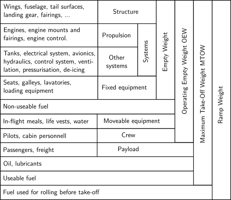
- Empty Weight (MEW): It is the weight of the aircraft “as built” and includes the weight of the structure, power plant (engines), furnishings, installations, systems, and other equipment that are considered an integral part of an aircraft.
- Zero Fuel Weight (ZFW): This is the total weight of the airplane and all its contents including unusable fuel (unusable fuel is the fuel that is required to maintain the structural stability of the aircraft, especially wings), but excluding the total weight of the usable fuel on board (usable fuel is the fuel necessary for the flight). Note: As a flight progresses and fuel is consumed, the total weight of the airplane reduces, but the ZFW remains constant.
- Operational Empty Weight (OEM) or Dry Operating Weight (DOW): It is the basic weight of an aircraft including the crew, all fluids necessary for operation, (such as engine oil, engine coolant, water, unusable fuel) all operator items and equipment required for flight but excluding usable fuel and the payload.
- Maximum Zero Fuel Weight (MZFW): Maximum zero fuel weight (MZFW) is the maximum weight allowed before usable fuel and other specified usable agents (engine injection fluid, and other consumable propulsion agents) are loaded. OR (OEM / DOW + Payload = MZFW)
- Maximum Taxi Weight (MTW) or Maximum Ramp Weight (MRW): It is the maximum permitted weight of the aircraft at which it may be moved on the ground either with its own engine or towed by a tractor. It can also be defined as the maximum weight for ground maneuvering including the weight of run-up and taxi fuel. (MZFE + Ramp Fuel = MRW)
- Maximum Take-Off Weight (MTOW): It is the maximum permitted weight at the start of the take-off. While determining this limit, the manufacturer takes into consideration the strength of the material used for the manufacturing of the aircraft and standard performance variables such as runway temperature, altitude, atmospheric pressure, wind components, flaps, etc. (MZFW + Take-Off Fuel = MTOW)
- Regulated Take-Off Weight (RTOW): As told in the above definition depending on different factors (e.g. flap setting, altitude, air temperature, length of the runway), RTOW, or maximum permissible takeoff weight varies for each takeoff. It can never be higher than MTOW.
- All Up Weight (AUP): DOW + Payload + Fuel.
- Maximum Landing Weight (MLW): When the aircraft touches the ground it puts the force of the runway as well as on the tires and undercarriage, so to ensure the structural safety of the aircraft MLW is taken into consideration. Manufacturers have calculated this force to be approximately “9” times the weight of the aircraft. Thus when the aircraft has to make an emergency landing or when the weight of the aircraft before landing exceeds the MLW, defined by the manufacturer, the pilots dump fuel to reduce the weight of the aircraft. (MTOW – Trip Fuel = MLW).
Lists of some common aircraft and their weights: (Ref:https://pilotteacher.com/)
| Aircraft | Empty Weight | Max Fuel Weight | Max Cargo Weight | Max Gross Takeoff Weight |
|---|---|---|---|---|
| Antanov AN-225 | 628,000 lbs 285,000 kg |
661,400 lbs 300,000 kg |
417,000 lbs 190,000 kg |
1,411,000 lbs 640,000 kg |
| Airbus A380-800 | 611,000 lbs 277,000 kg |
560,000 lbs 254,000 kg |
185,000 lbs 84,000 kg |
1,268,000 lbs 575,000 kg |
| Boeing 747-800 | 485,300 lbs 220,100 kg |
427,400 lbs 194,000 kg |
295,000 lbs 134,000 kg |
987,000 lbs 447,700 kg |
| Airbus A340-500 | 370,000 lbs 168,000 kg |
386,300 lbs 175,000 kg |
119,000 lbs 54,000 kg |
820,000 lbs 372,000 kg |
| Boeing 777-300ER | 370,000 lbs 168,000 kg | 320,800 lbs 145,500 kg | 148,000 lbs 67,100 kg |
776,000 lbs 352,000 kg |
| Boeing 787-10 | 299,000 lbs 135,500 kg | 223,500 lbs 101,500 kg |
126,300 lbs 57,300 kg | 560,000 lbs 254,000 kg |
| Boeing 737-900 | 98,500 lbs 44,700 kg |
53,100 lbs 24,000 kg |
44,600 lbs 20,200 kg |
187,000 lbs 85,000 kg |
| Airbus A320-100 | 93,900 lbs 42,600 kg |
48,700 lbs 22,100 kg |
44,000 lbs 20,000 kg |
150,000 lbs 68,000 kg |
| Embraer 190 | 63,500 lbs 28,800 kg |
28,600 lbs 13,000 kg |
28,800 lbs 13,100 kg |
106,000 lbs 48,000 kg |
| Gulfstream G650 | 54,000 lbs 24,500 kg | 48,200 lbs 21,900 kg | 6,500 lbs 3,000 kg |
100,000 lbs 45,200 kg |
| Bombardier CRJ900 | 48,160 lbs 21,850 kg | 19,600 lbs 8,900 kg | 6,075 lbs 2,760 kg | 80,500 lbs 36,500 kg |
| Bombardier Q400 | 39,300 lbs 17,800 kg |
11,700 lbs 5,300 kg |
18,700 lbs 8,500 kg |
62,000 lbs 28,000 kg |
| Learjet 75 | 13,900 lbs 6,300 kg | 6,060 lbs 2,750 kg |
2,900 lbs 1,300 kg |
21,500 lbs 9,700 kg |
| Cessna Citation CJ4 | 10,300 lbs 4,700 kg | 5,800 lbs 2,650 kg |
2,200 lbs 1,000 kg | 17,200 lbs 7,800 kg |
| Beechcraft King Air B100 | 7,100 lbs 3,200 kg | 3,200 lbs 1,450 kg |
4,150 lbs 1,900 kg |
12,000 lbs 5,400 kg |
| Diamond DA50 RG | 3,200 lbs 1,450 kg |
340 lbs 155 lbs |
1,250 lbs 560 kg |
4,400 lbs 2,000 kg |
| Beechcraft Bonanza G36 | 2,500 lbs 1,150 kg | 450 lbs 200 kg |
850 lbs 385 kg |
3,660 lbs 1,660 kg |
| Cessna 206H | 2,200 lbs 990 kg |
520 lbs 235 kg |
1,150 lbs 520 kg |
3,600 lbs 1,630 kg |
| Sirrus SR22 | 2,250 lbs 1,000 kg | 485 lbs 220 kg |
950 lbs 430 kg |
3,600 lbs 1,630 kg |
| Cessna 172R | 1,700 lbs 770 kg |
380 lbs 170 kg |
560 lbs 255 kg |
2,425 lbs 1,100 kg |
(2)Difference between ground speed and air speed:
What is Ground Speed: Ground speed is the horizontal speed of an aircraft relative to the Earth’s surface.
- Suppose we take a point 'x' on the ground. Now the speed of aircraft in respect of the point 'x' is the Ground Speed.
- Ground speed is the vector quantity.
- a comparison of the ground speed to the wind speed must be done according to rules for vector comparison.
Now, Before understanding the Air speed, we need to have a proper idea of the wind speed. Because it is impossible to clarify the term Air speed without knowing the Wind Speed.
What is Wind Speed: According to the NASA guideline, for a reference point picked on the ground, the air moves relative to the reference point is the wind speed.
- Air: The gaseous mixture in our atmosphere is called air.
- Wind: Wind is the horizontal motion of air, due to the pressure difference between two places.
- As we took a reference point 'x' on the ground, now the speed at which the air moves in respect of the 'x' point is called the Wind speed.
- It is also a vector quantity.
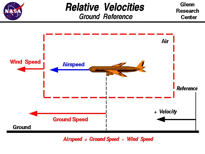
- The wind has three components in three primary directions those are north-south, east-west, and up-down. In this figure, we are considering only velocities along the aircraft's flight path(East-West). A positive velocity is defined to be in the direction of the aircraft's motion. We are neglecting cross winds(North-South), which blow perpendicular to the flight path, and upward-downwards which also occur perpendicular to the ground.
What is Air Speed: The relative velocity between the object or the aircraft and the air(or more specifically wind) is called the airspeed.
- Airspeed cannot be directly measured from a ground position. It should be calculated from the ground speed and the wind speed.
- Airspeed is the vector difference between the ground speed and the wind speed.
- Let, Ground Speed= Vg and Wind speed= Vw
So, Air speed= (→Vg)-(→Vw).
Wind speed vs Air Speed:
- Wind speed is an independent parameter where air speed depends on wind and ground speed.
- Wind speed is calculated to the reference point of ground but Air speed calculation does not depend upon any reference point directly.
- On a perfectly still day, the airspeed is equal to the ground speed because on a perfectly still day wind speed is zero. (which is impractical).
- But in practice, if the wind is blowing in the same direction that the aircraft is moving, the airspeed will be less than the ground speed. For example, If the Ground speed is 100 kmph and the wind speed is 70 kmph, the Air speed=(100-70)=30 kmph, which is less than the Ground speed.
(3) Why is it not recommended to use aircraft engine power to move it on the ground at Airport :
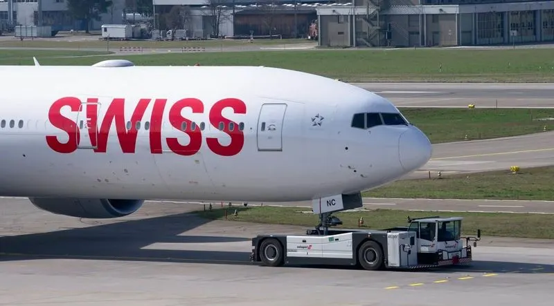
There are several reasons to use towing equipment to move aircraft in airports.
- To abolish hazardous conditions at the airport: When the aircraft engine gets ON, the propeller starts to rotate and it creates a thrust. (Thrust is the force that moves an aircraft through the air. Thrust is used to overcome the drag of an airplane, and to overcome the weight of a rocket.). As a result of it, the high-speed wind is generated which can damage airport property, surrounding ground vehicles, other jetways, or ground personnel. In fact of the high wind speed, dust particles, and debris creates an inferior atmosphere and enters the engine and vandalize it.
- To minimize the noise: Due to thrust or propeller, an extreme noise generates which could be hazardous for ground personnel.
- A cost-effective way to send for maintenance: When an aircraft needs to be moved to a hangar for maintenance purposes the easiest way is to send an aircraft tug to the tow-in gate for transport. It's also not cost-efficient to start aircraft engines just to reposition an aircraft for maintenance purposes. Typically, ground personnel is trained to only need the aircraft brake system when towing a large aircraft.
- Pilots have limited visibility from the cockpit to ground: Pilots do not have a clear view of the rear from the flight deck and thus rely on aircraft towing equipment for ground pushback when needed. Once the aircraft is perfectly positioned and far from the terminal tow-in gate and other vehicles, the airport tug is disconnected and the aircraft can use its engines and steering to move to the runway for takeoff.
- For reverse movement: Planes are not designed to move in backward. So in that situation aircraft tug is the only option to move in the reverse direction in the taxiway.
(3) How an aircraft is pushed to runway when its ready to take off:
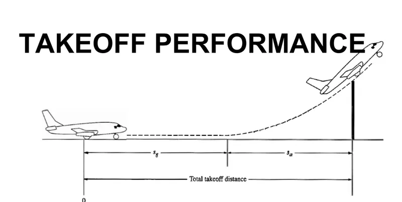
- An airplane is motionless at the end of a runway. This is denoted by location O. The pilot releases the brakes and pushes the throttle to maximum takeoff power, and the airplane accelerates down the runway. At some distance from its starting point, the airplane lifts into the air. The distance the airplane cover along the runway before it lifts into the air is called the ground roll (sg). The total takeoff distance also includes the extra distance covered over the ground after the airplane is airborne but before it clears an obstacle of 50 ft for military aircraft and 35 ft for commercial aircraft. This is denoted by sa. The sum of sg and sa is the total takeoff distance.
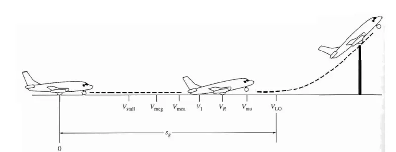
- As the airplane accelerates from zero velocity, at some point it will reach the stalling velocity VStall.
- The airplane continues to accelerate until it reaches the minimum control speedon the ground, Vmcg. This is the minimum velocity at which enough aerodynamic force can be generated on the vertical fin with rudder deflection while the airplane is still rolling along the ground to produce a yawing moment sufficient to counteract that produced when there is an engine failure for a multiengine aircraft.
- If the airplane were in the air (without the landing gear in contact with the ground), the minimum speed required for yaw control in case of engine failure is slightly greater than Vmcg This velocity is called the minirnum control speed in
the air, Vmca. - The airplane continues to accelerate until it reaches the decision speed, V1. This is the speed at which the pilot can successfully continue takeoff even though an engine failure (in a multi-engine aircraft) would occur at this point. If an engine fails before V1 is achieved, the takeoff must be stopped. If an engine fails after V1 is reached, the takeoff has to be completed.
- The airplane continues to accelerate until the takeoff rotational speed, VR is achieved. At this velocity, the pilot initiates by elevator deflection a rotation of the airplane in order to increase the angle of attack and to overcome the weight. Attention should be paid not to stall.
- the angle of attack necessary to overcome the weight may not be achievable because the tail may drag the ground. If the rotation of the airplane is limited by ground clearance for the tail, the airplane must continue to accelerate while rolling along the ground after rotation is achieved. This speed is called the minimum unstick speed, denoted by Vus.
- For increased safety, the angle of attack after rotation is slightly less than the maximum allowable by tail clearance, and the airplane continues to accelerate to a slightly higher velocity, called the lift off speed, denoted by VLO. This is the point at which the airplane actually lifts off the ground. The total distance covered along the ground to this point is the ground roll sg.
- Generally VLO=1.1 Vstall
- It is calulated by,
m*(dv/dt) = T-D-R. [where m=mass of aircraft, dv/dt= change of velocity, T=Thrust, D= Aerodynamic Force, R=Rolling resistance force.
5. Learn about take-off power, tire design, rolling resistance, tire pressure, and brake forces when landing :
i)Take-off Power:
The amount of power that an engine is allowed to produce for a limited period of time for takeoff. The use of takeoff power is usually limited to 5 min for reciprocating engines and up to 2½ min for gas turbine engines. This may not always be the case. Specifically, with respect to reciprocating engines, it is the brake horsepower developed under standard, sea-level conditions and under the maximum conditions of the crankshaft rotational speed and the engine manifold pressure approved for the normal take off.
It is limited in continuous use to the period of time shown in the approved engine specifications. With respect to gas turbine engines, it is the thrust developed under static conditions at a specified altitude and atmospheric conditions of the rotor shaft rotational speed and gas temperature approved for the normal takeoff.
- Disadvantages for using full power on takeoff is higher fuel consumption, noise, and engine wear.Instead, takeoff performance is calculated and the appropriate thrust setting is used.
- You need lower setting if:
- runway is long
- no obstacle to clear during climb
- runway is dry
- temperature is low
- headwind is fast
- airport is low (altitude)
All the above would increase your allowed payload and/or fuel load, and/or allow reduced thrust.
ii) Tyre Design:
When it comes to safety, tyres are one of the most important components of aircraft. They help to absorb the shock of landing and provide cushioning. It also provides the necessary traction for braking and stopping of an aircraft. An aircraft tyre is designed to withstand extremely heavy loads while landing, take off, taxing, and parking. The number of wheels required for aircraft increases with the weight of the aircraft, as the weight of the aeroplane needs to be distributed more evenly.
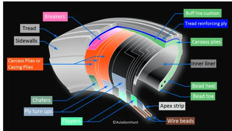
- Design and construction Carcass plies are used to form the tire. They are sometimes called casing plies. An aircraft tyre is constructed for the purpose it serves. 1.They support the weight of an aircraft while it is on the ground. 2.It also provides the necessary traction for braking and stopping of an aeroplane. 3.Tyre also helps to absorb the shock of landing and provide cushioning the roughness of takeoff, roll-out, and taxi operations. Unlike an automobile or truck tyre, it does not have to carry a load for a long period of continuous operation.
- Aircraft tyres may be tube-type or tube-less Tubeless tyres are more advantageous over tube-type. There is no longer the use of tube-type tyre in recent aviation. Nowadays all airliners are using tubeless tyres. Tubeless that are meant to be used without a tube has the word TUBELESS on the sidewall of the tyre.
-
Purpose of Chines Chines are also called deflectors. Chine tyre used on the nose wheel of aircraft, specially fuselage-mounted jet engines. It diverts runway water away from the engine inlets. Chines are circumferential protrusions that are moulded into the sidewall of nose tyres that deflect water sideways to help reduce excess water ingestion into the engines. Tyres may have chines on one or both sides, depending on the number of nose tyres on the aircraft.
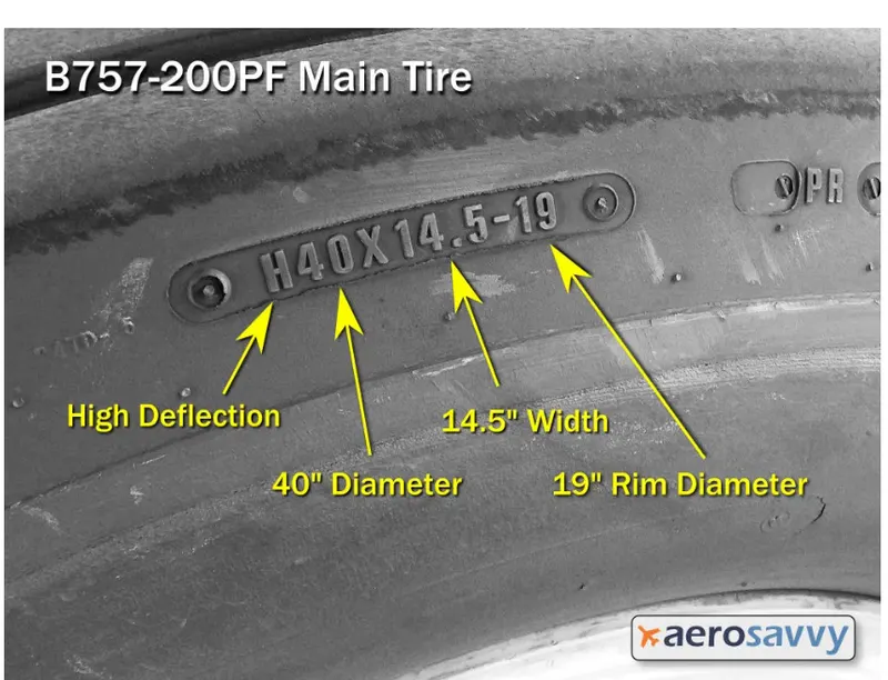
- Aircraft Tyre specification example:
iii) Rolling Resistance:
The force that resists the motion of a body rolling on a surface is called the rolling resistance or the rolling friction. Rolling resistance depends on air pressure in tires, the wear and tear of tires, and road.
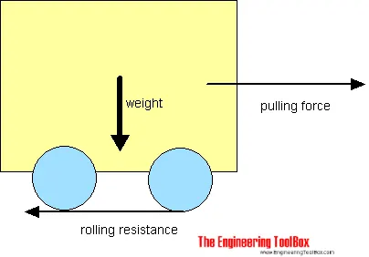
The rolling resistance can be expressed by the generic equation Fr = c W
where, Fr = rolling resistance or rolling friction (N, lbf)
c = rolling resistance coefficient - dimensionless (coefficient of rolling friction - CRF)
W = m ag
If the vehicle is rolling on a road with the gradient α [°], then the formula for rolling resistance becomes:
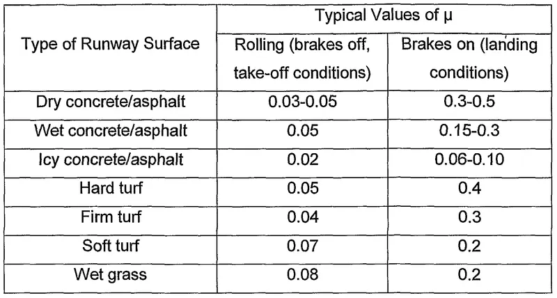
Rolling Friction Coefficients
Some typical rolling coefficients:
iv)Tyre pressure:
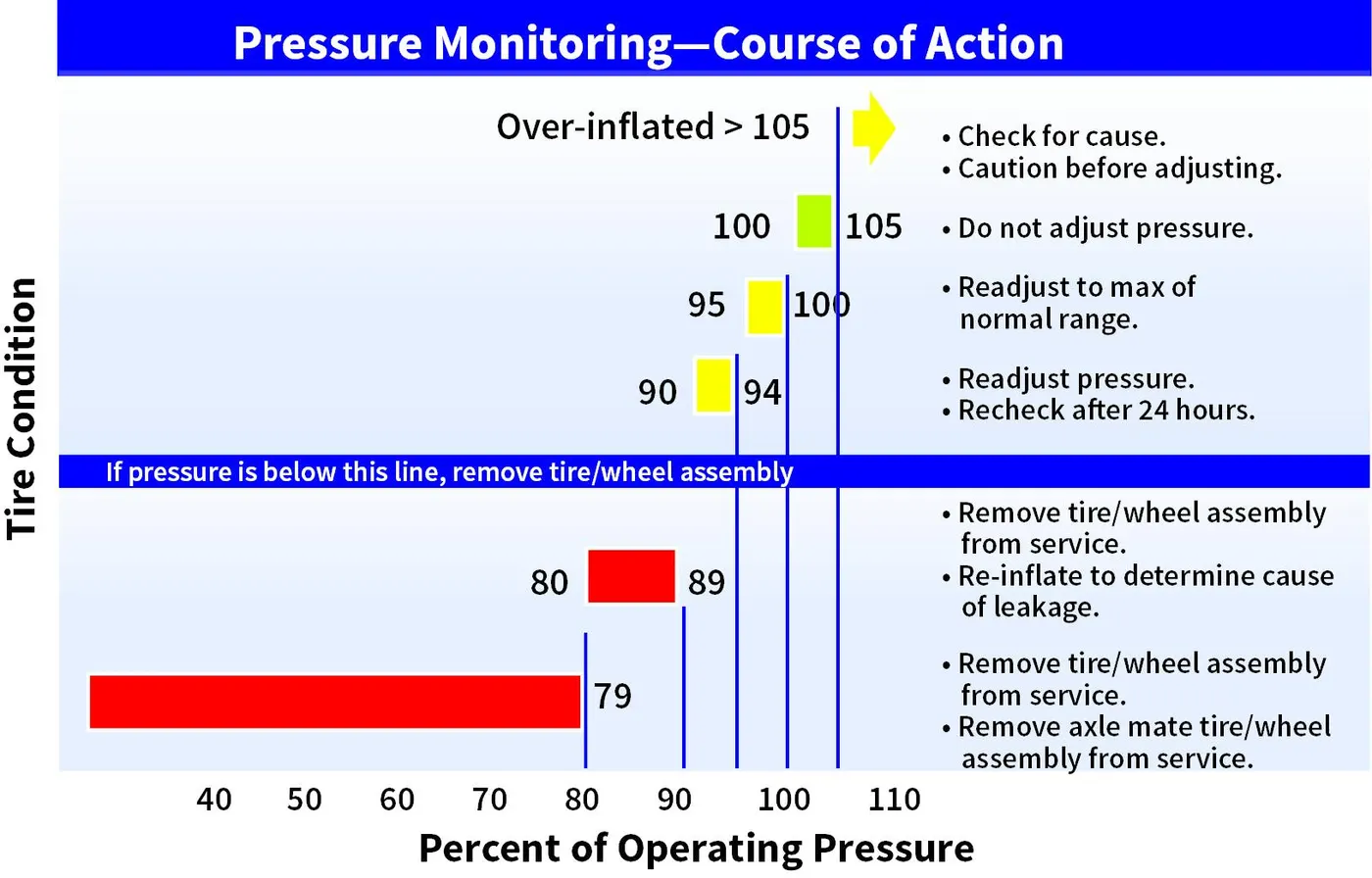
Aircraft tires operate at such high extremes of pressure, load, and speed, their care and service is critically important. The most important action an operator can take to prevent tire-related events is to maintain proper tire inflation pressure. Failure to keep aircraft tires properly inflated can lead to very serious consequences. The most serious of these is the structural failure of the tire.
- If the tire operates underinflated or overdeflected/overloaded, the nylon cords which form the structure of the tire go in and out of compression as the tire rotates. This weakens the cords – much like a paperclip which is bent back and forth – until eventually the cords break. If enough cords break, the entire structure will eventually fail. This particular break damaged the inner liner, allowing air to migrate through the tire to the atmosphere.
- Another serious consequence of under-inflation is the thrown tread. Overdeflection increases shear between components in the tire as it rolls in and out of contact and deforms. This results in a more rapid build‐up of heat within the tire than would be evident if the tire were properly inflated. At some point the excessive heat will cause the rubber to revert, or reverse cure. This reverted rubber is like grease with no strength or adhesion to contain the structure. This can allow the tire to decompose, throwing the entire tread or pieces of it. In addition to destroying the tire, thrown treads often result in expensive aircraft damage.
- In order to ensure that an aircraft’s tires are properly inflated, it is recommended to check the inflation pressure, with a calibrated gauge, before the first flight of the day or before each flight if not flown daily. Why is it important to check the pressure every day? Because of the high pressures and extreme temperatures at which aircraft tires operate, they do not hold air perfectly. In fact, an aircraft tire can lose up to 5 percent of its pressure in 24 hours and still be perfectly serviceable.
- When servicing tires, it is important to think about ambient temperature change. For every 5 F (3 C) change in temperature, there is a corresponding 1 percent change in tire pressure. If, for example, a tire is serviced in Miami where it is 85 F and the plane flies to Minneapolis where it is 25 F, a tire which was serviced to 100% of operating pressure, will be at 88 percent in Minneapolis (after cooling for three hours). If a mechanic checks the pressure in Minneapolis before the plane returns to Miami, the tire will be unserviceable and need to be changed. This is another reason Michelin recommends servicing the tires to the top of the acceptable range (105 percent of operating pressure). If this same tire had been serviced to 105 percent in Miami, it would have been at 93 percent in Minneapolis and still serviceable.
v) Brake forces when landing:
Airplanes rely on a braking system to safely land on runways. At cruising altitude, most commercial airplanes fly at a speed of roughly 500 to 600 mph. When landing, however, they must reduce their speed. A typical 747, for instance, has a landing speed of about 160 to 170 mph. And upon touching the runway, airplanes must quickly brake until they come to a complete stop. How do airplanes brake when landing exactly:
- Wing Brakes: Many airplanes use wing spoilers to assist with braking when landing. Not to be confused with ailerons, spoilers are extendable flaps on the ends of an airplane’s wings. Pilots can raise the spoilers to decelerate the airplane as it approaches the runway. And even while on the runway, pilots will typically leave the wing spoilers raised. Raised wing spoilers create drag, which essentially slows down the airplane so that it’s able to brake more quickly.
- Disc Brake: In addition to wing spoilers, airplanes use disc brakes. Airplane disc brakes are similar to the braking system in automobiles. They consist of a pair of calipers that, when engaged, squeeze pads against the rotors of an airplane’s landing gear. Disc brakes are designed to remain static at all times. In other words, they don’t rotate with the wheels of an airplane’s landing gear. As the wheels turn, the disc brakes will remain static and stationary. They are a vital component of an airplane’s braking system because they are designed to apply pressure to the airplane’s wheels. Disc brakes will squeeze the wheels, thereby slowing down the speed at which they spin. In turn, this reduces the speed of the airplane so that it can come to a complete stop on the runway.
- Reverse Thrust : Finally, many jet airplanes use reverse thrust to assist with braking during landings. Reverse thrust is a feature in jet engine airplanes that, as the name suggests, involves the reversal of the engines’ thrust. When flying, the thrust is projected out the rear of an airplane’s engines. When landing, however, pilots may use the reverse thrust feature. Reverse thrust changes the direction of the engines’ thrust. Rather than projecting out the rear, the thrust will be projected out the front. This reversal of thrust provides deceleration that allows airplanes to slow down more quickly when landing.
6. A. With necessary assumptions, calculate the force and power required to push/pull an aircraft by a towing vehicle:
The force that will be acted to push or pull an aircraft by a towing vehicle are Aerodynamic Drag Force, and Rolling Resistance Force.
Hill Climbing Force should not be considered here as it moves in angle less surface.
Aerodynamic Force Calculation formula: F(ad)=0.5*ρ*Cd*A*v^2
where, F(ad)= Aerodynamic Force
ρ= Air density
Cd= Drag co-efficient
A= Frontal area
v=velocity
Rolling Resistance Force calculation formula: F(rr)= µ(rr)*m*g
where, µ(rr)=Rolling resistance co-efficient
m= mass of vehicle
g= gravitational accelartion
F(rr)= Rolling Resistance Force
Assumption:
Considering Avanton AN-225 airplane:
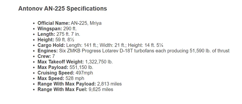
Aircraft mass= 771600 ln = 349991 Kg
Towing vehicle weight = 1000 Kg
ρ= Air density = 1.125 kg/m^3
Cd= Drag co-efficient = 0.15
A= Frontal area = 135 sqm
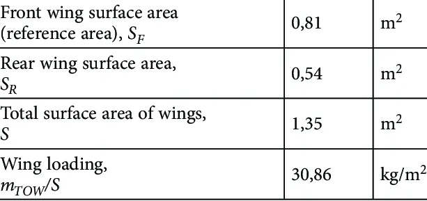
v=velocity= 12 kmph = 3.33 mps
µ(rr)=Rolling resistance co-efficient = 0.025 (Tar macadam)
g= gravitational accelartion = 9.8 m/s^2
Now,
F(ad)= 0.5* 1.125*0.15*135*(3.33)^2
= 126.30 N
Rolling Resistance Force of Aircraft, F1(rr) +Rolling Resistance Force of towing vehicle, F2(rr)
= 0.025*(349991.87+1000) *9.8
= 85992.7 N
Total Force acted = (126.30+85992.7)
=86119.10 N
=86.11 KN
Power required = Force * velocity
= 86.11 * 3.33
= 286.77 KW
6.B. Develop the model for the calculated force and power using Simulink:
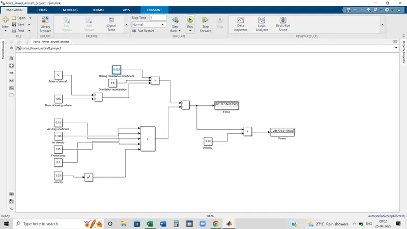
Blocks Used:
Few basic blocks has been used here. Those are following:
1. Constant
2. Sum
3. Product
4. Square
5. Display.
Explanation:
- As here only two forces are acted to push or pull the aircraft by towing the vehicle so we have to calculate two forces and by summing up we can get total force.
- We know, that Force x velocity = Power, so by multiplying the velocity with Force we will calculate the Power required to pull or push the aircraft.
- First, To measure the Rolling resistance force, F(rr)= µ(rr)*m*g, used four constant blocks, one sum block and one product block. Two constant blocks are provided for putting the mass of aircraft and towing vehicles. By Sum block, added two masses. Other two constant blocks for Rolling resistance co-efficient and gravitational acceleration. Lastly to calculate the Rolling resistance force, multiplied total mass, rolling resistance coefficient, and gravitational acceleration.
- Now come to the second force which is the Aerodynamic drag force. The formula is F(ad)=0.5*ρ*Cd*A*v^2. To measure it, used five constant blocks, and one square block. Constant blocks are for one, constant value of the formula, 0.5. two, aerodynamic drag coefficient, third, air density, and fourth, velocity. As per the formula, square value of velocity will be multiplied by other parameters. That's why one square block is used to get the square value of velocity. By using multiplication block, multiplied parameters and get the Aerodynamic Force.
- To get total force, added two separate forces by Sum block. Here a scope is connected to seeing the Force value.
- To calculate the power requirement, Force and velocity should be multiplied. So from the force path, one line is connected to the multiplication block and one separate constant block is used for velocity. Multiplied two values by using a multiplication block.
- Next, by connecting the display block to the multiplication block we can see the measurement of the power requirement.
7. A. Design an electric powertrain with type of motor, it’s power rating, and energy required to fulfill aircraft towing application in Simulink. Estimate the duty cycle range to control the aircraft speed from zero to highest. Make all required assumptions. Prepare a table of assumed parameters. Draw a block diagram of powertrain :
Based on the calculation,
- The required force to push/pull the aircraft = 86.11 KN
- Required Power = 286.77 KW
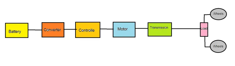
Now if assume,
Wheel diameter = 24 inch
so the radius will be = 24/2 = 12 inch
=0.304 meter
Gear ratio = 10
So,
Required Torque in wheel = Force * wheel radius
= 86.11 * 0.304
=26.18 KNm
Motor Torque = Wheel torque/gear ratio
= 26.18 * 10
=2.618 KNm
If time taken to complete the operation is 20 minutes(0.33 hours) so the energy requirement= 286.77 KW * 0.33 Hour = 95.59 KWh
Duty Cycle = Power required/Rated Power = 286.77/350 = 81.93 = almost equals to 82 %.
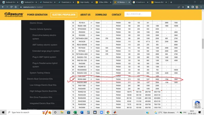
- As per the market availability of the motor, 350 KW BLDC will be suitable for this application.
- Required power for pulling or pushing aircraft is 286.77 KW. As the 350 KW is available in the market so to determine duty cycle
output power/rated power calculation is done. and the duty cycle is 82 %.
- So to control the vehicle from zero to the highest speed, the controller should be varied from 0 to 82% duty cycle value.
Parameters assumption:
| Sl No | Parameters | Values |
| 1 | Aircraft mass | 349991 Kg |
| 2 | Towing Vehicle mass | 1000 Kg |
| 3 | Rolling Resistance Co-efficient | 0.025 |
| 4 | Air drag Coefficient | 0.15 |
| 5 | Air density | 1.125 kg/m^3 |
| 6 | Velocity | 3.33 mps |
| 7 | Operation time | 20 min = 0.33 hour |
| 8 | Wheel radius | 12 inch = 0.308 meter |
| 9 | Gear ratio | 10 |
Powertrain design in Simulink (DC7 model):
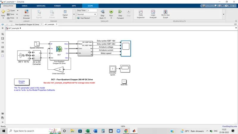
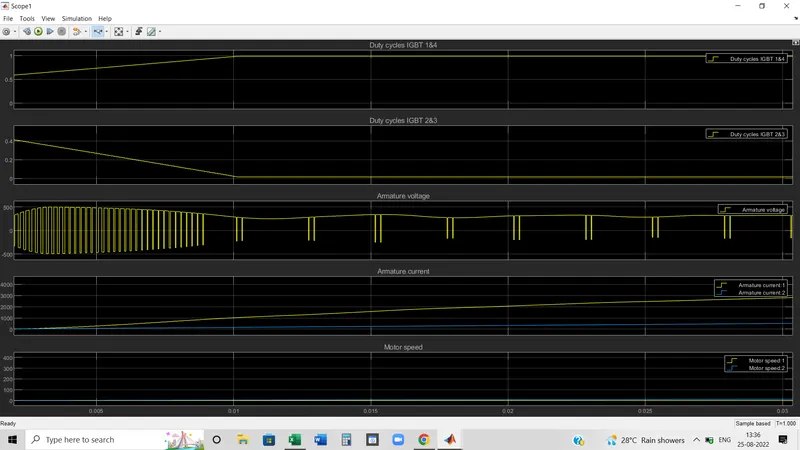
Result:
7. B. Design the parameters in excel sheet :
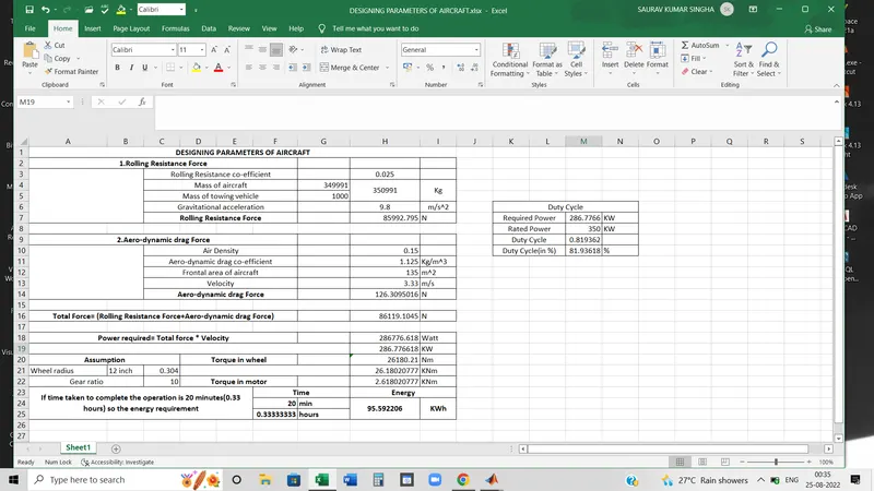
Excel file has been attached.