Week-7 Challenge: DC Motor Control
(1)
(1.A)
H-Bridge Circuit:
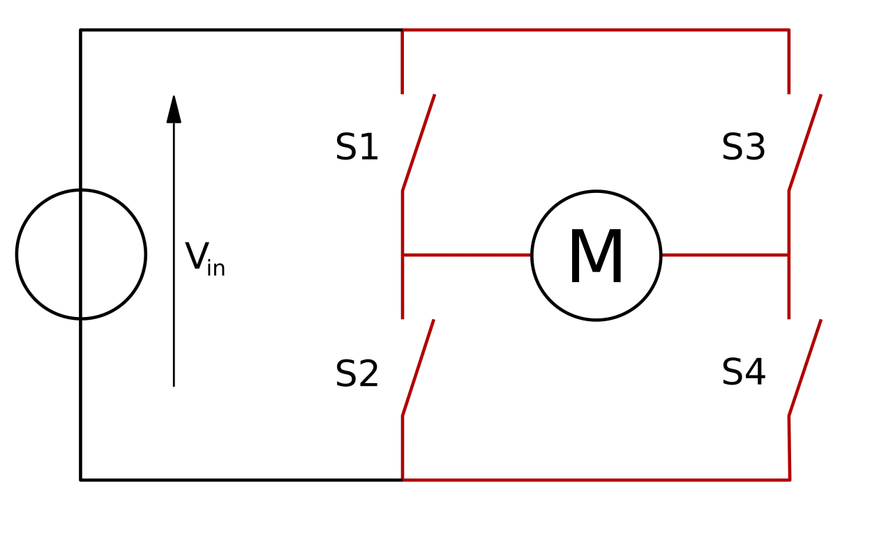
A H-bridge is an electronic circuit that switches the polarity of a voltage applied to a load. These circuits are often used in robotics and other applications to allow DC motors to run forwards or backward. The name is derived from its common schematic diagram representation, with four switching elements configured as the branches of a letter "H" and the load connected as the cross-bar.
Working of H-Bridge:
The term H-bridge is derived from the typical graphical representation of such a circuit. An H-bridge is built with four switches (solid-state or mechanical). When the switches S1 and S4 (according to the first figure) are closed (and S2 and S3 are open) a positive voltage is applied across the motor. By opening S1 and S4 switches and closing S2 and S3 switches, this voltage is reversed, allowing reverse operation of the motor.
Using the nomenclature above, the switches S1 and S2 should never be closed at the same time, as this would cause a short circuit on the input voltage source. The same applies to switches S3 and S4. This condition is known as shoot-through.
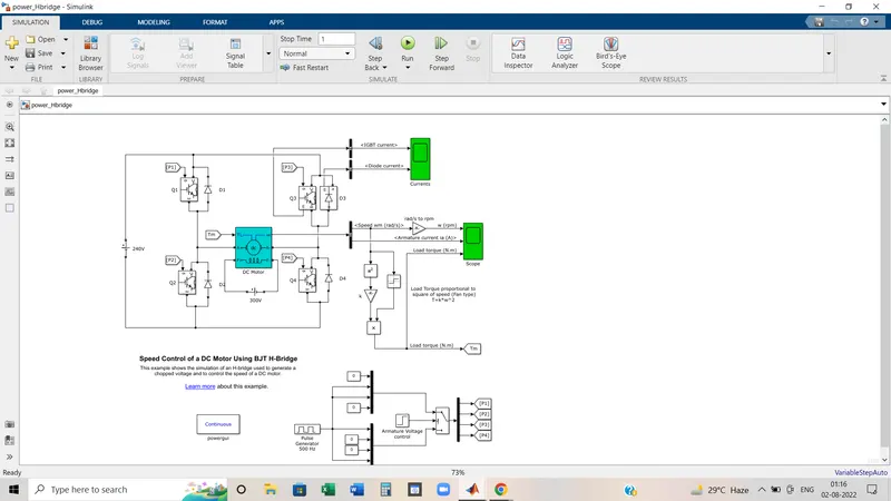
MATLAB model ‘Speed control of a DC motor using BJT H-bridge’ :
Description of model:
The Bipolar Junction Transistor (BJT) when used for power switching applications, operates as an IGBT. When it is conducting (BJT operating in the saturated region), a forward voltage Vf is developed between collector and emitter (in the range of 1 V). Therefore, the IGBT block can be used to model the BJT device.
The IGBT block does not simulate the gate current controlling the BJT or IGBT. The switch is controlled by a Simulink® signal (1/0). The DC motor uses the preset model (5 HP 24V 1750 rpm). It simulates a fan-type load (where Load torque is proportional to the square of speed). The armature mean voltage can be varied from 0 to 240 V when the duty cycle (specified in the Pulse Generator block) is varied from 0 to 100%.
The H-bridge consists of four BJT/Diode pairs (BJT simulated by IGBT models). Two transistors are switched simultaneously: Q1 and Q4 or Q2 and Q3. When Q1 and Q4 are fired, a positive voltage is applied to the motor and diodes D2-D3 operate as free-wheeling diodes when Q1 and Q4 are switched off. When Q2 and Q3 are fired, a negative voltage is applied to the motor and diodes D1-D4 operate as free-wheeling diodes when Q2 and Q3 are switched off.
How the model is working:
- In the H-Bridge circuit, a motor is at the center and four IGBT switches name Q1,Q2,Q3,Q4 are connected. Pulses P1,P2,P3,P4 are the corresponding inputs of the IGBT switches.
- A 300V supply is connected with the motor field in parallel to act as an electromagnet.
- 240 V supply is connected with motor armature circuit along with inverter circuit.
- Tm is the load torque applied to the motor for mechanical reference.
- One scope is for the graph of current of IGBT and Diode which are actually working as the switches.
- From the Bus selector, two output has come out as Motor speed(RPM) and Armature current.
- As we know the Torque value is the multiplication of the torque constant and the square of motor speed. As per the equation, another output as Load Torque has been connected with Scope_2 to see the result respectively motor speed, armature current, and Load Torque.
- In the first state, Q1 and Q4 are closed.By giving 1V to IGBT current from battery, passes through Q1 and Q4. Diode D2,D3 are used as free wheeling diode in this state.In this case Forward motoring and forward breaking are held.
- In Second state,Q2 and Q3 are closed by giving 1V to IGBT's,current from the battery, passes through Q2 and Q3. Diode D1, and D4 are used as free wheeling diodes in this state. In this case, reverse motoring and reverse braking are held.
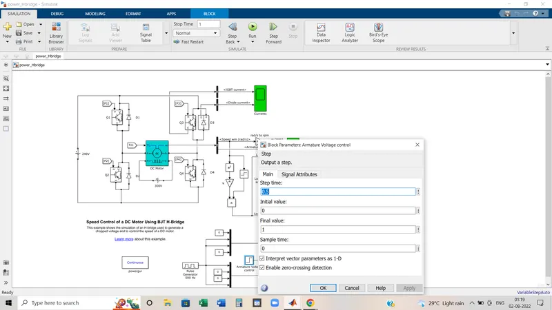
- Both states are occuring in 0.5 sec as step time is 0.5 sec.
- D1,D2,D3,D4 are the free-wheeling diodes.(Freewheeling diode is used to protect the circuit from unusual damage caused due to abrupt reduction in the current flowing through the circuit. It is also known as Flyback diode and forms connection across the inductor to remove Flyback voltage generated across it.)
Result:
Speed of motor:
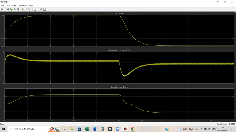
- From 0 to 0.5 sec the speed rises from 0 to nearly about 950 rpm (forward motoring region)
- Then Forward breaking mode is applied.
- Next 0.5 sec to 1 sec graph lags to 950 rpm at the negative side(Reverse motoring region)
- Next Reverse braking mode will be ON.
Load Torque of motor:
- From 0 to 0.5 sec the Torque rises from 0 to nearly about 6 Nm (forward motoring action)
- Then Forward breaking mode is applied.
- Next 0.5 sec to 1 sec graph lags to -6 Nm(Reverse motoring action)
- Next Reverse braking mode will be ON.
(1.B)
In the above scope result, the second graph shows the armature current changes. We can see there a sudden spike happens during the first switching condition and later after 0.5 sec when the transition is happening. During the transition, the motor is rotating in the reverse direction. As mentioned earlier, in reverse direction motor goes into generating mode.
- This spike is transient. When the motor starts it takes more current than its rated current.
- But we can change the spike or shoot-up values by changing the duty cycle.
- How much we will less the duty cycle value, the magnitude of transient current will be lesser.
- It means how frequently we change the switching condition of the motor, the transient value will be decreased.
Above model is based on the 75% duty cycle.
Now the duty cycle is 50% and the result is:
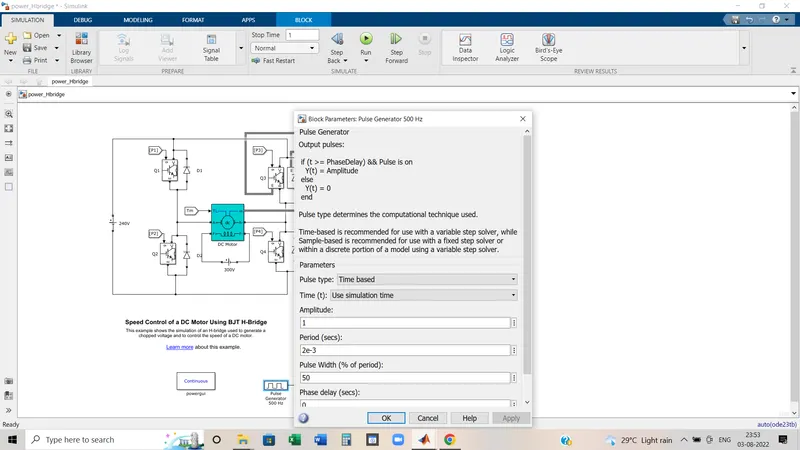
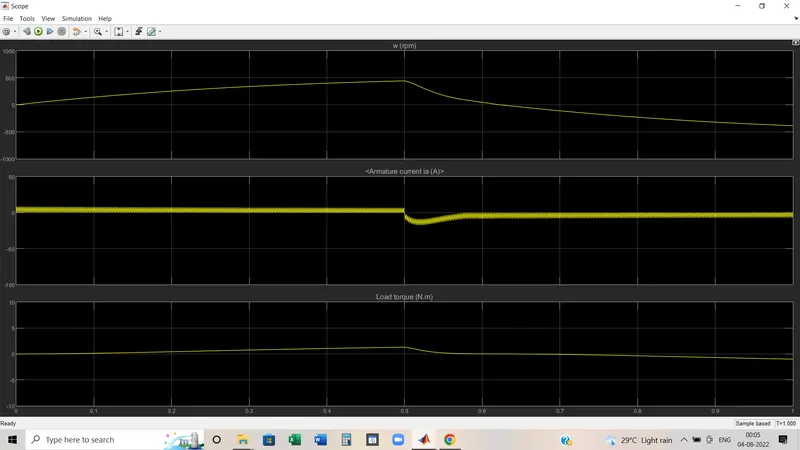
Here speed, Load torque has decreased than before.
And the transient current magnitude also has decreased. In the starting it close to zero.
Now duty cycle value is 25% and the result is :
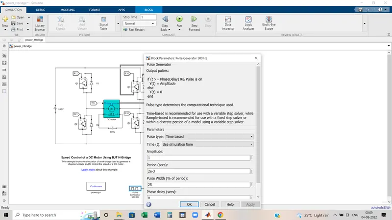
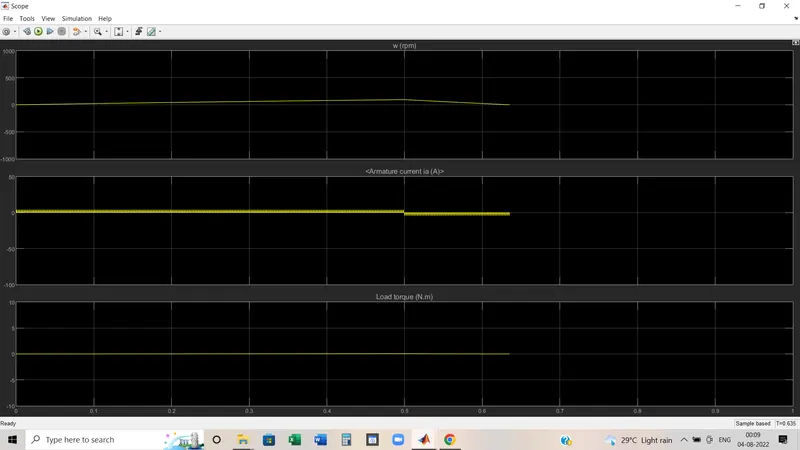
Here the spike of armature current has vanished.
So we can conclude that
In the H-Bridge circuit speed is controlled by changing the duty cycle. How much we put the lesser duty cycle, armature current will flow lesser and the speed of motor will be low. In the last condition where duty cycle value is 25%, there the speed is not enough to produce sufficient torque.
(1.C)
Simulink model and specification:
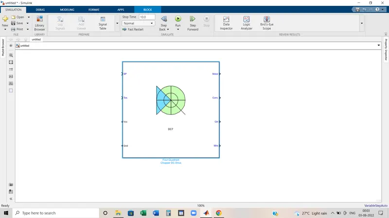
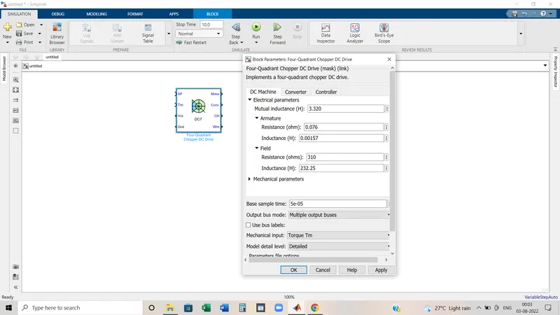
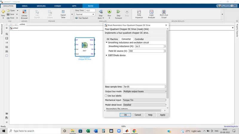
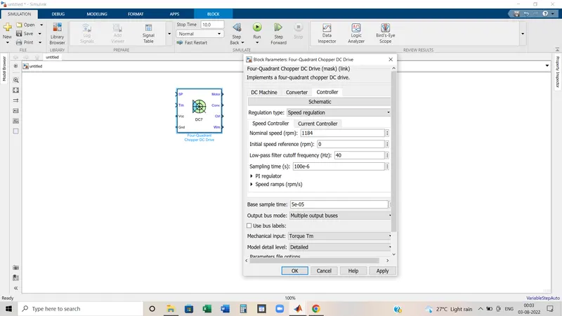
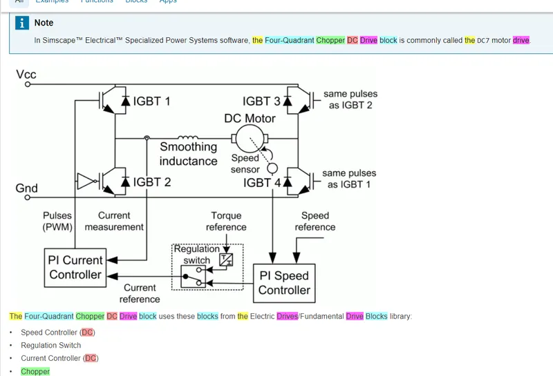
Connection diagram:
Description:
The Four-Quadrant Chopper DC Drive (DC7) block represents a four-quadrant, DC-supplied, chopper (or DC-DC PWM converter) drive for DC motors. This drive features closed-loop speed control with four-quadrant operation. The speed control loop outputs the reference armature current of the machine. Using a PI current controller, the chopper duty cycle corresponding to the commanded armature current is derived. This duty cycle is then compared with a sawtooth carrier signal to obtain the required PWM signals for the chopper.
The main advantage of this drive, compared with other DC drives, is that it can operate in all four quadrants (forward motoring, reverse regeneration, reverse motoring, and forward regeneration). In addition, due to the use of high switching frequency DC-DC converters, a lower armature current ripple (compared with thyristor-based DC drives) is obtained. However, four switching devices are required, which increases thecomplexity of the drive system.
Comparison:
- In Four quadrant Chopper DC drive, speed is controlled by the varying current in PI current controller but in the H bridge circuit speed is controlled by varying the duty cycle voltage.
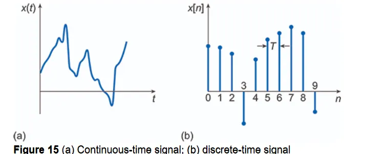
- DC7 has discrete time signal but H-Bridge has continuous time signal.
- Regenerative braking is not possible in H-Bridge circuit whereas in DC7 regenerative braking is possible.
- Efficiency is far better in the case of a four-quadrant DC chopper circuit.
- The main advantage of this drive, compared with other DC drives, is that it can operate in all four quadrants (forward motoring, reverse regeneration, reverse motoring, and forward regeneration). But H-bridge circuit works in 2 quadrant, Forward motoring and forward braking mode.
- DC7 is mainly used for Electric Vehicle but H bridge circuit employs in robotics technology.
(2)
What is chopper circuit: n electronics, a chopper circuit is any of numerous types of electronic switching devices and circuits used in power control and signal applications. A chopper is a device that converts fixed DC input to a variable DC output voltage directly.
The DC motor is used in many industrial applications requiring variable speed and load characteristics due to its ease of control. A chopper drive-based speed control is widely preferred as far as speed control is concerned. Choppers are mostly applied in electric cars, conversion of wind and solar energy, and DC motor regulators.
Different types of Chopper:
The main element based on which choppers are categorized is the semiconductor used in the chopper circuit. Based on the positioning of this semiconductor, choppers can be made to work in any of the four quadrant conditions. Depending on the quadrant of operation choppers are categorized as Type A, B, C, D, and E
- Type A chopper works in the first quadrant. In this chopper, the voltage and current both are positive and flows in the same direction. Power from source to load and the average output voltage is less than input DC voltage.
- Type B chopper works in the second quadrant. Here the load voltage is positive and current is negative. Power flows from load to source. This chopper is also known as a step-up chopper.
- Type C chopper is formed by parallel connection of Type A and Type B choppers.
- Type D chopper is the two quadrant type B chopper and Type E chopper is the fourth gradient chopper.
Two Quadrant Chopper:
Two Quadrant chopper is two types. These are
1.Two Quadrant type-A or type-C chopper:
In this types of Chopper Circuits, Type-A and Type-B are connected in parallel as shown in figure 3(a). Due to the presence of freewheeling diode FD across the load, the output voltage (Vo) is always positive. When the chopper CH2 is turned ON, the freewheeling diode FD conducts and thus obtaining the output voltage, vo=0. Similarly, When the chopper CH1 is turned ON, the diode D1 conducts and the output voltage is given by vo=Vs.
The current io flows in the arrow direction as shown in figure 3(a). Note that the load current can however be in reversed condition. So, we can say that the load current is positive when the chopper CH1 is at ON condition and freewheeling diodes conducts. And, the load current is negative if the chopper CH2 is at OFF condition or when D2 conducts. In other words, chopper CH1 and freewheeling diode FD operate as Type-A choppers in the first quadrant, and similarly, chopper CH2 and D2 operate together as Type-B in the second quadrant.
The average load voltage is always positive but the average load current may be either positive or negative as discussed above. Therefore, power flow may be from the source to load (first-quadrant operation) and from load to a source (second-quadrant operation).
Note that the chopper CH1 and CH2 should not be operated or turned ON at the same time as this would lead to a direct short circuit on the supply lines. This type of chopper is basically used for monitoring and regenerative braking of a DC motor.
2.Two Quadrant type-B or type-D chopper:
The power circuit diagram of Two-quadrant type-b or Type-D Chopper is shown in figure 4(a). When both the chopper CH1 and CH2 are at ON condition then the output average voltage vo=Vs. When both the chopper is turned OFF but diodes D1 and D2 conduct, then the output voltage vo=-Vs. The average output voltage is positive when the chopper turn-on time (Ton) is more than their turned-off (Toff) time i.e., Ton>Toff. Similarly, the average output voltage will be negative when the chopper turn-on time (Ton) is less than their turned-off (Toff) time i.e., Ton<Toff.
The direction of the flow of load current will always remain positive because chopper and diodes can conduct only in the direction as shown in figure 4(a). As the output voltage Vo is reversible, therefore the power flow is also reversible.
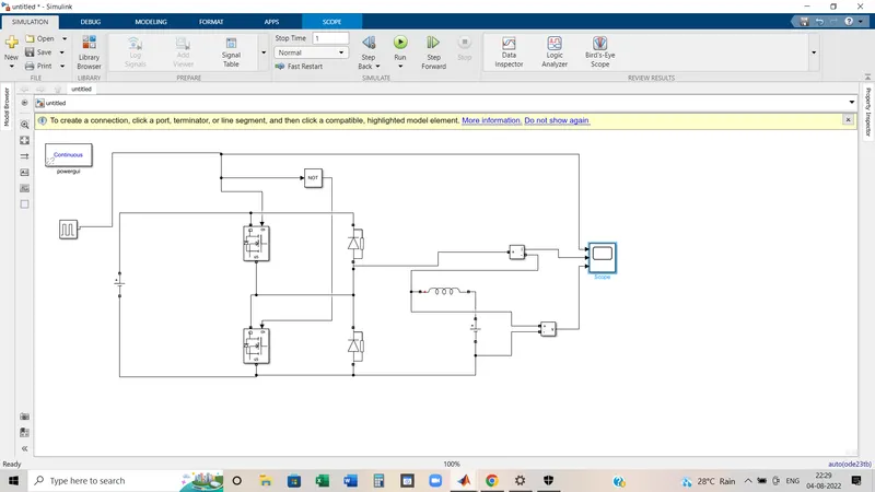
Simulink Model:
Simulink Model Description:
- Blocks Taken: MOSFET, Diode, Pulse Generator, Logical Operator(NOT Gate), Series RLC Branch(Later converted into Inductance), Voltage measurement, Current measurement, DC Voltage Source, Scope, and Powergui.
- as per the two quadrant chopper circuit, MOSFET switches and diodes are connected in series.
- DC voltage source is connected parallelly to supply the voltage.
- NOT gate is used to operate the switch non-simultaneously. Because if it operates simultaneously, supply can be short-circuited.
- That's why it has been tapped from one side and connected to the first MOSFET gate terminal and then from another side of NOT gate, the connection came to the Gate terminal of the 2nd MOSFET. as when the first switch is ON then another switch could remain in OFF position.
- An Inductor and voltage source has been used as the load terminal and across the load voltage measurement block has been connected.
Result:
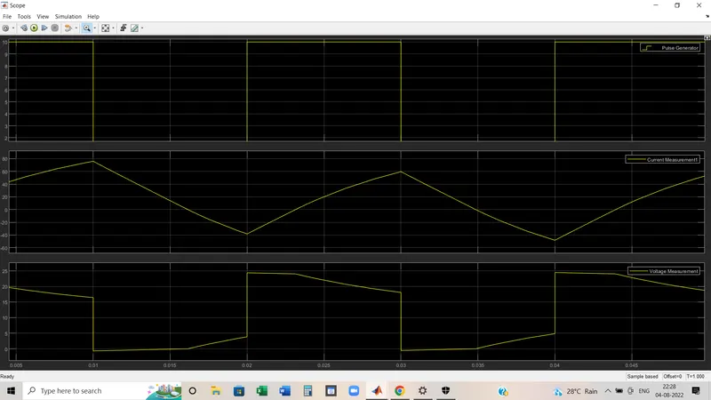
- First graph shows the input from the pulse generator which is being operated in 50% duty cycle.
- Second graph shows the current and it rises in a positive direction during ON state and goes down to negative side during OFF state.
- Third graph shows Voltage always remains in positive direction.
(3)
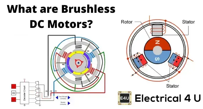
A brushless DC motor (also known as a BLDC motor or BL motor) is an electronically commuted DC motor that does not have brushes. The controller provides pulses of current to the motor windings which control the speed and torque of the synchronous motor.
These types of motors are highly efficient in producing a large amount of torque over a vast speed range. In brushless motors, permanent magnets rotate around a fixed armature and overcome the problem of connecting current to the armature. Commutation with electronics has a large scope of capabilities and flexibility. They are known for smooth operation and holding torque when stationary.
Working principle:
The operating principle of the BLDC motor is the same as that of the DC motor. Conductors facing a particular magnet pole (say N pole) carry current in one direction while those facing the other pole carry current in opposite direction. By virtue of this, the fields created by the magnet and armature conductors are always orthogonal to each other as shown in Fig. Note the naming convention “direct axis” and “quadrature axis”.
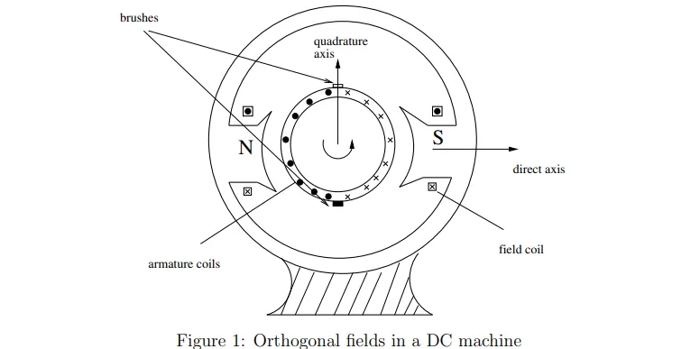
Suppose a two pole rotor is rotating under an armature. When N pole passes completely across a conductor, some mechanism is necessary to change the direction of current in that conductor. Otherwise direction of force on the conductor will be reversed (why?). In a conventional DC motor, the number of commutator segments equals the number of conductors in the armature. When a commuatator segment switches from one brush to the other, there is a change in supply direction (in case of motor). In BLDC machine, this reversal of direction of current is done via power electronic switches. Now, the instant of reversing the direction is a function of position of rotor. Hence, sensing of position is required which is “fedback” to the power electronics drive which “drives and controls” the supply given to the motor.
Working of BLDC Motor:
Before explaining the working of a brushless DC motor, it is better to understand the function of a brushed motor. In brush motors, there are permanent magnets on the outside and a spinning armature that contains an electromagnet is inside. These electromagnets create a magnetic field in the armature when the power is switched on and help to rotate the armature.
The brushes change the polarity of the pole to keep the rotation of the armature. The basic working principle for the brushed DC motor and for the brushless DC motor is the same i.e. internal shaft position feedback.
A Brushless DC motor has only two basic parts: the rotor and the stator. The rotor is the rotating part and has rotor magnets whereas the stator is the stationary part and contains stator windings. In BLDC permanent magnets are attached to the rotor and move the electromagnets to the stator. The high-power transistors are used to activate electromagnets for the shaft turns. The controller performs power distribution by using a solid-state circuit.
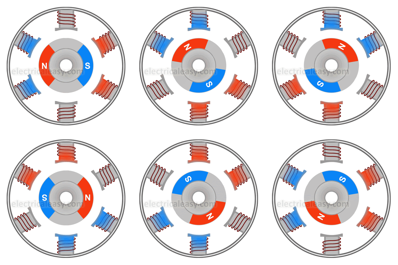
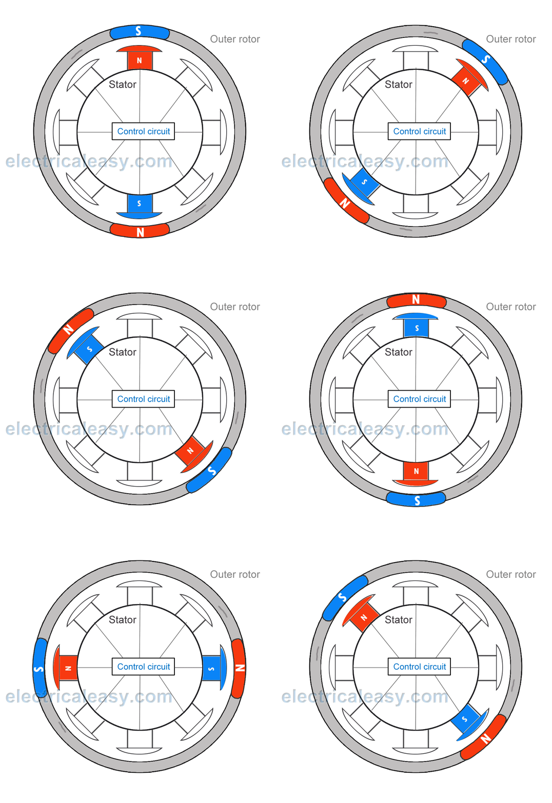
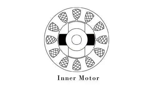
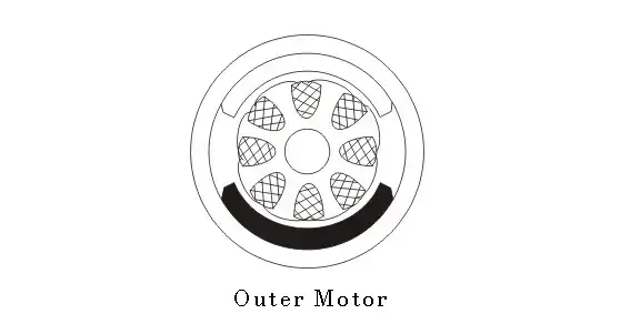
inner rotor design outer rotor design
Types of BLDC Motor:
Basically, BLDC is of two types, one is an outer rotor motor and the other is inner rotor motor. The basic difference between the two is only in design, their working principles are the same.
- Inner Rotor Design: In an inner rotor design, the rotor is located in the centre of the motor and the stator winding surround the rotor. As the rotor is located in the core, rotor magnets do not insulate heat inside and heat get dissipated easily. Due to this reason, inner rotor designed motor produces a large amount of torque and validly used.
- Outer Rotor Design: In outer rotor design, the rotor surrounds the winding which is located in the core of the motor. The magnets in the rotor trap the heat of the motor inside and do not allow to dissipate from the motor. Such type of designed motor operates at lower rated current and has low cogging torque.
Application:
BLDC motors fulfill many requirements that a brushed DC motor does. But as they require a complicated control circuit and due to cost considerations, they haven’t yet completely replaced brushed DC motors, especially in low-cost applications. Despite this, there are many applications where BLDC motors dominate –
- Consumer electronics – computer hard drives, small cooling fans, cd/dvd players, etc. and also in modern appliances where quiet operation is desired – such as washing machines, air conditioners, etc.
- Electric Vehicles – many electric vehicles including electric and hybrid cars, electric bikes use BLDC motors.
- They have a wide range of applications in many other areas including robotics, industrial, motion control systems, etc.