Week -2
1)
- Doorbell Theory:
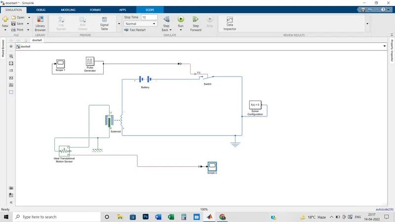
The heart of a doorbell is an Electromagnet.
Electromagnets are coils of wire(Solenoid) wrapped around a small piece of magnetic metal. When electricity passes through the wire, it creates a magnetic field around the wire.
When we press a doorbell button, then we actually complete an electrical circuit that allows electricity to flow through the doorbell's internal electromagnet or more specifically through the wire wrapped around a small piece of magnetic metal. Oersted’s Law states that when a steady electric current is passed through a metallic conductor, it creates a magnetic field around it. So according to the law, the magnetic material magnetize while a current flows through the wire. Then this magnetic material which is magnetized pulls the metal piston towards it and then the piston hits the tone bar that creates the doorbell sound.
As long we hold the doorbell button, current passes through the wire which leads to the continuation of the flow of current and magnetization remains. For that piston remains in the hitting position.
A solenoid is just a coil of wire, but when we run a current through it, we create an electromagnet.
Blocks Used:
- Battery: The instrumented variants have an extra physical signal port that outputs the internal state of charge. Use this functionality to change load behavior as a function of the state of charge, without the complexity of building a charge state estimator. Here nominal voltage = 12 V & internal resistance= 2 ohm.
- Switch: The Switch block models a switch controlled by an external physical signal. If the external physical signal PS is greater than the value specified in the Threshold parameter, then the switch is closed, otherwise, the switch is open.
Electrical switches add discontinuities to your model, and therefore your choice of the solver can influence the model behavior. - Electrical Reference: The Electrical Reference block represents an electrical ground. Electrical conserving ports of all the blocks that are directly connected to the ground must be connected to an Electrical Reference block. A model with electrical elements must contain at least one Electrical Reference block.
- Solenoid: It is an electromagnetic device.To show the direction in which the solenoid acts, the block icon changes dynamically based on the value of the Motion direction under the excitation parameter
- Ideal translational motion sensor: It is a device that converts an across variable measured between two mechanical translational nodes into a control signal proportional to velocity and position. The sensor is ideal since it does not account for inertia, friction, delays, energy consumption, and so on. Connections R and C are mechanical translational conserving ports and connections V and P are physical signal output ports for velocity and position, respectively.
- Mechanical translational reference: It is a frame or ground. Use it to connect mechanical translational ports that are rigidly affixed to the frame (ground)
- Solver configuration: Each physical network represented by a connected Simscape™ block diagram requires solver settings information for simulation. The Solver Configuration block specifies the solver parameters that your model needs before you can begin the simulation.
- Pulse generator: The Pulse Generator block generates square wave pulses at regular intervals. The block waveform parameters, Amplitude, Pulse Width, Period, and Phase delay, determine the shape of the output waveform. The following diagram shows how each parameter affects the waveform.
- Simulink-PS converter: To convert from a Mathematical-equation signal to a physical model.
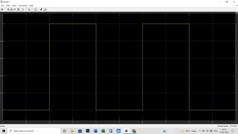
- Scope 1: To show the graph from the Pulse generator.
- PS-Simulink Converter: To convert from physical model to mathematical equation-based signal.
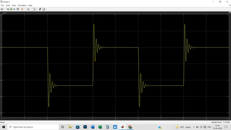
- Scope 2: To show the graph of the Ideal translational motion sensor.
Block Diagram:
Graph of Scope 1:
(Based on the Pulse Generator output) Reference values of Pulse generator are the following:
Amplitude = 1
Period= 4 sec
Pulse width percentage= 50
Phase delay= 2 sec
Graph of Scope 2:
(Based on the Ideal translational motion sensor)
2)
Used Blocks:
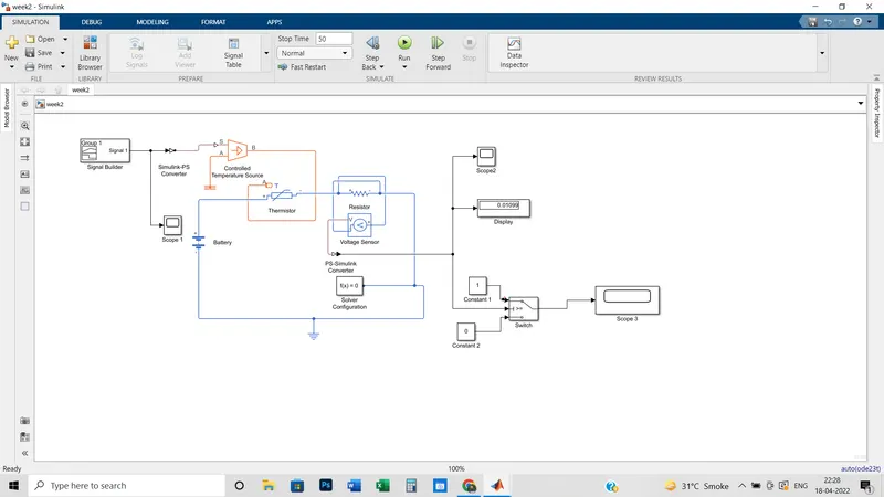
iii) Controlled Temperature Source: This block represents an ideal energy source in a thermal network that can maintain a controlled temperature difference regardless of the heat flow rate. The temperature difference is set by the physical signal port S. A positive temperature difference causes the temperature at port B to be greater than the temperature at port A
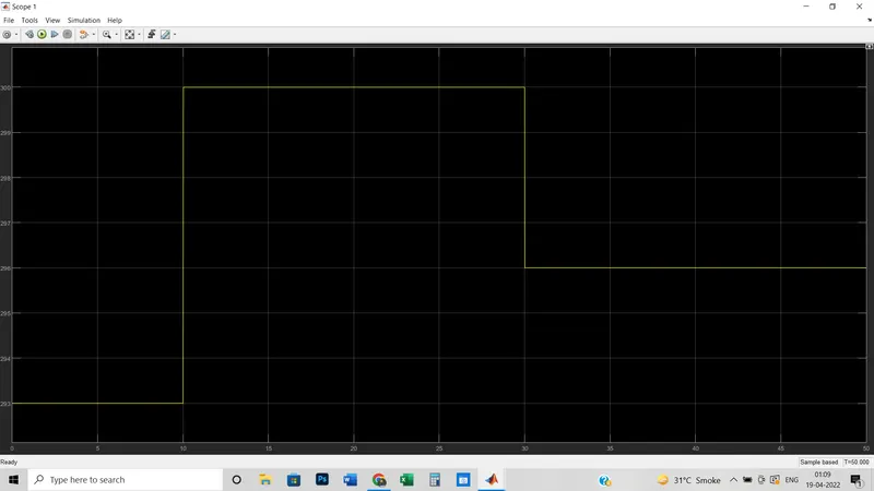
iv) Scope 1: It is used to show the input graph which is set in the Signal Builder block. By this scope block, the same graphical representation has been shown.
v) Battery: Battery is a storage device that provides the required voltage based on the parameter given.
vi)Thermistor: The word Thermistor is a combination of two words, Thermal and Resistor. A Thermistor is a type of resistor which is dependent on the temperature more than on the standard resistor. The Thermistor block represents the negative thermal co-efficient using the B parameter equation.
vii) Resistor: It is put in series with a thermistor to determine the threshold voltage.
viii)Voltage sensor: it is to sense the voltage magnitude across the resistor.
ix) Solver Configuration: It is mandatory to put in the physical circuit to transform into the mathematical equation.
x)PS-Simulink configuration: It is added to transform the physical signal into the Simulink signal.
xi) Display: It is the value we have to put in the threshold voltage section in the switch.
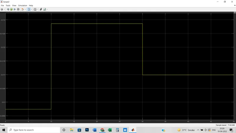
xii) Scope 2: It is nothing but the graph according to the display coming to the output from the voltage sensor connected across the resistor.
xiii) Switch: The Switch block passes through the first input or the third input signal based on the value of the second input. The first and third inputs are data inputs. The second input is a control input. Specify the condition under which the block passes the first input by using the Criteria for passing the first input and Threshold parameters. Here we have to also set the temperature value of 298 Kelvin or 25 degree centigrade at output minimum and maximum value under the signal attribute section of the Switch block.
Here port 2 is for control input signal and ports 1 & 3 are for the input signal.
Here we have to add the threshold voltage value as per the display block. 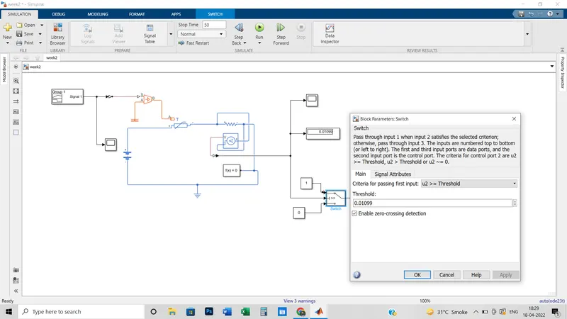
xiv) Constant 1: It is nothing but the value put in the switch to determine the output graph.
xv) Constant 2: It is nothing but the value put in the switch to determine the output graph same as the constant.
xvi) Scope 3: It is for the output graph to see the on & off conditions of the thermistor.
xvii) Electrical reference: It is mandatory to connect with any electrical physical circuit.
xviii) Thermal reference: It is mandatory to connect with any thermal physical circuit.
Block Diagram:
Output Graph:
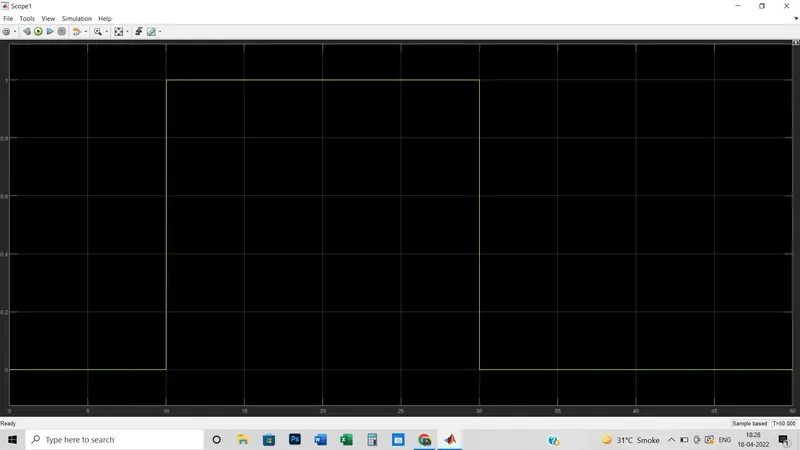
(As per the Scope 3 block)
From this graph, we can conclude that From 0 to 10 seconds, Thyristor is in off condition.
Then 10 to 30 seconds Thyristor is in on position as here the temperature is 27 degree centigrade and at and more than 25 degree centigrade Thyristor should be in on position. After that i.e. from 30 to 50 seconds, it remains in the off position again because during this time period temperature is 23-degree centigrade.