Project 1 Mechanical design of battery pack
Objective: Preparation of a detailed battery pack drawing along with its enclosure.
Assumption: Battery pack voltage: 72 Volt
Given: Battery pack capacity: 18 kWh
Consider: Cell: ANR26650M1-B
From the manufacturer's datasheet:
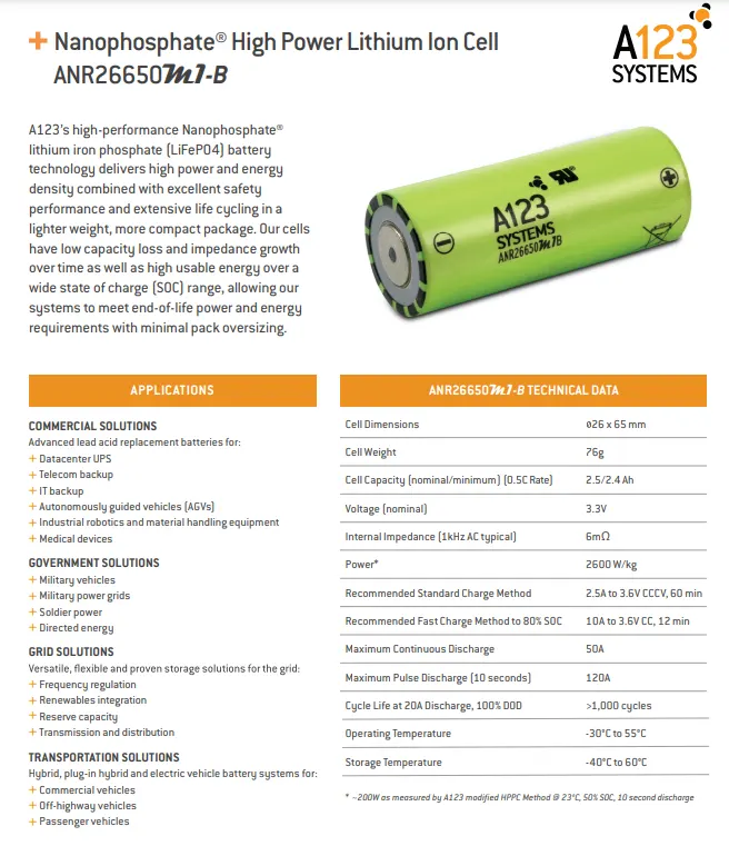
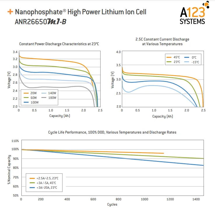
Here is the manufacturer: A123_system.
Detailed analysis of datasheet:
- Cell dimensions: 26 x 65 mm which refers to the diameter of the cell 26 mm and the cell length is 65 mm.
- Cell weight: 76 gm.
- Cell Capacity: 2.5 Ah
- Nominal Voltage: 3.3 Volt
- Internal Impedance (1kHz AC typical) : 6mΩ
- Power : 2600 W/kg
- Recommended Standard Charge Method: 2.5A to 3.6V CCCV, 60 min
- Recommended Fast Charge Method to 80% SOC: 10A to 3.6V CC, 12 min
- Maximum Continuous Discharge: 50A
- Maximum Pulse Discharge (10 seconds): 120A
- Cycle Life at 20A Discharge, 100% DOD: >1,000 cycles
- Operating Temperature: -30°C to 55°C
- Storage Temperature: -40°C to 60°C
Calculation:
- Given data: Battery capacity(Energy) = 18 kWh( which means the battery can deliver 18 kW if it runs for one hour or 9 kW if it runs for 2 hours)
= 18000 watt-hour
- Assume, Battery pack voltage = 72 Volt
- So the Capacity of battery pack (in Ah) = (18000/72) = 250 Ah. (It means the battery can supply 250 A constantly for 1 hour or 125 A for 2 hours or 83.3 A for 3 hours).
- Now coming to the series and parallel combination of cells to make the 18 kWh battery pack.
As we know the voltage of the battery pack increases when we increase the number of cells in series and if we increase the parallel string connection then it boosts the battery pack capacity.
Cells in series :
cell voltage= 3.3 volt
battery pack voltage= 72 volt
so the number of cells in series= 72/3.3 = 21.8 =near to 22
String in parallel :
Cell ampere capacity= 2.5 Ah
Battery pack capacity= 250 Ah
Total parallel connenction= (250/2.5) = 100
So the connection will be 22s100p.
Total number of cells= 22 x 100= 2200
- Battery pack volume,
One cell radius = 26/2 = 13 mm = 0.013 m
one cell length= 65 mm = 0.065 m
one cell volume = π*r^2*h = 3.1415 * (0.013)^2 * 0.065 = 0.0000345 m^3 = 0.0345 mm^3 = 0.0345 Ltr
Total battery pack volume = 2200*0.0345 = 75.99 Ltr
- Battery pack mass,
One cell mass= 76 g
Battery pack mass= 76 * 2200 = 167200 g = 167.2 Kg.
- Energy Density of Battery Pack,
Battery pack mass= 167.2 Kg
Energy of battery pack= 18 kWh= 18000 watt-hour
Energy density= (18000/167.2) = 107.65 Wh/Kg
Battery Pack Construction:
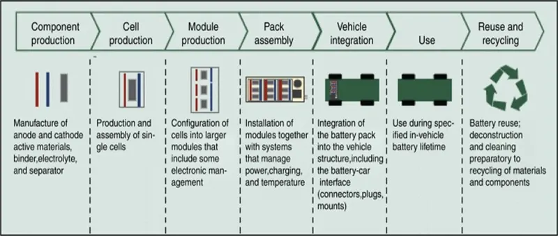
This is a typical diagram from the cell to the battery pack and its recycling.
Here the discussion will be from the cell-to-pack assembly.
To construct a battery pack, the following materials are needed.
1. LiFePO4 cell (3.6 V, 2.4 Ah) : 220 pieces
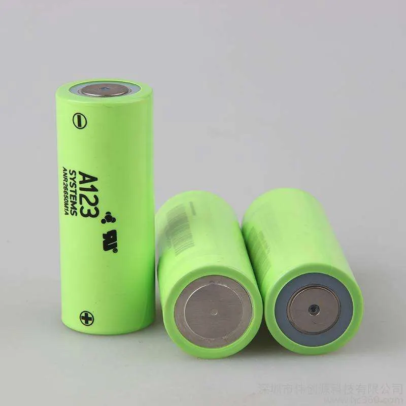
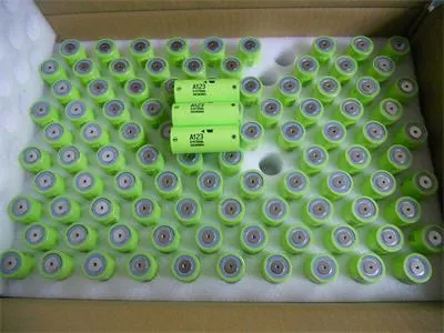
The lithium iron phosphate battery (abbreviated as Li-IP, LFP (lithium Ferro-phosphate) or LiFePO4 battery) is a type of lithium-ion battery using lithium iron phosphate (LiFePO4) as the cathode material and a graphitic carbon electrode with a metallic backing as the anode. The energy density of an LFP battery is lower than that of other common lithium-ion battery types such as nickel manganese cobalt (NMC) and nickel cobalt aluminum (NCA), and also has a lower operating voltage.
Of their lower cost, high safety, low toxicity, long cycle life, and other factors, LFP batteries are finding a number of roles in-vehicle use.
2. Battery pack holder :
Along with giving you an easy framework to build complete battery packs, using 18650 cell holders provide several advantages:
- Cell holders provide critical spacing between the cells. This allows for much better cooling characteristics as compared to cells that are in direct contact with each other.
- Using cell holders makes your battery pack more solid.
- Cell holders give your battery pack an element of vibration resistance.
- For these reasons, we recommend always using 18650 cell holders when building a battery pack.
3. H-type Nickel Strip:
- Solid nickel strips with a thickness of 0.015 inches can carry about 1 amp of current per millimeter of width.
- For series connections, simply cut small nickel strips to fit between Parallel groups.
- It's always good to leave around 10mm of strip for connecting the BMS sense wires.
4. 22s 72 V Battery Management System :
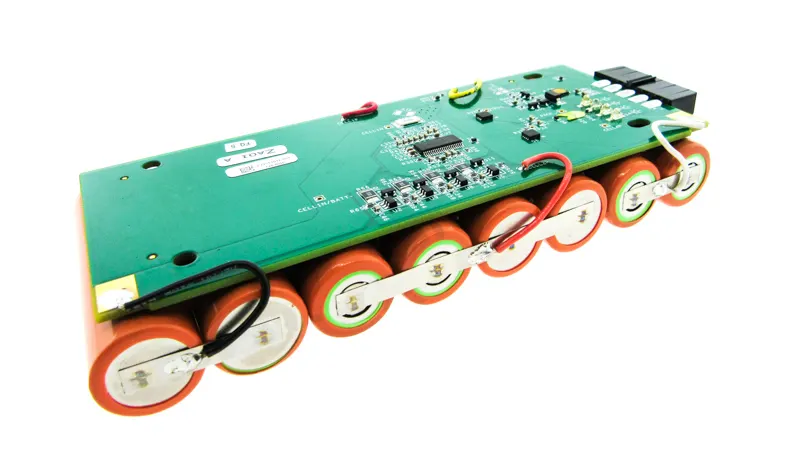
While your battery is now technically ready to use, I wouldn’t recommend it. Remember, if you don’t have any form of over-current or over-charge protection, a battery can be dangerous. If something goes wrong with your battery, load, charger, or even a wire, you could be in for some serious trouble.
- This is why a BMS is essential. A BMS, or Battery Management System, is a small circuit board that converts several dangerous, fairly useless lithium-ion cells into one safe, useful, battery pack.
- Overcharge Protection: A BMS Monitors the voltage of all cell groups. When any one of those cell groups reaches 4.2V, charging is stopped. This prevents your cells from being damaged from being overcharged and also helps prevent fires.
- Cell Balancing: If one or more of your cell groups are at a higher voltage than the others, a BMS uses a circuit and small balance resistors to lower the voltage of any high cells.
- Over-Discharge Protection: A BMS disables the battery pack when any cell's voltage falls below a certain threshold. This threshold is usually 2.5 to 3.0 volts. Remember, if a cell goes much lower than that, it will get damaged.
- Over-Current Protection: Another critical job of a BMS is to make sure the battery pack is not put under too much stress. So, every BMS has a maximum current that, if achieved, will turn the battery pack off. Over-current protection applies to both charging and discharging the battery pack.
- Short Circuit Protection: A short circuit is equivalent to a 0 Ohm load. Ohm’s law states that the amount of current that will flow through a given circuit is a function of, among other things, the circuit’s resistance and voltage. When a short circuit condition is created, the only resistance to the flow of current will be the very low resistance of the conductor (wire or nickel) and the cell itself.
- Making the connection of BMS: a BMS cable will have 1 black wire on the end. This goes to the main battery negative and is known as the B0 connection. Then, the very next wire in the cable will go to where the first cell’s positive end is connected to the second cell’s negative connection. This is known as the B1 connection, and so on.
Simply solder each sense wire where it goes on the battery pack and the BMS will be able to read, change, or completely disable the battery pack power in the event of an emergency condition.
The very last step is getting the power out of the BMS. Remember, we ran the main battery positive directly to the battery connector and the main battery negative into the BMS using the B- connection. So, to get the power out of the BMS, we are going to need to locate the P- connection. Luckily, that is usually clearly marked on most BMS boards.
Solder a wire from the P- to the negative side of your DC connector and you should be good to go. Keep in mind that some BMS boards do not send any voltage out until they see a charge on the input. So, if you built your very first battery pack and you are seeing 0V on the output, don't panic! Just put it on a charger for a moment to activate the BMS.
5. PVC heat shrink tube:

Heat shrink tubing, also known as heat shrink, is a shrinkable tube that shrinks radially when exposed to heat. Produced using a two-step process, heat shrink is available in a wide range of materials to suit almost any application.
- The main advantage is its ability to withstand high temperatures up to 125°C–135°C. PVC-based heat shrink tubes offer brighter and more vibrant colors and better clarity if a clear tube is needed. PVC is also available in flame-retardant versions and has better tensile strength and abrasion resistance than polyolefin materials.
6. Spot welding machine:
- When it comes to how to connect 18650 cells together, there are many different methods. In high-end industrial settings, it's not uncommon to find batteries that are laser welded, ultrasonically welded, or even robotically welded.
- When it comes to building a lithium-ion battery pack in the consumer space, however, there are two methods: Soldering or Spot Welding.
- Generally speaking, spot welding will always be the best choice compared to soldering. There are, however, some exceptions to this rule that we will explore a bit later. The problem with spot welding a battery pack is that a good spot welder typically costs substantially more than a soldering iron of equivalent quality.
- Spot Welding: Spot welding is the most common method used to build a 18650 battery pack. This is because spot welding enables the cells to be joined together without adding a lot of heat. Also, each spot weld takes far less time than an equivalent soldered connection would.
- Soldering: If you have no other way to put a battery together, then soldering a lithium-ion battery would be a good choice. The main problem with soldering is that you must apply a large amount of heat to the cell to form a bond. That heat does not dissipate quickly.
Conclusion:
Here the whole process has been discussed on how we can build an 18 kWh battery pack. In the case of the higher larger battery pack, some more materials can be added like a cell fuse or thermal management system could be different to minimize the heat energy. Otherwise, all materials will be the same as the above.
In the case of a series-parallel connection, depending on the voltage and capacity requirement, cell quantity in series or parallel will be varied.
Ref: