Project
(IN CASE OF OPEN LOOP)
BLOCKS:
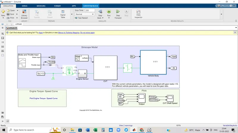
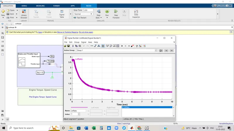
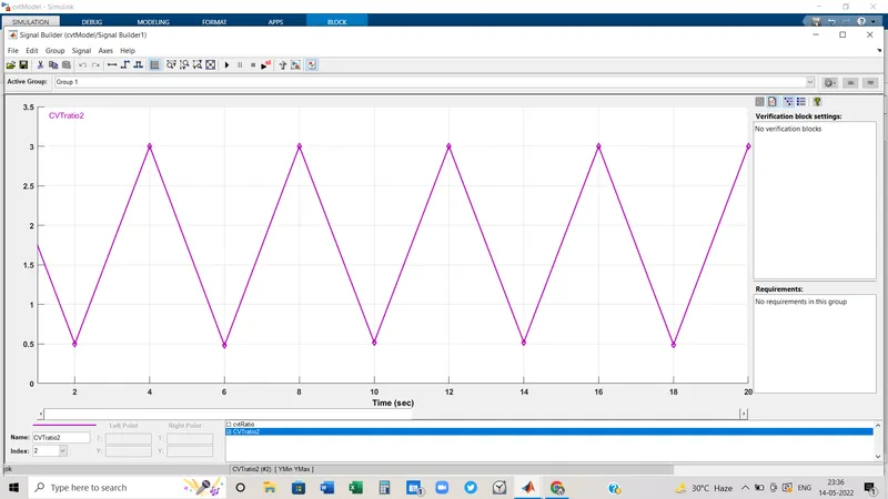
- Signal Builder: The Signal Builder block allows you to create interchangeable groups of piecewise linear signal sources and use them in a model. You can quickly switch the signal groups into and out of a model to facilitate testing. In the Signal Builder window, create signals and define the output waveforms. To open the window, double-click the block.
- Generic Engine: The Generic Engine block represents a general internal combustion engine. Engine types include spark-ignition and diesel. Speed-power and speed-torque parameterizations are provided. A throttle physical signal input specifies the normalized engine torque. Optional dynamic parameters include crankshaft inertia and response time lag. A physical signal port outputs engine fuel consumption rate based on the choice of fuel consumption model. Optional speed and redline controllers prevent the engine to stall and enable cruise control.
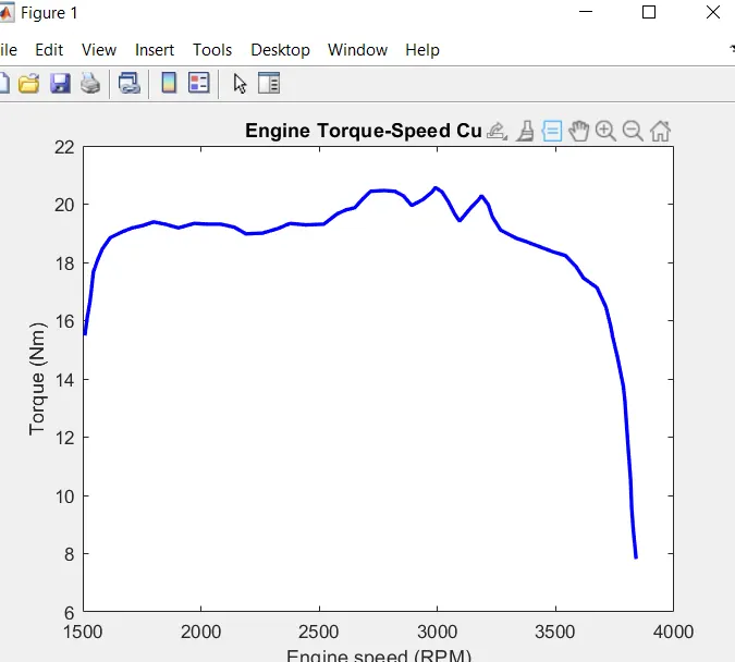
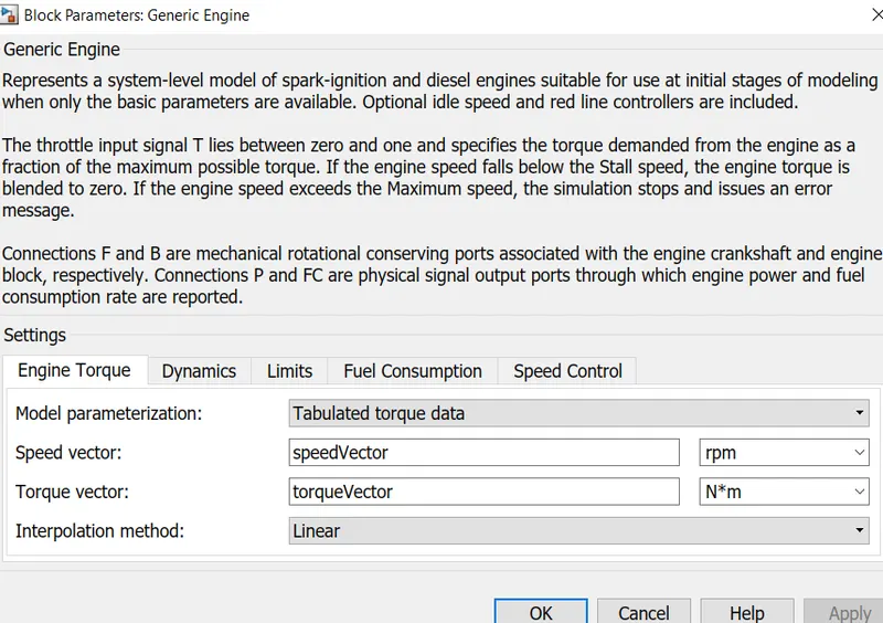 we used Torque and speed data which is required to run the generic engine from the Torque-speed curve. By using Grabit we can extract all the data points in the datasheet and from there, we feed those values into the requisite parameter section of the generic engine. As per the following graph, we can see the points which have been fed into the generic engine.
 -
- Simple Gear: The Simple Gear block represents a gearbox that constrains the connected driveline axes of the base gear, B, and the follower gear, F, to corotate with a fixed ratio that you specify. You choose whether the follower axis rotates in the same or opposite direction as the base axis. If they rotate in the same direction, the angular velocity of the follower, ωF, and the angular velocity of the base, ωB, have the same sign. If they rotate in opposite directions, ωF and ωB have opposite signs.
- Solver Configuration: The Mechanical Rotational Reference block represents a reference point, or frame, for all mechanical rotational ports. All rotational ports that are rigidly clamped to the frame (ground) must be connected to a Mechanical Rotational Reference block.
- Mechanical Rotational Reference: The Mechanical Rotational Reference block represents a reference point, or frame, for all mechanical rotational ports. All rotational ports that are rigidly clamped to the frame (ground) must be connected to a Mechanical Rotational Reference block.
- Simulink-PS Converter: The Simulink-PS Converter block converts the input Simulink® signal into a physical signal. Use this block to connect Simulink sources or other Simulink blocks to the inputs of a Physical Network diagram.
To convey signal conversion while taking up minimal canvas space, the block icon changes dynamically based on whether it is connected to other blocks.
- Display: The Display block shows the value of the input data. You can specify the frequency of the display. For numeric input data, you can also specify the format of the display. If the block input is an array, you can resize the block vertically or horizontally to show more than just the first element. If the block input is a vector, the block sequentially adds display fields from left to right and top to bottom. The block displays as many values as possible. A black triangle indicates that the block is not displaying all input array elements.
- From: The From block accepts a signal from a corresponding Goto block, then passes it as output. The data type of the output is the same as that of the input from the Goto block. From and Goto blocks allow you to pass a signal from one block to another without actually connecting them. To associate a Goto block with a From block, enter the Goto block's tag in the Goto Tag parameter.
A From block can receive its signal from only one Goto block, although a Goto block can pass its signal to more than one From block. - Goto: The Goto block passes its input to its corresponding From blocks. The input can be a real- or complex-valued signal or vector of any data type. From and Goto blocks allow you to pass a signal from one block to another without actually connecting them. A Goto block can pass its input signal to more than one From block, although a From block can receive a signal from only one Goto block. The input to that Goto block is passed to the From blocks associated with it as though the blocks were physically connected. Goto blocks and From blocks are matched by the use of Goto tags.
- Sub-system: As a model increases in size and complexity, you can simplify it by grouping blocks into subsystems. A subsystem is a set of blocks that you group into a single Subsystem block.
Using subsystems:
-
Establishes a hierarchical block diagram, where a Subsystem block is on one layer and the blocks that make up the subsystem are on another.
-
Keeps functionally related blocks together.
-
Helps reduce the number of blocks displayed in your model window.
-
Establishes an interface with inputs and outputs.
When you make a copy of a subsystem, that copy is independent of the source subsystem. To reuse the contents of a subsystem across a model or across models, consider referenced subsystems, referenced models, or subsystems linked to a block in a custom library. A subsystem can be virtual or nonvirtual. A virtual subsystem provides a graphical hierarchy in a model and does not impact the execution of a model. A nonvirtual subsystem executes as a single unit within a model.
In this model 3(Three) subsystem has been used.
- Engine Sensor:
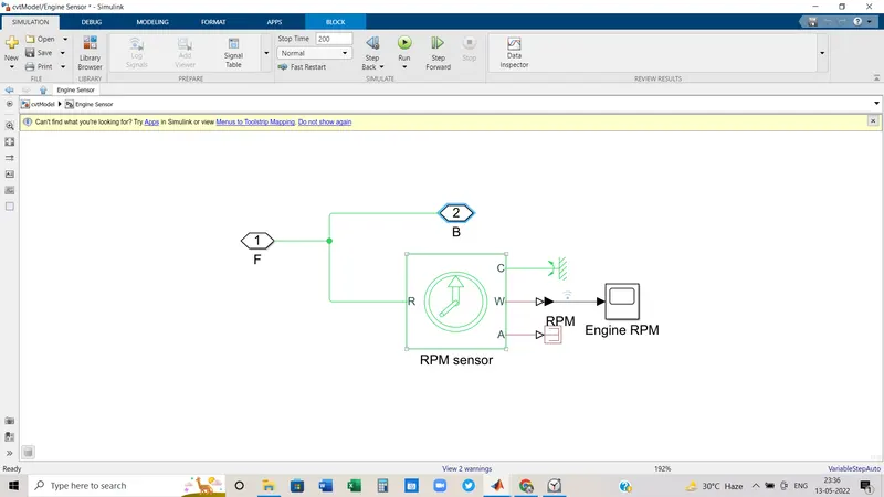
Here F & B are Physical modelling blocks. Engine sensor is collaborated by RPM sensor, Display block, PS terminator, PS-rotational reference block and PS-Simulink converter block.
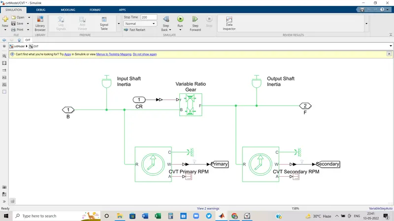
- CVT(Continuous Variable Transmission): It consists mainly primary pulley, variator, secondary pulley, and belt. Variator is connected with primary pulley and secondary pulley. When the radius of primary pulley is less than the radius of secondary pulley, and the primary pulley is inward and the secondary pulley moves outward, that leads to speed reduction. and in the opposite scenario, overdrive happens. In simscape we use a variable gear ratio block to reduce speed and make overdrive. To sense the RPM we use the RPM sensors which are in bottom side of the picture.
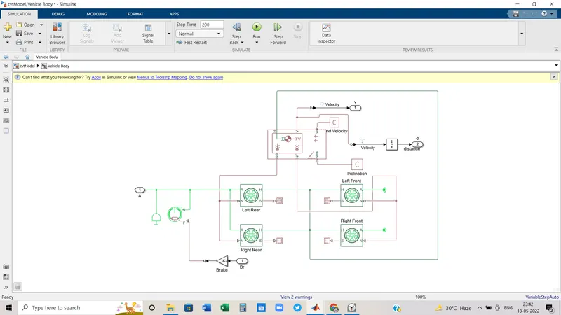
- Vehicle Body: Though various blocks are connected in this subsystem but mainly consist of vehicle body block and wheels. 4 wheels have been used here.
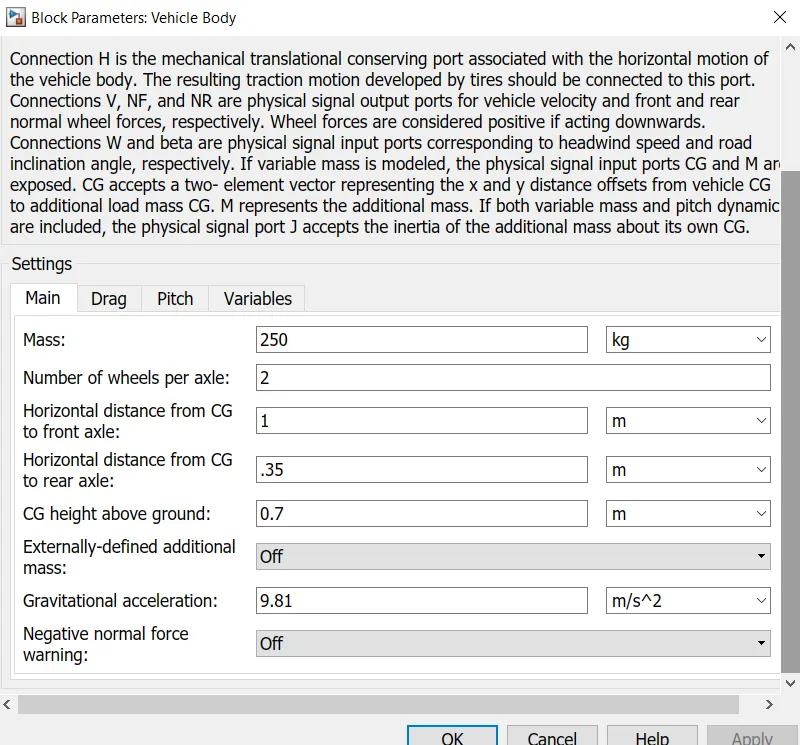
 Here are the vehicle body block parameters that are taken as default values. we can change those according to the requirement.
INPUT:
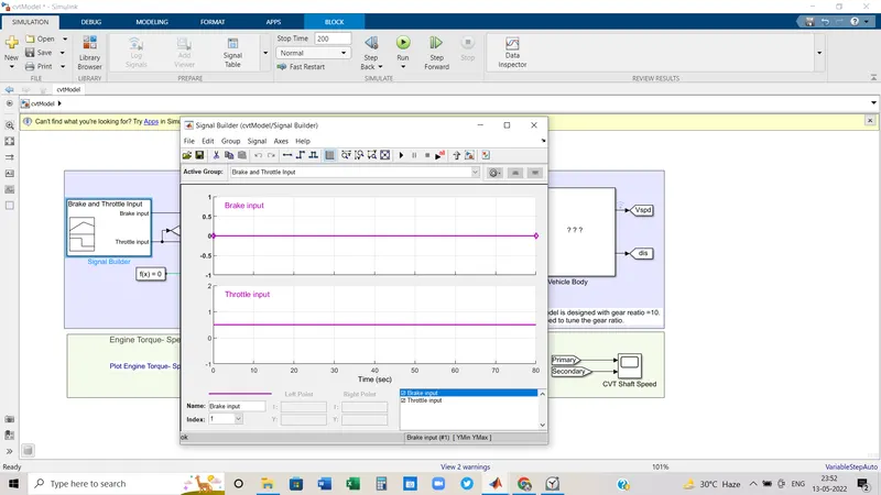
- Brake Input : We have taken the value as 0(zero) with time.
- throttle input: Throttles are not used in diesel engines, but the term throttle can be used to refer to any input that modulates the power output of a vehicle's prime mover. Throttle response is often confused with increased power but is more accurately described as time rate of change of power levels.
Here the Throttle input we have taken is 0.5
RESULT:
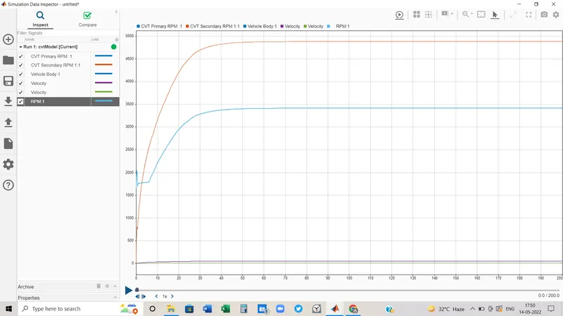
From the data inspector section, we can compare all the values in one graph.
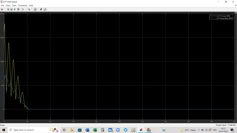
- CVT Primary RPM value is less than the CVT secondary RPM value, which will lead to overspeed.
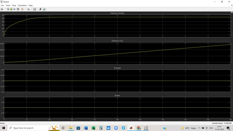
- The velocity lies between 50 to 60 kmph.
- The distance covered by the vehicle is about 3000 km.
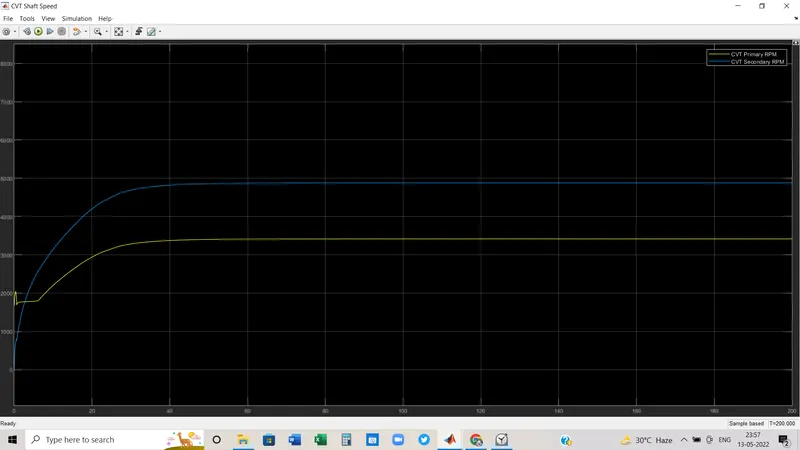
This is nothing but the primary CVT RPM and secondary CVT RPM in duration of 200 sec and we can see here.
Important Result:
If we change the gear ratio by a pulse signal, we can see the change in the graph of CVT primary RPM and CVT secondary RPM. While gear ratio is moving towards 0.5 value the primary is decreasing and secondary RPM is increasing accordingly.
(IN CASE OF CLOSED-LOOP)
Though we performed an open-loop CVT system it's not realistic because the CVT ratio is dependent on a vehicle velocity.
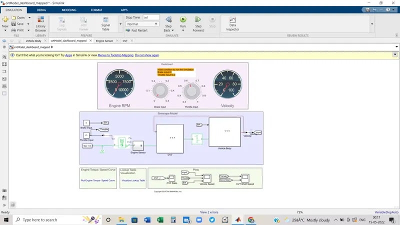
Here in this block diagram, from the output section of the velocity body is feeding to CVT subsystem.
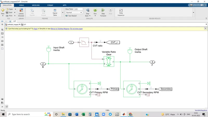
inside the CVT subsystem, we used a lookup table.
- Lookup Table: A lookup table is an array of data that maps input values to output values, thereby approximating a mathematical function. Given a set of input values, a lookup operation retrieves the corresponding output values from the table. It means while CVT ratio is depending on output velocity, we feed velocity to a look-up table as input, and depending on that new values of CVT ratio will be produced.
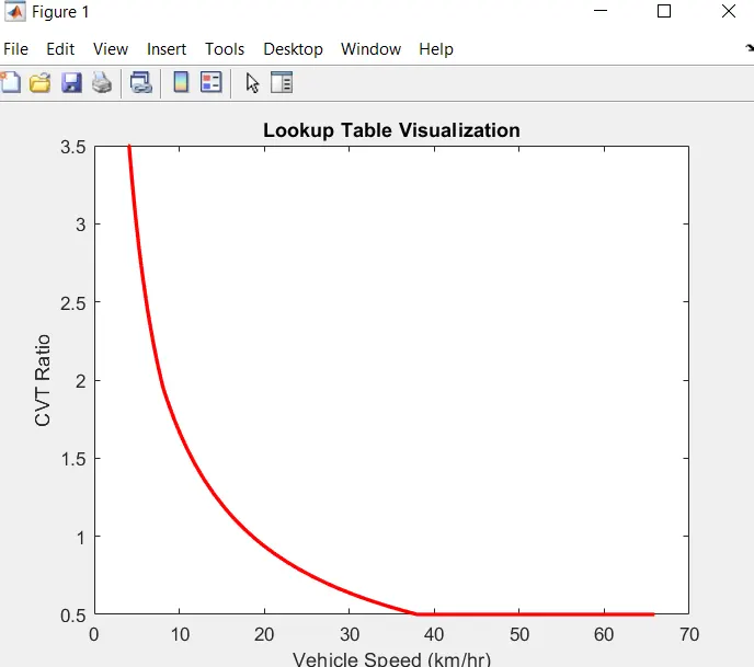
In above picture: how CVT ratio has changed with changing velocity.
RESULT:
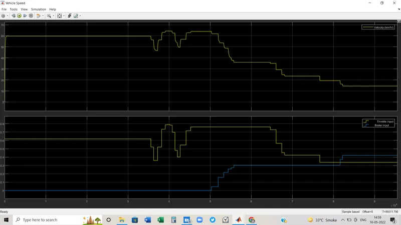
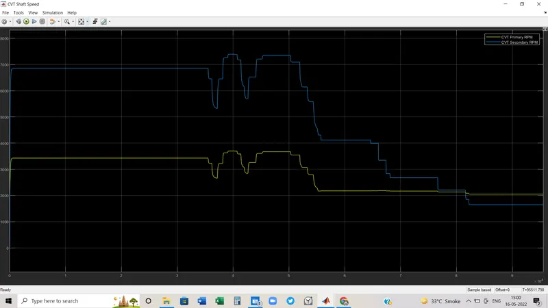
In closed-loop system simulation time, we took infinitely and for a certain period, varied the throttle input and brake input as per the graph, and depending on that velocity has also changed or varied. Depending on velocity, CVT primary RPM and CVT secondary RPM varied(in the 2nd graph).
CONCLUSION:
We took two block diagrams where in the first case CVT was without a lookup table and in the second case like a practical scenario, a lookup table consists inside the CVT subsystem.
By the above diagrams and analysis, we can design All_Terrain_Vehicle which can be used to run on various types of terrain.