Final Project: Design of an Electric Vehicle
Create a MATLAB model of an electric car which uses a battery and a DC motor. Choose suitable blocks from Powertrain block set. Prepare a report about your model including the following:
Objectives:
1. System-level configurations
2. Model parameters
3. Results
4. Conclusion
Project Details:
Theory:
What is an Electric Vehicle: An electric vehicle (EV) is one that operates on an electric motor, instead of an internal-combustion engine that generates power by burning a mix of fuel and gases. Therefore, such as a vehicle is seen as a possible replacement for current-generation automobiles, in order to address the issue of rising pollution, global warming, depleting natural resources, etc. Though the concept of electric vehicles has been around for a long time, it has drawn a considerable amount of interest in the past decade amid a rising carbon footprint and other environmental impacts of fuel-based vehicles.
How Electric Vehicle Works:
All-electric vehicles, also referred to as battery electric vehicles (BEVs), have an electric motor instead of an internal combustion engine. The vehicle uses a large traction battery pack to power the electric motor and must be plugged into a wall outlet or charging equipment, also called electric vehicle supply equipment (EVSE). Because it runs on electricity, the vehicle emits no exhaust from a tailpipe and does not contain the typical liquid fuel components, such as a fuel pump, fuel line, or fuel tank.
Electric cars function by plugging into a charge point and taking electricity from the grid. They store the electricity in rechargeable batteries that power an electric motor, which turns the wheels. Electric cars accelerate faster than vehicles with traditional fuel engines – so they feel lighter to drive.
Key components of Electric Vehicle:
- Battery (all-electric auxiliary): In an electric drive vehicle, the auxiliary battery provides electricity to power vehicle accessories.
- Charge port: The charge port allows the vehicle to connect to an external power supply in order to charge the traction battery pack.
- DC/DC converter: This device converts higher-voltage DC power from the traction battery pack to the lower-voltage DC power needed to run vehicle accessories and recharge the auxiliary battery.
- Electric traction motor: Using power from the traction battery pack, this motor drives the vehicle's wheels. Some vehicles use motor generators that perform both the drive and regeneration functions.
- Onboard charger: Takes the incoming AC electricity supplied via the charge port and converts it to DC power for charging the traction battery. It also communicates with the charging equipment and monitors battery characteristics such as voltage, current, temperature, and state of charge while charging the pack.
- Power electronics controller: This unit manages the flow of electrical energy delivered by the traction battery, controlling the speed of the electric traction motor and the torque it produces.
- Thermal system (cooling): This system maintains a proper operating temperature range of the engine, electric motor, power electronics, and other components.
- Traction battery pack: Stores electricity for use by the electric traction motor.
- Transmission (electric): The transmission transfers mechanical power from the electric traction motor to drive the wheels.
Block diagram of Electric Vehicle modeling:
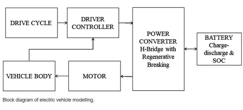
Drive Cycle: A drive cycle is typically represented by a series of data points that plots vehicle speed against time. Driving cycles are produced to assess the performance of vehicles in various ways, including fuel consumption and pollutant emissions.
Drive Controller: Motor Controllers and Drives are electrical or electronic devices that regulate motor speed, torque, and position outputs. The drive modifies the power input to the motor to achieve the desired output.
H-Bridge: Motor Controllers and Drives are electrical or electronic devices that regulate motor speed, torque, and position outputs. The drive modifies the power input to the motor to achieve the desired output.
Battery: An electric vehicle battery is a rechargeable battery used to power the electric motors of a battery electric vehicle or hybrid electric vehicle. Typically lithium-ion batteries, they are specifically designed for high electric charge capacity.
Motor: In an electric vehicle, when the driver applies the accelerator, the battery in the car supplies electricity to the stator, causing the rotor to turn, and subsequently provide mechanical energy to turn the car’s gears. Once the gears are rotating, the wheels turn too. All this happens in the blink of an eye, and without fossil fuel combustion!
Vehicle Body: The electric car's skeleton is called a space frame and is made of aluminum to be both strong and lightweight. The wheels are also made of aluminum instead of steel, again as a weight-saving method. The aluminum parts are poured at a foundry using specially designed molds unique to the manufacturer.
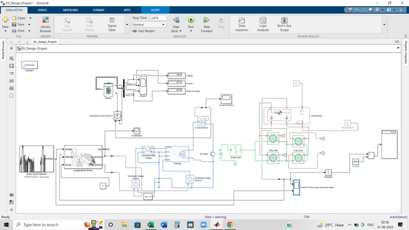
MATLAB-Simulink model of an Electric Vehicle:
Model Block Description:
1. Vehicle Body:
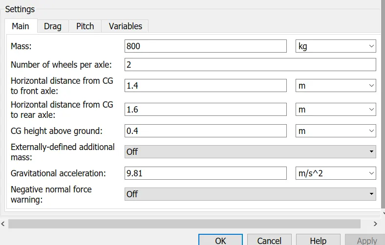
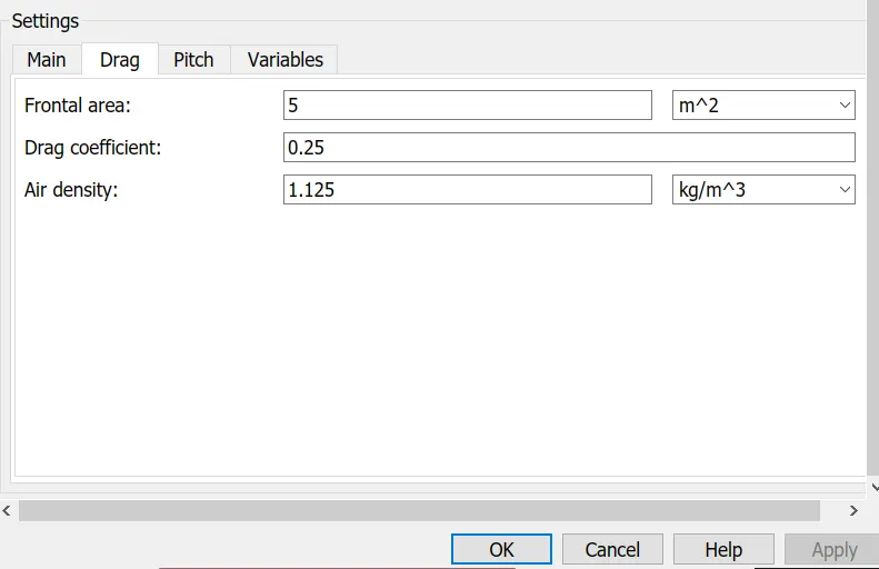
Represents a two-axle vehicle body in longitudinal motion. The block accounts for body mass, aerodynamic drag, road incline, and weight distribution between axles due to acceleration and road profile. The vehicle can have the same or a different number of wheels on each axle. Optionally include pitch and suspension dynamics or additional variable mass and inertia. The vehicle does not move vertically relative to the ground.
- H is the mechanical translational conserving port associated with the horizontal motion of the vehicle body. The resulting traction motion developed by tires should be connected to this port.
- V is the Feedback Velocity. It is a physical signal but as it is feedback velocity so sent back to the longitudinal driver block we need to change it to Simulink signal and it denotes the at which speed the vehicle is running.
- NF and NR are physical signal output ports for front and rear normal wheel forces, respectively.
- W and beta are physical signal input ports corresponding to headwind speed and road inclination angle, respectively.
2. Wheel:
Represents the longitudinal behavior of a highway tire characterized by the tire Magic Formula. The block is built from Tire-Road Interaction (Magic Formula) and Simscape Foundation Library Wheel and Axle blocks. Optionally, the effects of tire inertia, stiffness, and damping can be included.
Each tire has four ports:
- A is the mechanical rotational conserving port for the wheel axle.
- H is the mechanical translational conserving port for the wheel hub through which the thrust developed by the tire is applied to the vehicle.
- N is a physical signal input port that applies the normal force acting on the tire. The force is considered positive if it acts downwards.
- S is a physical signal output port that reports the tire slip.
- Optionally exposes physical signal port M by setting Parameterize to Physical signal Magic Formula coefficients. Physical signal port M accepts a four-element vector corresponding to the B, C, D, and E Magic Formula coefficients.
3. Simple Gear:
Represents a fixed-ratio gear or gearbox. No inertia or compliance is modeled in this block. You can optionally include gear meshing and viscous bearing losses.
Connections B (base) and F (follower) are mechanical rotational conserving ports. Specify the relation between base and follower rotation directions with the Output shaft rotates parameter. Optionally include thermal effects and expose thermal conserving port H by setting the Friction model to a temperature-dependent setting.
- For this application, The ratio is taken as 2.
- Output shaft rotation direction is taken: 'in same direction as input shaft.'
- Other parameters are kept unchanged.
4. DC Motor:
This block represents the electrical and torque characteristics of a DC motor.
The block assumes that no electromagnetic energy is lost, and hence the back-emf and torque constants have the same numerical value when in SI units. Motor parameters can either be specified directly, or derived from the no-load speed and stall torque. If no information is available on armature inductance, this parameter can be set to some small non-zero value.
When a positive current flows from the electrical + to - ports, a positive torque acts from the mechanical C to R ports. Motor torque direction can be changed by altering the sign of the back-emf or torque constants.
- Positive port: Electrical conserving port associated with the DC motor positive terminal.
- Negative port: Electrical conserving port associated with the DC motor negative terminal.
- C port: Mechanical rotational conserving port associated with the DC motor case. It is the casing part(stationary). It is connected with the mechanical rotational reference.
- R port: Mechanical rotational conserving port associated with the DC motor rotor. Here it is connected with the base port of Gear box.
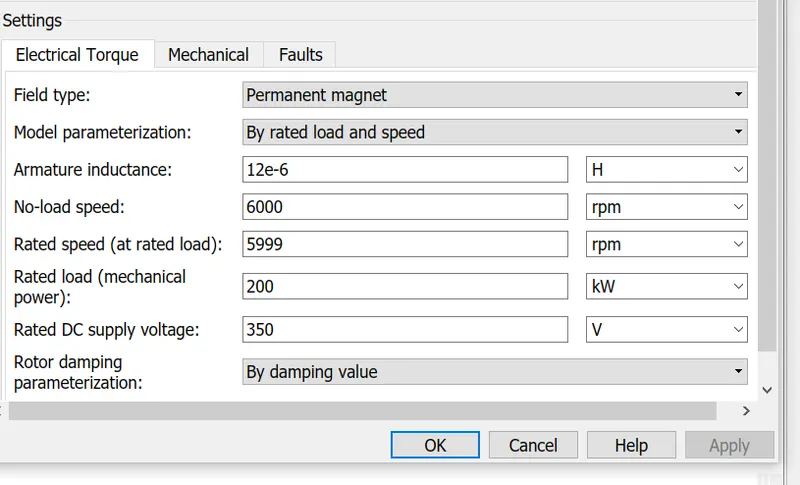
Mechanical and fault sections are kept default. Here No load speed is fixed to 6000 rpm and rated speed to 5999 rpm. The difference between no-load speed and rated speed decides how much speed the vehicle can achieve compared to the drive cycle input velocity.
5. H-Bridge Power converter:
This block represents an H-bridge motor drive. The block can be driven by the Controlled PWM Voltage block in PWM or Averaged mode. In PWM mode, the motor is powered if the PWM port voltage is above the Enable threshold voltage. In Averaged mode, the PWM port voltage divided by the PWM signal amplitude parameter defines the ratio of the on-time to the PWM period. Using this ratio and assumptions about the load, the block applies an average voltage to the load that achieves the correct average load current. The Simulation mode parameter value must be the same for the Controlled PWM Voltage and H-Bridge blocks.
If the REV port voltage is greater than the Reverse threshold voltage, then the output voltage polarity is reversed. If the BRK port voltage is greater than the Braking threshold voltage, then the output terminals are short-circuited via one bridge arm in series with the parallel combination of a second bridge arm and a freewheeling diode. Voltages at ports PWM, REV, and BRK are defined relative to the REF port.
The H-Bridge block output is a controlled voltage that depends on the input signal at the PWM port. If the input signal has a value greater than the Enable threshold voltage parameter value, the H-Bridge block output is on and has a value equal to the value of the Output voltage amplitude parameter. If it has a value less than the Enable threshold voltage parameter value, the block maintains the load circuit using one of the following three Freewheeling mode options:
-
Via one semiconductor switch and one freewheeling diode -
Via two freewheeling diodes -
Via two semiconductor switches and one freewheeling diode
(The first and third options are sometimes referred to as synchronous operation.)
The signal at the REV port determines the polarity of the output. If the value of the signal at the REV port is less than the value of the Reverse threshold voltage parameter, the output has positive polarity; otherwise, it has negative polarity.
- PWM_port: Electrical conserving port associated with the pulse-width modulated signal. The voltage is defined relative to the REF port.
- REF_port: Electrical conserving port associated with the floating zero volt reference.
- REV_port: Electrical conserving port associated with the voltage that controls when to reverse the polarity of the H-Bridge block output. The voltage is defined relative to the REF port.
- BRK_port: Electrical conserving port associated with the voltage that controls when to short circuit the H-Bridge block output. The voltage is defined relative to the REF port.
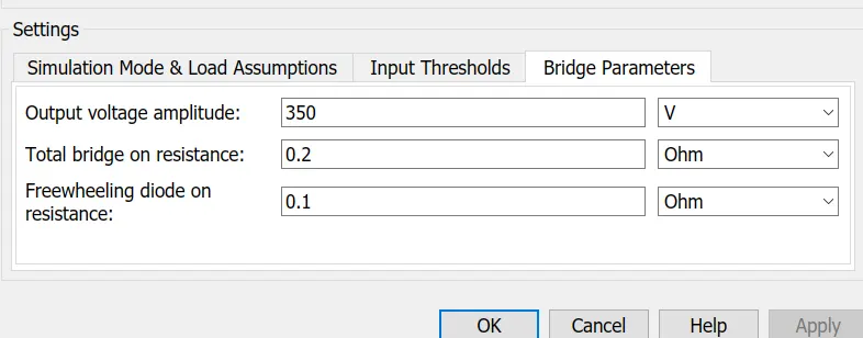
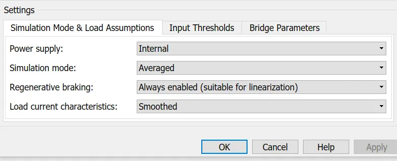
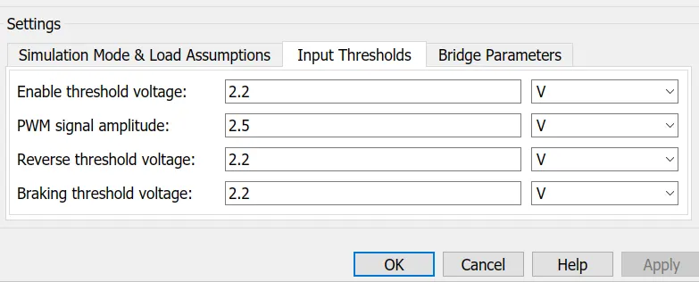
Here are the details of the parameter value to run the model as per requirement.
6. Controlled PWM Voltage:
This block creates a Pulse-Width Modulated (PWM) voltage across the PWM and REF ports. The output voltage is zero when the pulse is low, and is equal to the Output voltage amplitude parameter when high. Duty cycle is set by the input value. Right-click the block and select Simscape->Block choices to switch between electrical +ref/-ref ports and PS input u to specify the input value.
At time zero, the pulse is initialized as high unless the duty cycle is set to zero or the Pulse delay time is greater than zero.
The Simulation mode can be set to PWM or Averaged. In PWM mode, the output is a PWM signal. In Averaged mode, the output is constant with value equal to the averaged PWM signal.
-
Electrical input ports — The block calculates the duty cycle based on the reference voltage across its ref+ and ref- ports. This modeling variant is the default.
-
PS input — Specify the duty cycle value directly by using an input physical signal port.
- Ref(+) : It is positive electrical reference voltage and it enabled for the Electrical input ports variant of the block.
- Ref(-) : It is negative electrical reference voltage and it enabled for the Electrical input ports variant of the block.
- PWM_port : Electrical conserving port associated with the pulse-width modulated signal.
- Ref_port : Electrical conserving port associated with the floating zero volt reference.
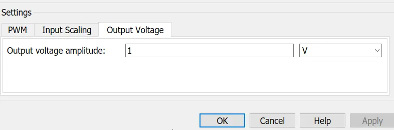
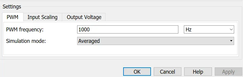
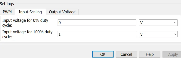
As the input signal is coming from Simulink block and Simulink blocks are only associated with two numbers 0,1 so at 0% duty cycle input voltage is 0 and input voltage for 100% duty cycle is 1. PWM frequency can be varied to feed different voltage level to the motor.
7. Controlled Voltage Signal:
The block represents an ideal voltage source that is powerful enough to maintain the specified voltage at its output regardless of the current passing through it. The output voltage is V = Vs, where Vs is the numerical value presented at the physical signal port.
8. Longitudinal driver:
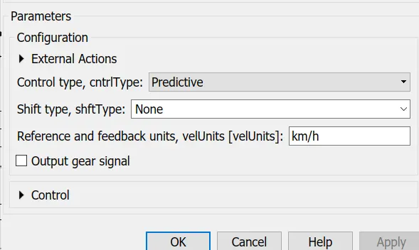
A parametric longitudinal speed tracking controller for generating normalized acceleration and braking commands based on reference and feedback velocities.
By using the external actions to input signals that can disable, hold, or override the closed-loop commands determined by the block. The block uses this priority for the input commands: disable, hold, override.
- Vel_ref : Reference velocity, vref, in m/s
- Vel_fdbk : Longitudinal vehicle velocity, U, in the vehicle-fixed frame, in m/s.
- Grade : Road grade angle, θ or γ, in deg.
- Accl_cmd : Commanded vehicle acceleration, yacc, normalized from 0 through 1.
- Decel_cmd : Commanded vehicle deceleration, ydec, normalized from 0 through 1.
9. Drive Cycle Source:
A driving cycle is a series of data points representing the speed of a vehicle versus time.
Here FTP75 drive cycle has been taken. FTP75 is the Federal Test Procedure. It is the standard one to test vehicles fuel consumption of dischrarge timing, milage and other parameters.
As per the requirement other cycles could be used.
10. Current sensor:
The block represents an ideal current sensor, that is, a device that converts current measured in any electrical branch into a physical signal proportional to the current.
- Connections + and - are conserving electrical ports through which the sensor is inserted into the circuit. Connection I is a physical signal port that outputs current value.
11. Battery:
The Battery block implements a generic dynamic model that represents most popular types of rechargeable batteries.
The circuit parameters can be modified to represent a specific battery type and its discharge characteristics. A typical discharge curve consists of three sections.
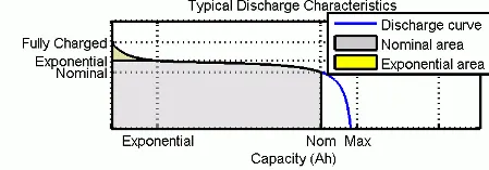
The first section represents the exponential voltage drop when the battery is charged. The width of the drop depends on the battery type. The second section represents the charge that can be extracted from the battery until the voltage drops below the battery nominal voltage. Finally, the third section represents the total discharge of the battery, when the voltage drops rapidly.
When the battery current is negative, the battery recharges, following a charge characteristic.
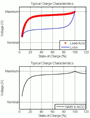
The model parameters are derived from the discharge characteristics. The discharging and charging characteristics are assumed to be the same.
The Exp(s) transfer function represents the hysteresis phenomenon for the lead-acid, nickel-cadmium (NiCD), and nickel-metal hydride (NiMH) batteries during the charge and discharge cycles. The exponential voltage increases when a battery is charging, regardless of the battery's state of charge. When the battery is discharging, the exponential voltage decreases immediately.
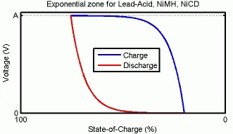
The state of charge (SOC) for a battery is a measure of battery's charge, expressed as a percent of the full charge. The depth of discharge (DOD) is the numerical compliment of the SOC, such that DOD = 100% - SOC.
For example, if the SOC is:
-
100% — The battery is fully charged and the DOD is 0%.
-
75% — The battery is 3/4 charged and the DOD is 25%.
-
50% — The battery is 1/2 charged and the DOD is 50%.
-
0% — The battery is has 0 charge and the DOD is 100%.
Connection:
- Port connection of Vehicle body along with tires and gearbox:
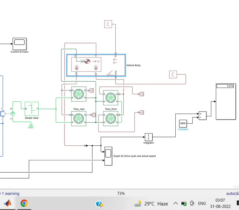
- The H (mechanical translational conserving port) port of each tire is connected with the H port of the vehicle body.
- NR is the Rear wheel force connected with the rear-wheel N port to develop force in the rear tires.
- Similar way, the NF port is connected with the front tires to develop force in the front wheel axis.
- Beta is connected with PS-constant block as it is considered to have zero degrees inclination angle of the road.
- Similarly W (Wind velocity is also considered a zero constant value and to evaluate it, the PS-constant block is connected there.
- V port in the vehicle body is for the feedback velocity so it is connected with the longitudinal driver block because as per the speed the vehicle is able to achieve compared t the drive cycle, the driver block will give the command to run the vehicle.
- A is simply connected with the other wheel on the same axis.
- The Axis of the rear wheel is affixed with an F(follower) port, also called the driver gear of a simple gear block.
- S(tire slip) of each tire is connected with the terminator block as it is not considered for this application.
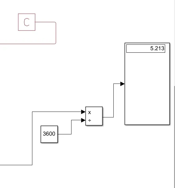
- To determine the distance covered by the vehicle an integration block has been used to convert it from speed to distance and to convert the distance unit to Km, the total no of seconds(3600 sec) in an hour is divided by using a constant block.
- Port connection of H-Bridge converter, controlled PWM voltage, Longitudinal driver, Drive cycle, and other related blocks:
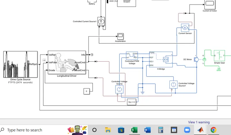
- After completing Vehicle body design, we need to add Motor. Here for simplicity, DC motor has been taken. C port refers to the casing or stationary part so to hold it a reference is conneceted and R goes to the base of driving port of gear box.
- Green part of the motor denotes to mechanical and blue is denoting electrical part.
- Ammeter or current sensor always connects in series so from the positive side of H-bridge goes to positive port of current sensor and other(-ve) side comes to motor positive port.
- As here DC motor is taken so H-bridge motor drive is best for it. in case of BLDC or Induction motor we should take other drives. For BLDC motor ESC(Electronic Speed Control) drive is recommended and for Induction motor various drives such as Rotor resistance drives or variable voltage variable frequency drives are used as per the application.
- To control the input voltage Controlled PWM voltage is used. Here from PWM port a physical signal goes to the PWM port of H-Bridge drive.
- Negative ports or reference ports are recommended to connect with grounding block because of balancing the current.
- Now coming to the acceleration and deceleration port of Longitudinal drive which works during the throttle and braking period.
- First for acceleration, from AccelCmd port, a signal is feeding to controlled voltage source and the +ve port of the same goes to controlled PWM voltage. It is for controlling the voltage during acceleration period.
- In case of deceleration, same port connection has been initiated but here the simulink signal is coming from DeclCmnd port and by changing to physical signal goes to Braking port of the drve through a similar voltage controlled source. By using this port during deceleration battery gets charged and SOC increases.
- A solver is connected to solve all physical mathematical equations.
- Drive cycle output is feeding to Longitudinal driver hub at VelRef port.
- At the VelFdbk port the actual speed is coming to determine the driver the next step compared to the input drive cycle.
- Here Grade(road gradient or angle) is considered 0.
- Port connections of Battery and related blocks:
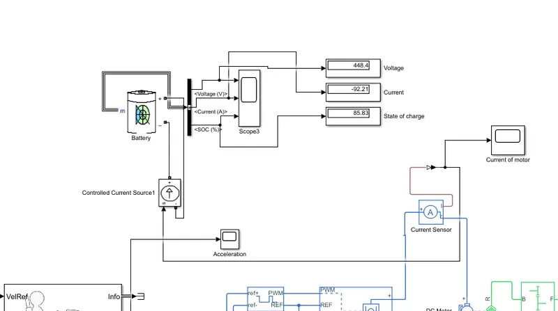
- From special power system liabrary Battery is taken. Various battery sources are available in simscape liabrary but this battery has its own SOC, current and voltage signal output to see the result so we do not need to create signals to see the output result.
- Through controlled current source, simulink signal has been sent to the drive. To change the signal Simulink-PS converter is used.
- A current sensor is to measure the current and it sends the current to the electrical branch.
Results and clarifications:
- Distance covered by the vehicle in 2474 sec: 5.2 km.
-
- After 2474 sec the voltage of battery, current and state of charge percentage:
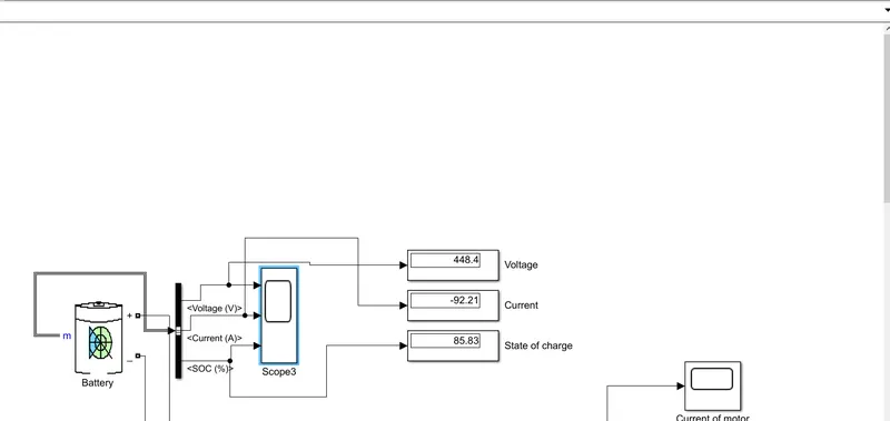
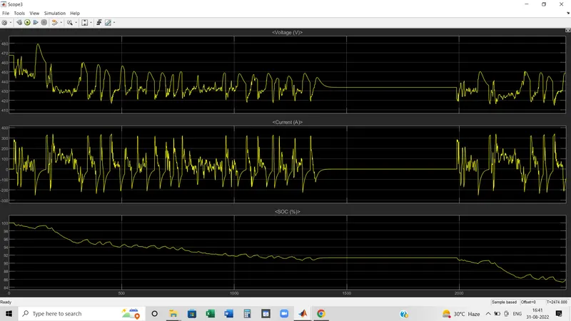
The graph is showing the voltage, cureent and SOC percentage status in running condition of vehicle.
In SOC percentage section, we can see that during deceleration period, the SOC percentage bit increaded and during acceleration period battery looses charges. During standstill condition charge remained same.
Same way, voltage and current requirement is high during acceleration period and decreases during deceleration period.
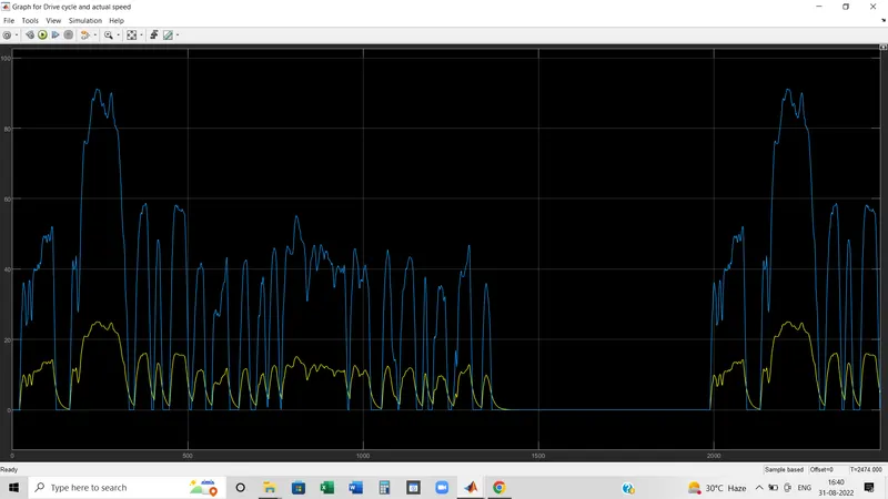
This graph shows though the input drive cycle amplitude of velocity quite higher but in practical vehicle could not achieve that much of higher amplitude. So to achieve that, motor or other parameters(such as voltage requirement etc) should be changed accordingly.
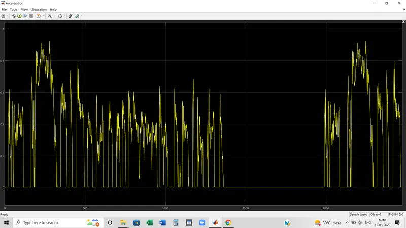
The graph shows the change of acceleration with respect to time.
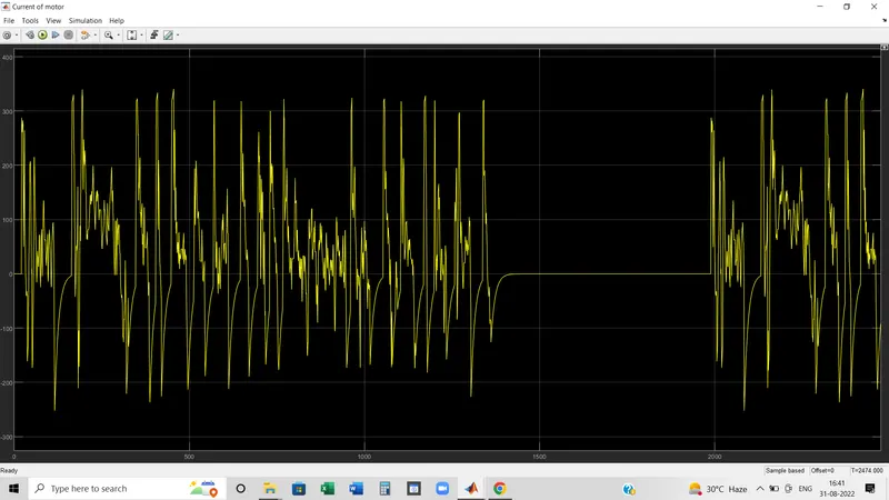
This graph shows the current taken by the motor.
NOTE: The MATLAB file has been attached(Google drive link: https://drive.google.com/file/d/1reTIC2_8ZQTYlMvV7P9uULGtjYljW3oc/view?usp=sharing )
--------------------------------------------------------------