Project 1 (Mini Project on Vehicle Direction Detection
SITUATION
The objective of the project is to create a Simulink model for the Vehicle direction detection application for the automobile.
TASK
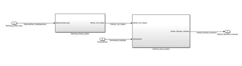
- The two inputs are Camera and steering wheel direction which are fed into the system.
- Camera reads the road signs & stores into its memory with unique values for left turn, right turn & straight drive.
- Depending on the direction it is taking, final indication is given to the driver – as an indication if he is driving in the recommended direction or not.
ASSESSMENT
Requirement - 1.
- In the subsytem 1 the steering wheel is fed as an input and this value is compared against the default three angular values of the steering wheel from which the direction of the wheel is specified.
- The specified direction of the wheel is fed as an output with a signal name Vehicle_Turn_Status.
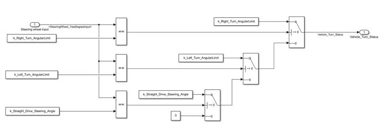
The subsystem consist of three stages. i) The input value from the steering wheel which is compared against the default angular values using the relational operator and the boolean value is obtained as an output.
ii) The switch pass the input1 when the input2 condition gets satisfied orelse the input 3 pass to the output. The not equal to zero is condition set to the switch blocks. The predefined angular values pass as the Vehicle turn status signal. If none of the condition gets satisfied the zero becomes the output.
iii) The vehicle turn status signal is fed to the outport.
Requirement - 2.
- In the subsytem 2 the vehicle turn status is fed as an input and this value is compared against the calibrated angular values of the steering wheel.
- The three signal are compared against the camera input signal to get the Vehicle_Direction_Indicator as an output signal.
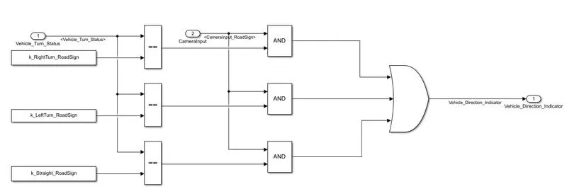
The subsystem consist of three stages. i) The input value from the steering wheel which is compared against the calibrated values using the relational operator and the boolean value is obtained as an output.
ii) The boolean values are compared against the camera input value using a And operator separately and then the all the output are combined to provide the single output.
iii) The vehicle direction detection signal is fed to the outport.
Simulink model
RESULT
The simulink model for the vehicle direction detection is created successfully.