Week 12 - Final Project - Modelling and Analysis of a Datacenter
AIM
The objective of the project is to create a data center model using macros in the Icepak. The main parts of the data center are Computer room air conditioning (CRAC), server cabinets, power distribution units and perforated tiles. Analyze the flow distribution and behaviour of temperature in the server stacks.
Problem Description:
This tutorial considers a 1200 sq. ft. datacenter with a slab to slab height of 12 ft. The datacenter consists of a 1.5 ft underfloor plenum and a 2 ft ceiling plenum. The CRACs discharge cold air into the underfloor plenum. The cold air enters the main datacenter space mainly through the perforated floor tiles and returns back to the air conditioning units. The cooling load, as summarized as below. Size and Capacity of Heat Sources in Datacenter corresponds to the heat output from the server cabinets and the PDUs. A PCB board, library files and traces are imported to create the model. The model is first solved for conduction only, without the components and then solved using the actual components with forced convection.
|
Heat Source |
Size |
Power |
|
Server Cabinet |
2 ft x 3 ft x 7 ft |
3000 W |
|
High Density |
2 ft x 3 ft x 7 ft |
7000 W |
|
PDU |
4 ft x 2 ft x 5 ft |
3600 W |
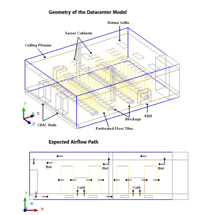
Model
The following objects are created in Icepak using the design specification.
i) Cabinet : It creates a fluid region around the model for which the governing equations are solved.
Geometry
Shape - Prism.
Specified By - Start/end.
Start Xs - 0.
Start Ys - 0.
Start Zs - 0
End Xe - 40ft.
End Ye - 12ft.
End Ze - 30ft.
ii) Raise floor
The plate object is used
Shape - Rectangular.
Plane - X-Z.
Specified By - Start/end.
Start Xs - 0.
Start Ys - 1.5ft.
Start Zs - 0
End Xe - 40ft.
End Ze - 30ft.
iii) Computer room air conditioning (CRAC)
Macros --> Modelling --> Data center componnets --> CRAC.
Specified By - Start/length.
Start Xs - 0.
Start Ys - 0.
Start Zs - 0
Length Xl - 2ft.
Length Yl - 6ft.
Length Zl - 4ft.
Flow direction - -Y.
Fan Specification - Simple.
Intake fan specification
Mass flow rate - 15.9 lbm/s.
Supply temperature - 55F.
Create a group and name it as CRACs
Copy the CRAC & translate the 10ft along Z and create a group and name it as CRACs1.
iv) Rack 1
Macros --> Modelling --> Data center componnets --> Rack (front to rear).
Specified By - Start/length.
Start Xs - 0.
Start Ys - 0.
Start Zs - 0
Length Xl - 3ft.
Length Yl - 7ft.
Length Zl - 2ft.
Flow direction - -X.
Rack specification
Heat load - 3000W.
Volume flow - 450 cfm.
No of racks - 11.
Create additional rack along - +Z.
Create a group and name it as RACKs.
The direction of flow in adjacent rack will be in opposite direction.
Copy the Racks , translate the 7ft along X and rotate around Y axis, angle - 180 and pivot about the centroid & name the group as RACKs
Rack 2
Macros --> Modelling --> Data center componnets --> Rack (front to rear).
Specified By - Start/length.
Start Xs - 22ft.
Start Ys - 1.5ft.
Start Zs - 4ft.
Length Xl - 3ft.
Length Yl - 7ft.
Length Zl - 2ft.
Flow direction - -X.
Rack specification
Heat load - 7000W.
Volume flow - 1100 cfm.
No of racks - 11.
Create additional rack along - +Z.
Create a group and name it as HD RACKs.
The direction of flow in adjacent rack will be in opposite direction.
Copy the Racks , translate the 7ft along X and rotate around Y axis, angle - 180 and pivot about the centroid & name it as HD RACKs.
v) Perforated Tiles
Macros --> Modelling --> data center components --> Tiles.
Plane - X-Z.
No of tiles - 11.
Specify by - Start/length.
Start Xs - 11ft.
Start Ys - 1.5ft.
Start Zs - 4ft.
Length Xl - 2ft.
Length Zl - 2ft.
Create additional tiles along - +Z.
Open Area:
Uniform - 0.35.
Copy the Tiles & translate 2ft along X, create the group & name it as Tile.
Copy the Tile group & translate 14ft along X.
vi) Ceiling
Plane - X-Z.
Specify by - Start/end.
Start Xs - 0.
Start Ys - 10ft.
Start Zs - 0.
EndXe - 40ft.
EndZe - 30ft.
vii) Grille 1
Shape - Rectangular.
Plane - X-Z.
Specified By - Start/length.
Start Xs - 33ft.
Start Ys - 10ft.
Start Zs - 4ft.
Length Xl - 2ft.
Length Zl - 4ft.
Free area ratio - 0.5.
Copy the grille & translate 9ft along Z.
Grille 2
Shape - Rectangular.
Plane - X-Z.
Specified By - Start/length.
Start Xs - 0.
Start Ys - 10ft.
Start Zs - 8ft.
Length Xl - 2ft.
Length Zl - 4ft.
Free area ratio - 0.5.
Copy the grille & translate 10ft along Z.
viii) Power distribution unit
Macros --> Modelling --> Data center componnets --> PDU.
Specified By - Start/length.
Start Xs - 11ft.
Start Ys - 1.5ft.
Start Zs - 0
Length Xl - 4ft.
Length Yl - 4ft.
Length Zl - 2ft.
Bottom to top - Top face - +Y.
Flow direction
Heat load - 3600W.
Percent open area on top - 0.25.
Percent open area on bottom - 0.25 & create the group & name it as PDU.
Copy the grille & translate 14ft along X & 28ft along Z.
ix) Pipe 1
Group name - Blockage.
Specified By - Start/length.
Start Xs - 0.
Start Ys - 0.
Start Zs - 0
Length Xl - 1ft.
Length Yl - 1ft.
Length Zl - 30ft.
Type - Hollow.
Pipe 2
Group name - Blockage.
Specified By - Start/length.
Start Xs - 36ft.
Start Ys - 0.
Start Zs - 22ft.
Length Xl - 4ft.
Length Yl - 12ft.
Length Zl - 8ft.
Type - Hollow.
x) Column
Group name - Blockage.
Specified By - Start/length.
Start Xs - 20ft.
Start Ys - 0.
Start Zs - 0.
Length Xl - 1ft.
Length Yl - 12ft.
Length Zl - 1ft.
Copy the column & translate 20ft along Z.
x) Cable trays
Group name - Blockage.
Specified By - Start/length.
Start Xs - 11ft.
Start Ys - 0.5ft.
Start Zs - 2ft.
Length Xl - -2ft.
Length Yl - 0.5ft.
Length Zl - 24ft.
Copy the column & translate 6ft along X.
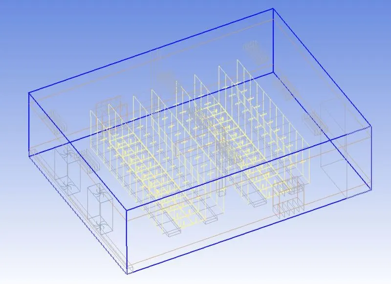
- Macros --> Productivity --> Validation --> Automatic case check tool - It checks the assembly interface between the varies objects and assembly.
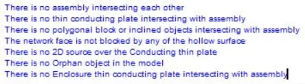
Mesh Control
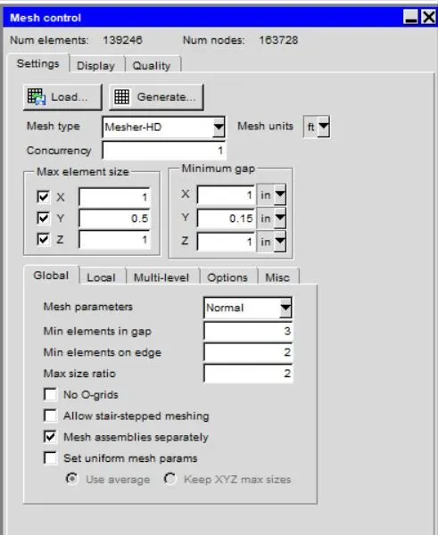
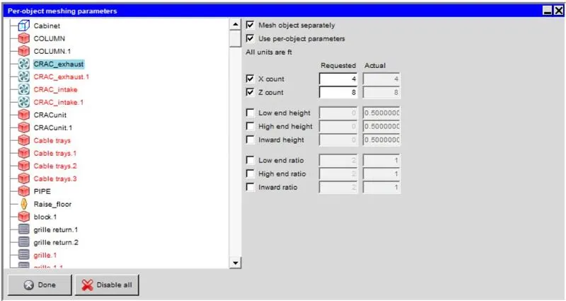
The mesh refinement of the bus bar are done by increasing the element count along the cross section. Select CRAC components --> Set --> object mesh parameter & increase the count value.
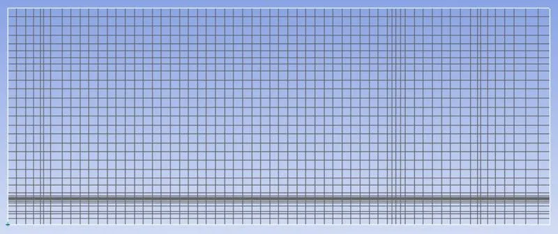
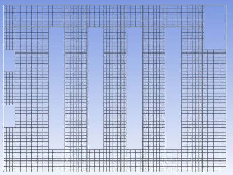
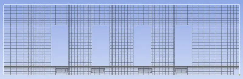
The Mesh for the three plane passing along the center of the control panel.
X Plane
Y Plane
Z Plane
Surface mesh
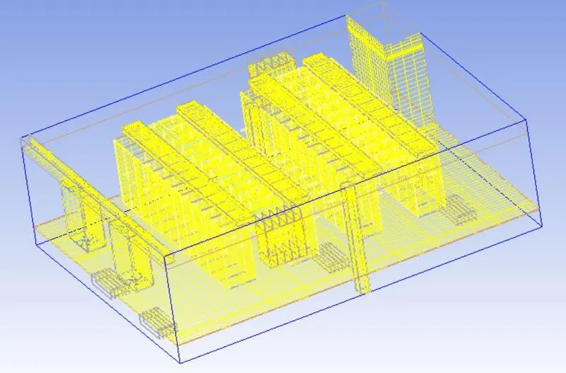
Mesh Verification
Face alignment
- It is the measure of mesh quality defined by face alignment index = C0C1.f
- C0 & C1 are the centroids of two adjacent elements are normal vector to the face between the two elements.
- Range of face alignment 0 (bad) to 1 (good) & value greater than 0.1 (preferred) & value greater than 0.15 provide better results.
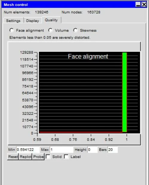
The min value of the model is 0.594 which is ideal for the results.
Volume
- Preferable volume of mesh to be greater than 1e-13 for single precision solver & greater than 1e-15 for double precision.
- Max / Min cell volume should be less than 10^7 for single precision & must be less than 10^12 for double precicion since very small volume create divergence of the solution.
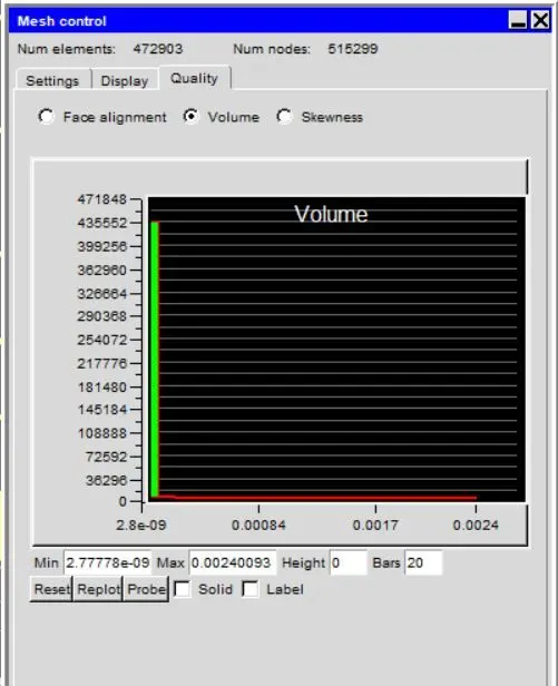
The volume of the mesh greater than 10^-13 & Max / Min cell ratio is around 8.642e5 which is in required range & the double precision is used for this model.
Skewness
It determines how close to the ideal & based on the equilateral volume. The value greater than 0.5 provide good cell quality.
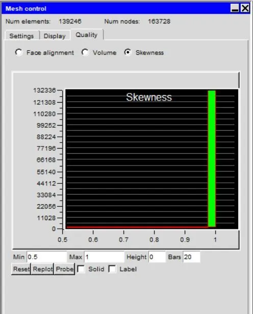
The min value of the skewness is 0.5 so it is ideal for the simulation.
Solver
The three dimensional steady state Navier stokes equations for the model are solved within the computational domain.
General Setup
- Variables solved - flow and temperature.
- Radiation - Off.
- Flow regime - Turbulent - The zero equation are solved for the turbulent model.
Natural convection are consider for this model.
Gravity vector for the y axis is set to -9.81 m/s2.
The defaults value of the parameters are set to default.
Transient Setup
- Time variation - Steady
- Default solid - Mica typical.
- Default surface - Paint non-metallic
Solution Initialization
X velocity - 0.
Y velocity - 0.5 m/s.
Z velocity -0.
Temperature - ambient.
Basic settings
No of iterations - 1000.
Convergence criteria
Flow - 0.0001.
Energy - 1e-10.
Joule heating - 1e-7.
Parallel Settings
Configuration - parallel.
Parallel options - 4 processors.
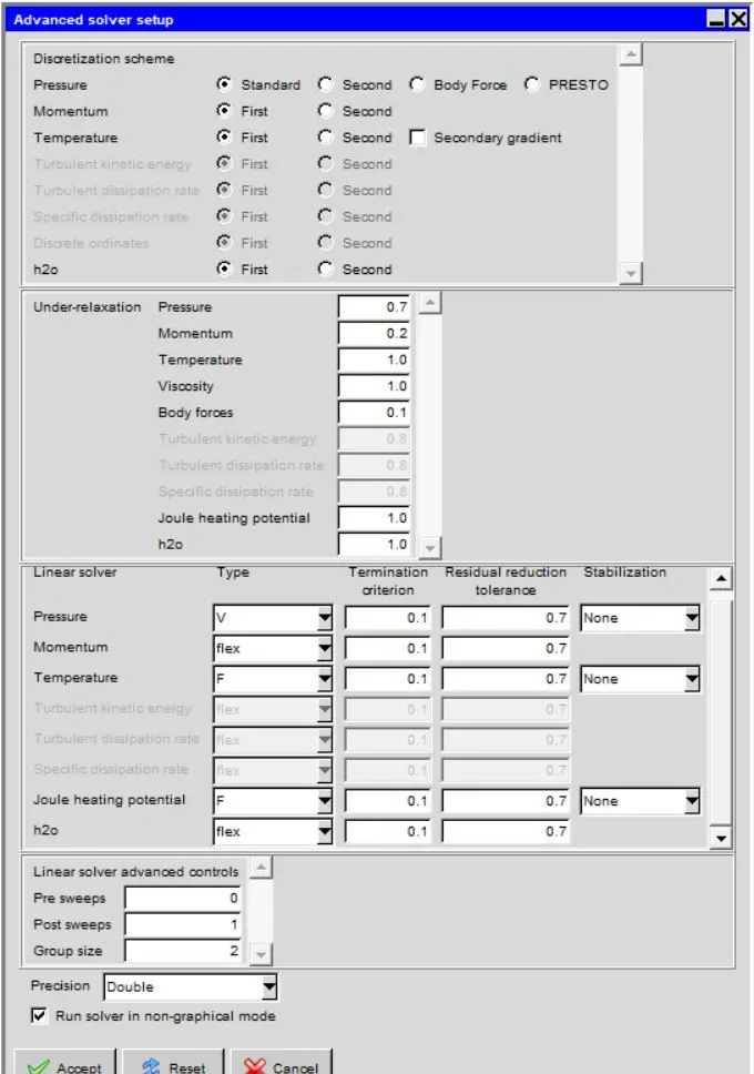
Advance Solver Setup
Results
The residuals for the following equations are plotted against the number of iterations:
- Continuity equation.
- X-momentum equation.
- Y-momentum equation.
- Z-momentum equation.
- Energy equation.
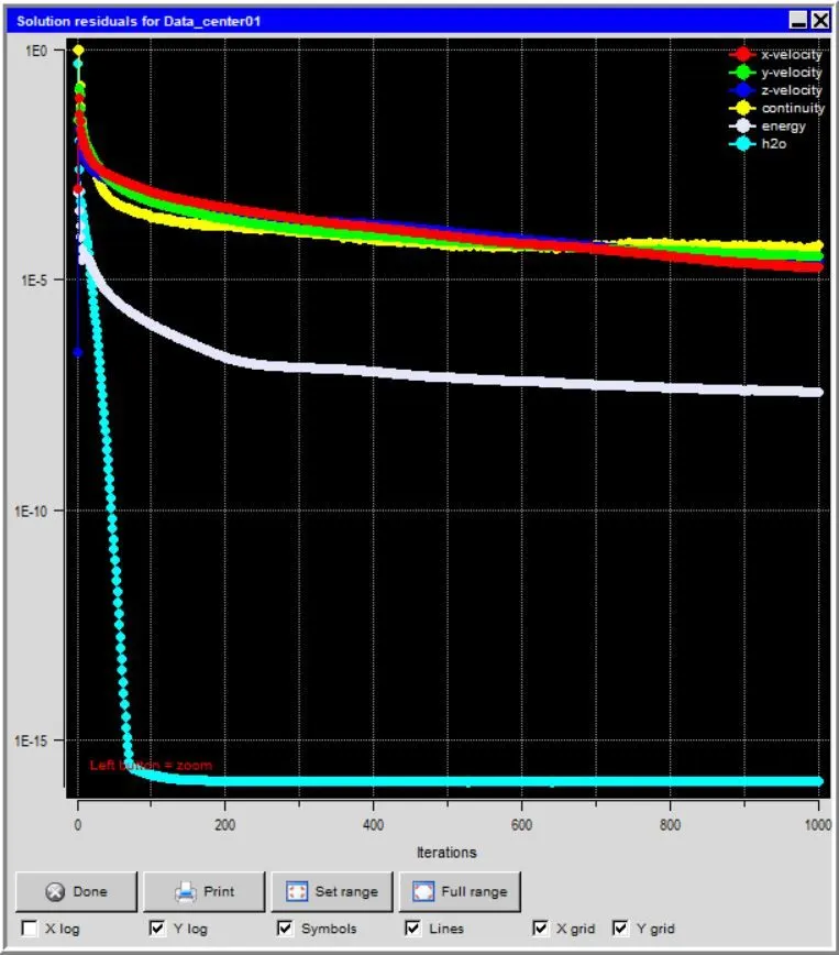
The solution converged around 1000 iterations and the solution has reached a steady state.
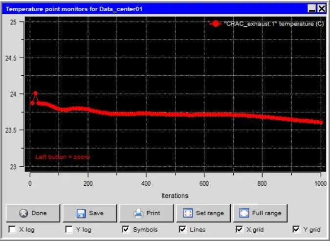
Monitor points
These are probes set at the CRAC Exhaust in the computational domain to determine the temperature variable.
Results
Object face
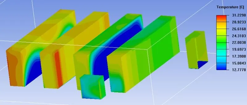
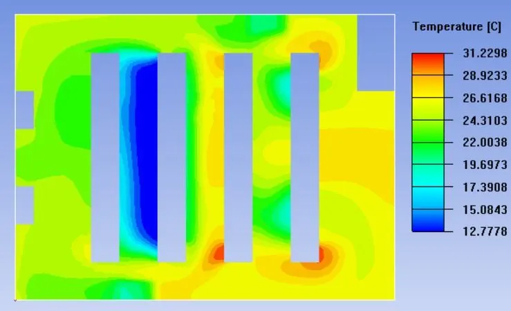
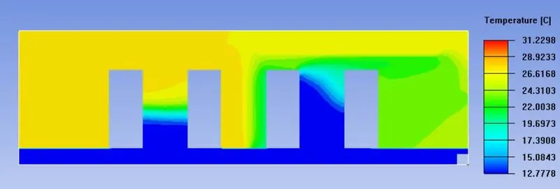
The temperature is lower in the side where the cold fluid flows from the rack and heat dissipated at the elevated temperature on the other side.
Temperature Y plot
Temperature Z Plot
Particle contour
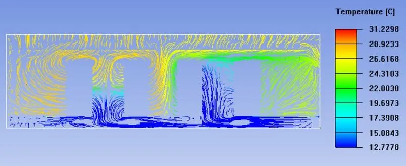
The fluid enter into the system from two CRAC intake and then from the tiles flow moves from bottom to top.