Week 3 - Geometry simplification of an Electronic enclosure assembly
AIM
The objective of the project is convert CAD shapes into Icepak primitive shapes in Spaceclaim & modify the components in Icepak & define the correct physics.
The number of bodies in the CAD model. The functionality of individual bodies or groups of bodies. The required for analysis for the thermal and flow analysis.
Types of bodies
Focus bodies - The bodies which will emit some heat or obstruct the flow of the system.
Necessary bodies - The bodies which will have some effects on the focus bodies.
Peripheral bodeis - These bodies may or may not affect the focus bodies.
Dispensable bodies - The small bodies on the assembly which has no effect on the physics of the system, these bodies are completely neglected.
Geometry Simplification
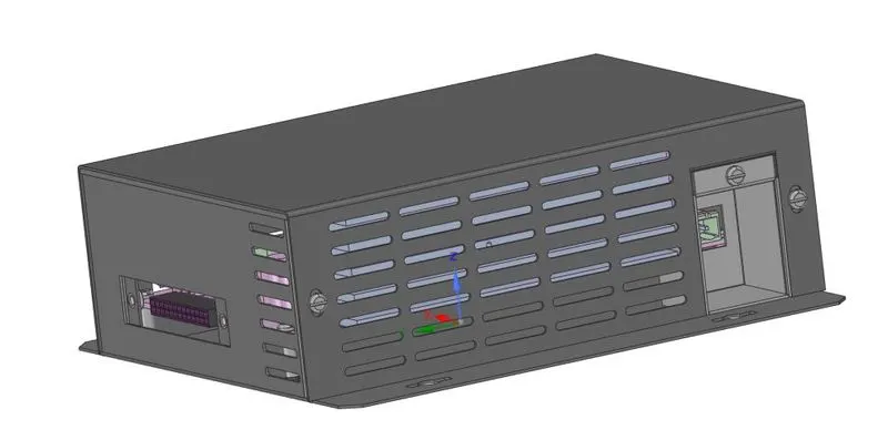
The screw and washer which are used for connecting has no effect on the physics so these bodies are deleted first.
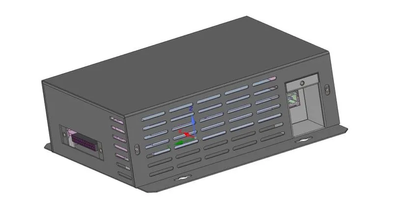
Tools used
Split body - The split body is used to separate a single body into two or delete the uncessary parts from the body. The plane of separation or the face must be chosen for the body separation.
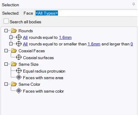
Delete Curvature - The curvature are used to increase the strength of the body which has no effect on flow or thermal analysis & these surface create complexity during the mesh which affect the final solution. Select the fillet & click on selection on the left column which finds all the similar fillet edges & these are deleted using the delete option.
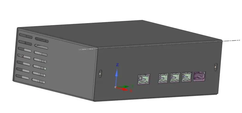
Fill gaps - This option is used to fill gaps around the screws & connector as they are dispensable bodies for our analysis.
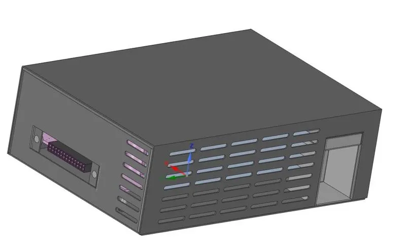
The next step is the segregation of the different bodies depending on the physics used.
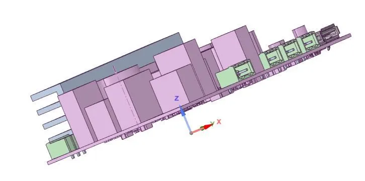
The PCB board has more than 100 components but only the Mosfet, Capacitor, heat sink & processor are used for the simulation so the other small components are deleted.
The components may overlap during the model conversion but these problems must be solved using the split command.
The sketch tool is used to create line & pull command is used to create a surface which acts the plane of separation between the bodies.
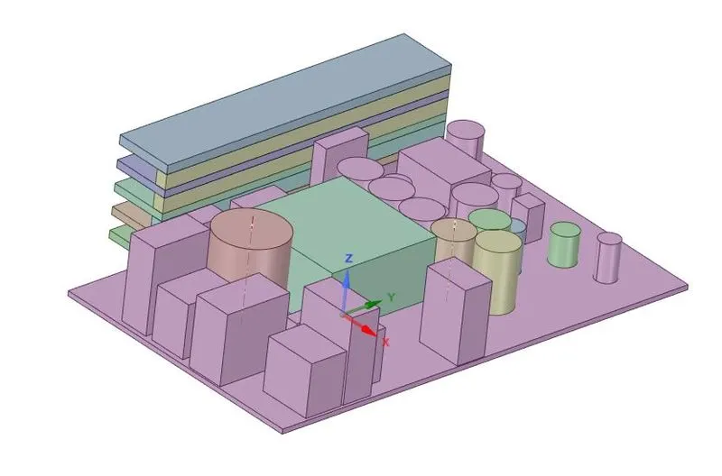
The final model of the PCB in which the connectors and dispensable bodies are deleted.
The next step is to convert the CAD model into icepak objects.
Workbench --> Identify objects - This option converts automatically CAD objects into Icepak objects and other objects are converted using Icepak Simplify option.
Icepak Simplify - It has four different levels to simplify the model.
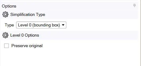
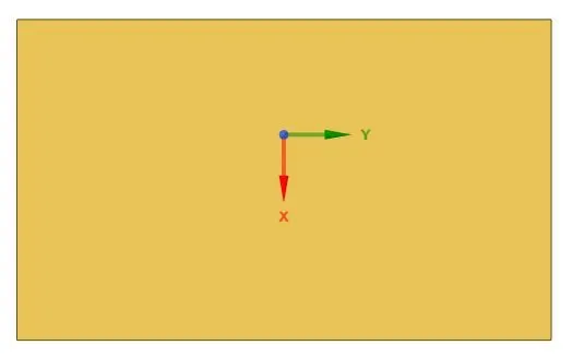
Level 0 - In this level the space claim create a bounding box depending on the minimum and maximum coordinate of CAD geometry. The preserve original option is used to preserve the CAD model after the Icepak object conversion.
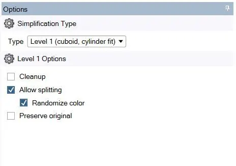
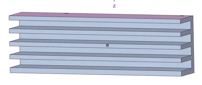
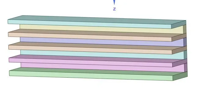
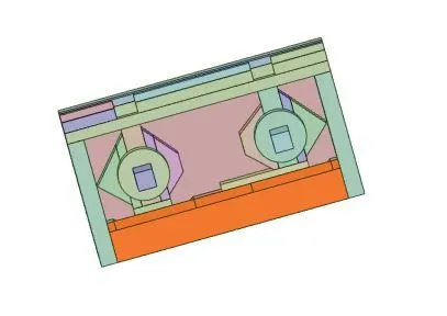
Level 1 - In this level, the geometry gets splits into different levels & it create a primitive shapes to fit the CAD geometry. The allow splitting is used to divide the geometry into small parts to capture the model & randomize color is used to differentiate the splitting the model. The cleanup model is used to simplify the model for the simplification.
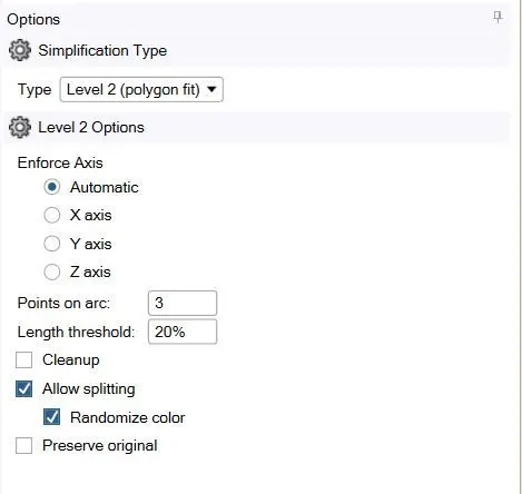
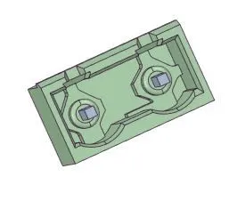
Level 2 - In this level, the polygon are used to capture the CAD model with much more detail to Icepak objects. The Points on arc depicts the division of the line along the curve.
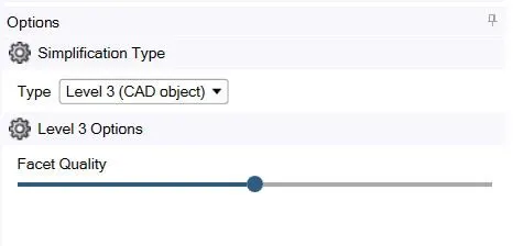
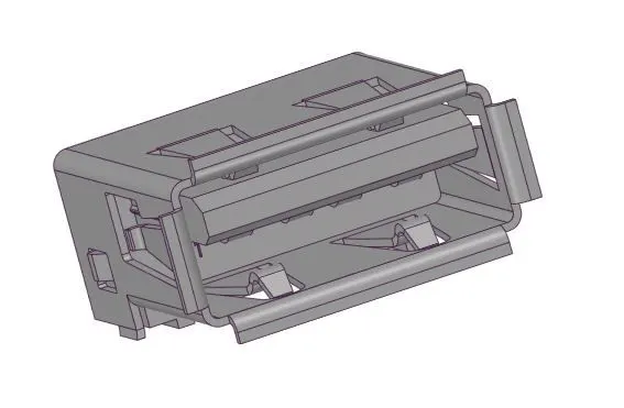
Level 3 - The object is directly converted from CAD model to Icepak object. The quality of the icepak object depend on the facet quality we set. Higher value we set higher quality of the Icepak object can be converted.
Depending on the requirement the level of simplification & the required level of the model are created.
Level 0 Conversion
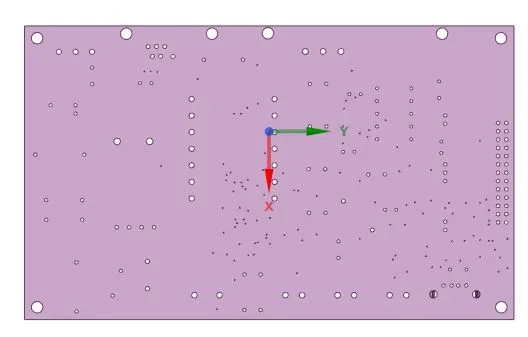
Level 1 Conversion
Level 2
Level 3
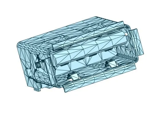
By this method all the object are converted into the Icepak objects.
Grille option is selected at the inlet face for the cooling of the PCB board.
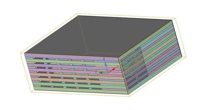
Icepak
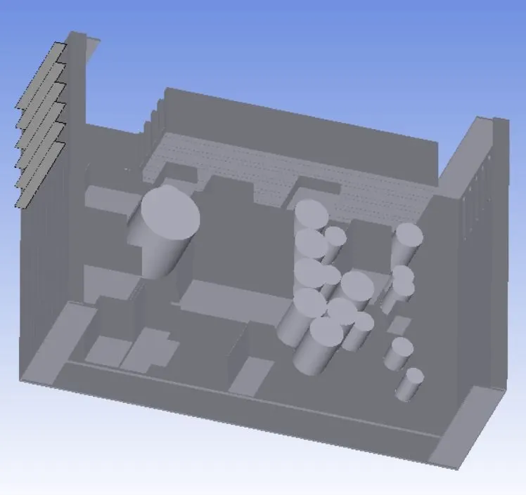
The size of the object is reduced in the interfereing regions by selecting of the object & reducing the dimension of the object.
Final Model
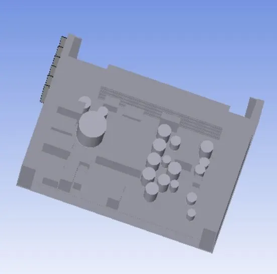
Macros --> Productivity --> Validation --> Automatic case check tool - This option check for the model on various criteria.
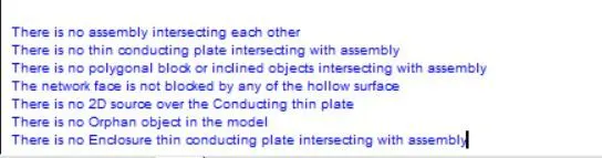
The CAD model is successfully converted into Icepak object & the different errors in the model are corrected. The model is meshed & the required setup for the physics is provided & the solution run for the simulation.