Project 1 : CFD Meshing for Tesla Cyber Truck
AIM: To perform INTERNAL ANALYSIS on WIND TUNNEL with given model present in it. Has to perform Pre-Processing of CFD which is required on given model and on wind tunnel viz; Geometry Cleanup, Surface Meshing and Volumetric Meshing on given Wind tunnel.
(#WIND TUNNEL WORKING PRINCIPLE
How Do Wind Tunnels Work?
Wind tunnels usually have powerful fans to move the air through the tube. The object being tested is placed in the tunnel so that it will not move. The air moving around the still object shows what would happen if the object were moving through the air. The object can be a smaller-scale model of a vehicle, one piece of a vehicle, a full-size aircraft or spacecraft, or even a common object like a tennis ball. Usually, the object carries special instruments to measure the forces produced by the air on the object. Engineers also study how the air moves around the object by injecting smoke or dye into the tunnel and photographing its motion around the object. Improving the flow of air around an object can increase its lift and decrease its drag.
Data Taken From:https://www.nasa.gov/audience/forstudents/5-8/features/nasa-knows/what-are-wind-tunnels-58.html
)
PROCEDURE: It is clear from the working principle that to perform internal analysis of WIND Tunnel with given model in it, we need to isolate the given model in such a way that the whole model should be made as a single volume at the stage of Geometry cleanup of the model. There is no need of Internal analysis of given model. Here I did only EXTERNAL analysis of it as it suffice the procedure.
So, I divided the whole process into stages.
STAGE 1: Procedures on given model (TESLA CYBERTRUCK).
a) GEOMETRY CLEANUP
b) SURFACE MESHING
STAGE 2: Procedures on Wind Tunnel.
a) Creation of Wind Tunnel with required Boundary conditions
b) GEOMETRY CLEANUP (Needed)
c) SURFACE MESHING
d) VOLUMETRIC MESHING
STAGE 1: Procedures on given model (TESLA CYBERTRUCK).
a) GEOMETRY CLEANUP: Performed Geometric analysis using CHECKS MANAGER>GEOMETRY CHECKS in TOOLS feature.Found penetration and geometrical errors in the model.Performed needed cleanup and assigned PIDs for different sections based on the classifaction of working principle.
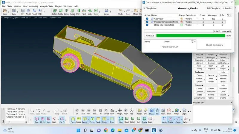
Checked by changing the RESOLUTION of the given model using TOOLS>SETTINGS>RESOLUTION to 1mm. Model was found same as before.
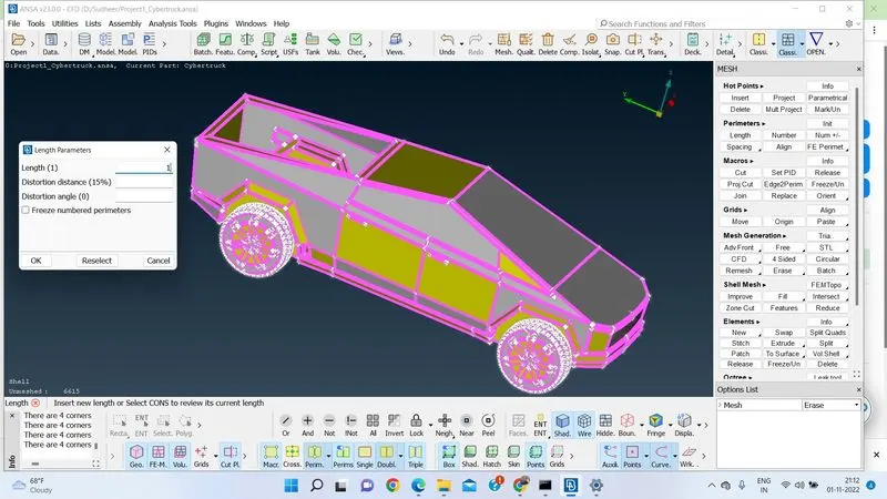
By observing the given model, came to a coclusion that it is a Axisymmetric body. If we cut the body at centre it is easy to perform the needed work and later we can mirror the body. As it is axisymmetric no change of parts will be there. So, I divided whole Geometry into two halves using TOPO > FACES > CUT PLANE.
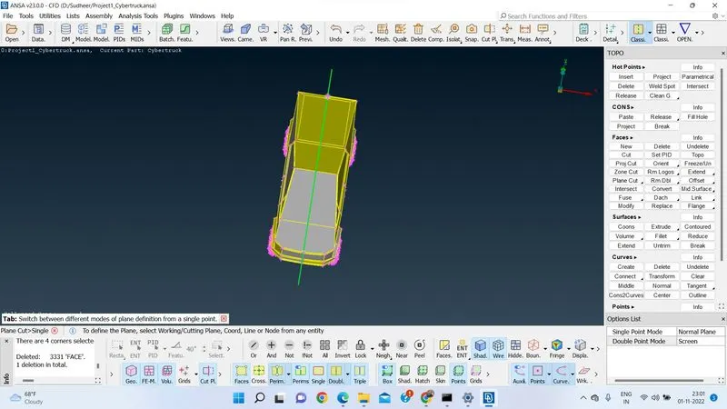
Performed GEOMETRICAL CLEANUP using various features in TOPO tool at each local level and global level.Used HOT POINTS, FACES,CONS, FACES, CURVES, POINTS as per the requirement.
b) SURFACE MESHING :
After Geometry cleanup PIDs are assigned to identify each object using PID tool.Compressed further to delete unassigned entities using COMPRESS tool.
It is given in the problem statement to follow prior model (BMW M6-Car) for Meshing procedure. So, Here followed the same.
ELEMENT TYPE= TRIA,
MESH TYPE= CFD MESH,
ORDER =1st ORDER,
TARGET LENGTHS: Body=3mm,
Windows=2mm,
Tyres and Rims=2mm,
Lights=4mm.
For Rims and Tyres ,Window as per the given instructions taken the tria element, with target size of 2mm, min/max length as 2.5/1.5mm in mesh quality parameters respectively. Used CLASSIC MESH>PARAMETERS>SPACING >AUTO CFD algorithm for spacing elements. For mesh Generation used MESH GENERATION> CFD>VISIBLE algorithm as it gives better results.
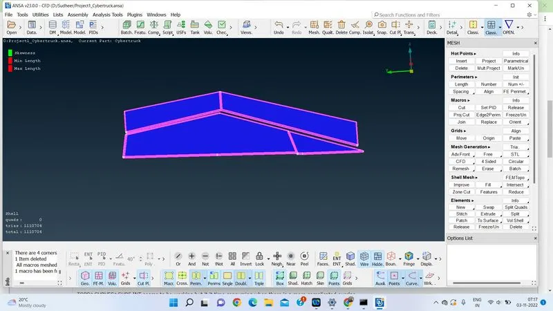
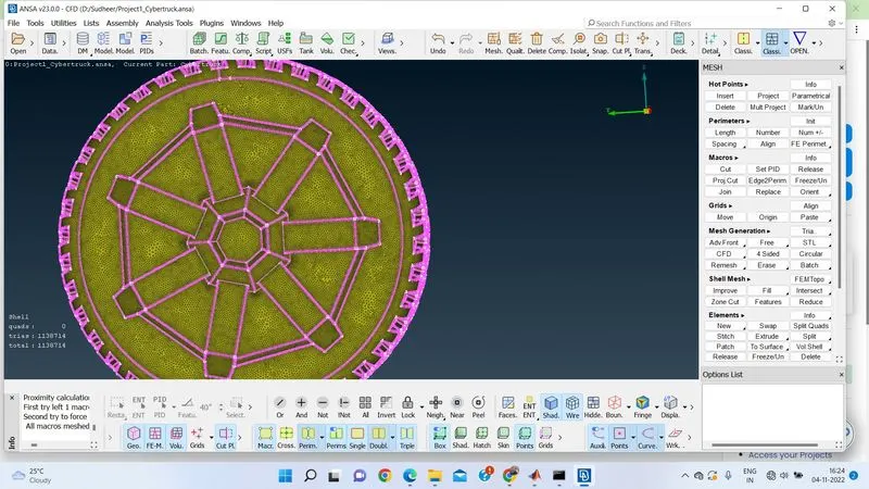
As these parts are given different perimeters for the compliance different meshing elements used MACROS>FREEZE option.
For body of the truck as per the given instructions taken the tria element, with target size of 3mm, min/max length as 2.5/3.5mm in mesh quality parameters respectively. Used CLASSIC MESH>PARAMETERS>SPACING >AUTO CFD algorithm for spacing elements. For mesh Generation used MESH GENERATION> CFD>VISIBLE algorithm as it gives better results.
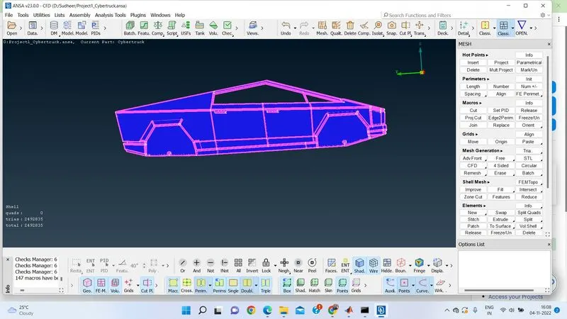
As these parts are given different perimeters for the compliance different meshing elements used MACROS>FREEZE option.
For Lights as per the given instructions taken the tria element, with target size of 4mm, min/max length as 3.5/4.5mm in mesh quality parameters respectively. Used CLASSIC MESH>PARAMETERS>SPACING >AUTO CFD algorithm for spacing elements. For mesh Generation used MESH GENERATION> CFD>VISIBLE algorithm as it gives better results.
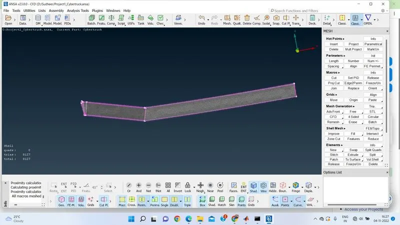
As these parts are given different perimeters for the compliance different meshing elements used MACROS>FREEZE option.
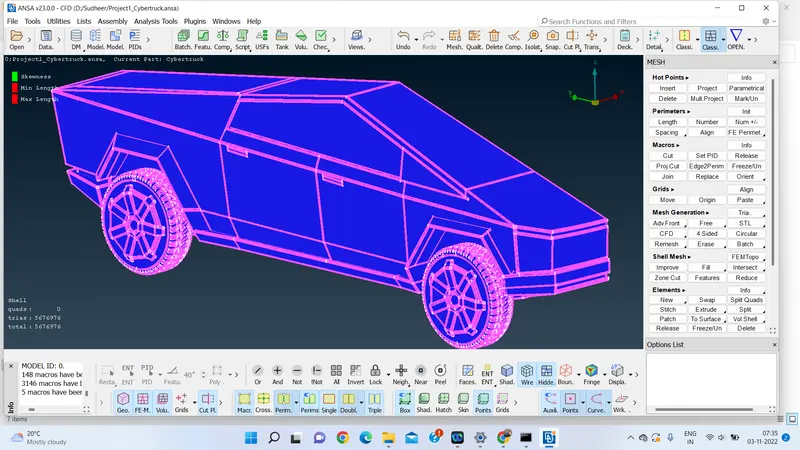
After cleaning up the model, as it is is AXISYMMETRICAL in nature mirrored the bisected portion of the car using TRANSFORM feature 3-Point SYMMETRY method.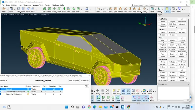
NO Geometrical errors found when checked with CHEKS MANAGER option. Found the results obtained are satified.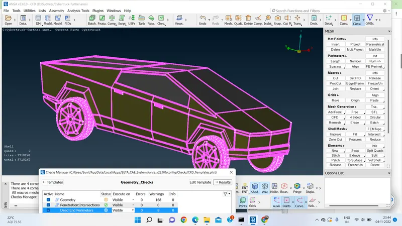
Found NO OFF elments. MOdel is as per the given QUALITY PARAMETERS>SHELL PARAMETERS> SKEWNESS:0.5,MIN LENGTH=0.1,MAX LENGTH =6. It is taken into consideration based on the highest and least target length of the elements.
STAGE 2: WIND TUNNEL creation
Based on length and width of car constructed a box shaped wind tunnel with certain dimension.All are in mm.
car dimension is 5906 mm. Taken X as approx 6000.
From front face of 3000+4*6000=27000
From back face 3000+6*6000=39000
on Sides=3*6000=18000
On bottom =1500
On top=1500+3*6000+1500=21000.
Created box shaped tunnel.
Meshed with bottom face as 30mm and top face as min/max 20/40mm, 100mm min/max 80/120 with growing element size.
Found satisfactory with results.
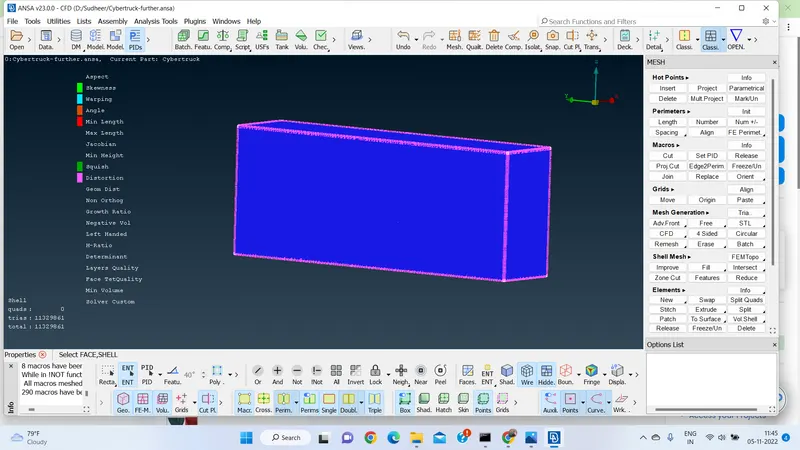
Found NO OFF elments. Obtained results are satisfactory.
RESULT : Geometry cleanup and Meshing has been done properly with given target length of elements. Resuults obtained are satisfactory.
CONCLUSION: As per the given statement model is prepared at PRE_PROCESSING STAGE (Except Volumetric meshing).
NOTE Unable to upload ANSA file, attaching STEP file.