Week 9 - Parametric study on Gate valve.
A PARAMETRIC STUDY OF GATE VALVE
AIM:To perform a parametric study on the gate valve simulation by setting the opening from 10 % to 80%.
- Obtain the mass flow rates at the outlet for each design point.
- Calculate the flow coefficient and flow factor for each opening and plot the graph.
- Discuss the results of the mass flow rate and flow coefficient.
INTRODUCTION:
GATE VALVE:
A gate valve is a type of valve that controls the flow of liquids and gases through a pipe by opening or closing a gate. The gate is typically a flat disk that moves up and down in a vertical or horizontal direction to control the flow. Gate valves are often used in industrial and commercial settings to regulate the flow of water, steam, oil, and other fluids. They are typically made of metal, such as brass, bronze, or stainless steel, and are designed to withstand high pressure and temperature. They can be operated manually or with the use of actuators such as pneumatic or electric motor.
Different types of Gate Valves:
There are several types of gate valves, each with its own unique features and applications. Some of the most common types include:
-
Solid Wedge Gate Valve: This type of valve has a solid wedge-shaped disc that moves up and down to open and close the valve. Solid wedge gate valves are typically used in applications where tight shut-off is required and can handle a wide range of pressure and temperature conditions.
-
Flexible Wedge Gate Valve: This type of valve has a flexible wedge-shaped disc that flexes to conform to the contours of the valve body, providing a tight seal. Flexible wedge gate valves are typically used in applications where moderate to high pressure and temperature conditions are present.
-
Split Wedge Gate Valve: This type of valve has a split wedge-shaped disc that moves up and down to open and close the valve. Split wedge gate valves are typically used in applications where tight shut-off is required and can handle a wide range of pressure and temperature conditions.
-
Parallel Slide Gate Valve: This type of valve has a disc that moves parallel to the valve body to open and close the valve. Parallel slide gate valves are typically used in applications where moderate to high pressure and temperature conditions are present.
-
Rising Stem Gate Valve: This type of valve has a stem that rises and falls with the movement of the gate. Rising stem gate valves are typically used in applications where tight shut-off is required and can handle a wide range of pressure and temperature conditions.
-
Non-Rising Stem Gate Valve: This type of valve has a stem that does not rise and fall with the movement of the gate. Non-rising stem gate valves are typically used in applications where tight shut-off is required and can handle a wide range of pressure and temperature conditions.
-
Knife gate valve: This type of valve has a sharp-edge disc which is perpendicular to the flow, the disc moves up or down to open or close the valve, it is typically used in industries such as mining, pulp and paper, and wastewater treatment.
-
Cryogenic gate valve: This type of valve is designed to handle low temperatures, typically below -196 °C, it is typically used in industries such as LNG, petrochemical, and aerospace.
These are some examples of common types of gate valves, but it's worth noting that there are many variations and sub-types within each category, each with its own unique features and applications.
Gate valves are commonly used in industrial and commercial settings to control the flow of liquids and gases in a variety of applications, including:
-
Water distribution systems: Gate valves are often used to control the flow of water in municipal and industrial water distribution systems.
-
Oil and gas industry: Gate valves are used in the oil and gas industry to control the flow of liquids and gases in pipelines and storage tanks.
-
Steam systems: Gate valves are used in steam systems to control the flow of steam in boilers, heat exchangers, and other equipment.
-
Power generation: Gate valves are used in power generation plants to control the flow of fluids in cooling systems, fuel systems, and other applications.
-
Chemical processing: Gate valves are used in chemical processing plants to control the flow of chemicals in pipelines and storage tanks.
-
Mining: Gate valves are used in mining operations to control the flow of liquids and gases in pipelines and equipment.
-
HVAC Systems: Gate valves are used to control the flow of fluids in heating, ventilation and air-conditioning systems.
-
Marine: Gate valves are used to control the flow of liquids and gases in ships and other marine vessels.
Overall, gate valves are versatile valves that can be used in a wide range of applications where it is necessary to fully open or fully close the flow of liquids and gases.
FLOW COEFFICIENT:
The flow coefficient, also known as the Cv coefficient, is a measure of the capacity of a valve to flow a fluid. It is defined as the flow rate of water in litres per minute (lpm) at 15 degrees Celsius that will pass through the valve with a 1 kiloPascal (kPa) pressure drop. The flow coefficient can be used to compare the relative flow capacities of different valves, or to size a valve for a specific application.
The flow coefficient is a dimensionless number, and is typically determined through testing in accordance with industry standards, such as the Indian Standards (IS) or the Bureau of Indian Standards (BIS).
It is important to note that the flow coefficient is only applicable for a specific set of conditions, such as a specific fluid and a specific pressure drop. The flow coefficient can change depending on the fluid, pressure, and temperature.
In summary, the flow coefficient (Cv) is a measure of the capacity of a valve to flow a fluid, and is typically used to compare the relative flow capacities of different valves or to size a valve for a specific application. It is a dimensionless number, which is determined through testing under specific conditions and in Indian metric system.
Mathematically the flow coefficient Cv (or flow-capacity rating of valve) can be expressed as:
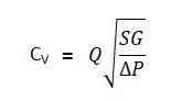
Where:
- Q is the rate of flow (expressed in US gallons per minute).
- SG is the specific gravity of the fluid (for water = 1).
- ΔP is the pressure drop across the valve.
FLOW FACTOR:
The flow factor, also known as the Kv coefficient, is similar to the flow coefficient (Cv) in that it is a measure of the capacity of a valve to flow a fluid. However, the Kv coefficient is typically used in the metric system and is defined as the flow rate of water in cubic meters per hour (m³/h) at a pressure drop of 1 bar. Like the Cv coefficient, the Kv coefficient is a dimensionless number and is typically determined through testing in accordance with industry standards.
It is important to note that the flow factor is only applicable for a specific set of conditions, such as a specific fluid and a specific pressure drop. The flow factor can change depending on the fluid, pressure, and temperature.
In summary, the flow factor (Kv) is a measure of the capacity of a valve to flow a fluid, and is typically used to compare the relative flow capacities of different valves or to size a valve for a specific application. It is a dimensionless number, which is determined through testing under specific conditions and in Indian metric system.
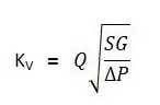
Where:
- Kv is the flow factor (expressed in). Q is the flow rate (expressed in cubic meters per hour.
- SG is the specific gravity of the fluid (for water = 1).
- ∆P is the differential pressure across the device (expressed in [bar]).
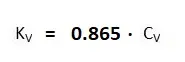
Kv can be calculated from Cv using the equation as given below:
PARAMETRIC STUDY:
Parametric studies in ANSYS can be used to assess the impact of different design parameters on the performance of a given system or product. This can help designers optimize their designs and make better-informed decisions. Some common uses of parametric studies in ANSYS include:
-
Optimization of design: Parametric studies can be used to identify the optimal design by varying parameters such as geometric dimensions, material properties, and loads and analyzing the results to identify the configuration that best meets the design criteria.
-
Sensitivity analysis: Parametric studies can be used to identify which parameters have the greatest impact on the performance of a given system or product. This can help designers focus on the most critical parameters and make more efficient use of their resources.
-
Exploring the design space: Parametric studies can be used to explore the design space and identify design options that may not have been considered previously.
-
Investigating the effects of uncertainties: parametric studies can be used to investigate the effects of uncertainties in parameters such as loads, boundary conditions, and material properties on the performance of a given system or product.
-
Automation of repetitive tasks : parametric studies can be used to automate repetitive tasks such as running a simulation with different parameter values or creating different design configurations.
PROCEDURE:
To perform analysis on Gate valve flow capacity ,I used ANSYS Fluent which is widely used in this industry. Here we need to analyse using CFD techniques to perform a simulation which represents the real time flow conditions.
Here we are performing the simulation by lifting the gate valve in stepwise manner. And observing the mass flow rate with respect to the lift of gate disc. By parameterizing the lifting length we can see the results without running simulation every time. It also reduces computational time and automate the calculation.
In CFD, analysis is divided into steps. PreProceesing/Geometry Cleanup, Meshing, Setup for Solving the flow dynamics, Solution, Post Processsing.
PrePreocessing/Geometry Cleanup:
- Used STEP file of Gate Valve into ANSYS SpaceClaim tool to perform some preprocessing requirements to be made for simulation of flow through it.
- To study the flow pattern, extended the inlet and outlets of the Valve to 0.8m on both sides.
- Fluid flow volume has been extracted.
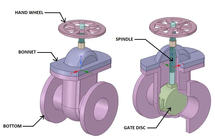
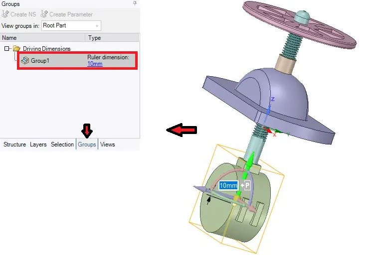
- As per the functioning of the valve, to allow the fluid to flow the spindle has to be rotated as a result the GATE DISC which restricts the flow will rise to the desired height. It can be called as LIFT of the valve.
- LIFT is made as a PARAMETER. With this parameter we are calculating flow fro 10mm lift to 80mm lift with an increment of the flow of 10mm for every simulation.
MESHING:
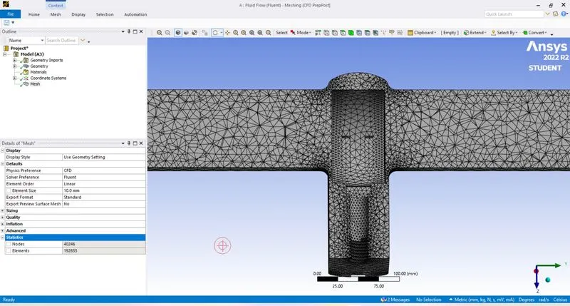
With 10mm mesh element side the following were the results obtained of 192655 elements. Quality of the elements is found satisfactory.Assigned Named conventions for inlet and outlet.
SETUP:
General Settings:
Analysis type: Steady state
Solver: Pressure based solver
Gravity: -9.81 m/s2 in Z-Direction
Material Specifications:
Material: water-liquid (h2o)
Chemical Formula: H2O
Density: 998.2 Kg/m3
Viscosity: 0.001003 Kg/ (m-s)
Viscous Model:
Model: K-Epsilon
K-Epsilon Model: Realizable
Near Wall Treatment: Standard Wall Functions
Boundary Conditions:
Inlet: Pressure-Inlet
Gauge Total Pressure: 10 Pa
Outlet:Pressure-outlet
Gauge Total Pressure: 0 Pa
Initialization:
Standard Initialization
Because of standard initialization y-component velocity is 0.1415488m/sec. From this, Reynolds number for this flow is calculated as 14087.14.
CASE 1: Lift=10mm
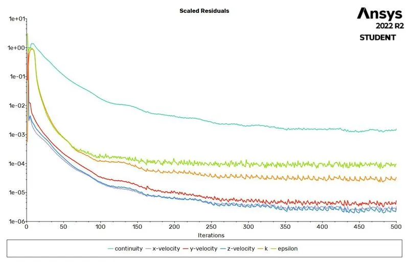
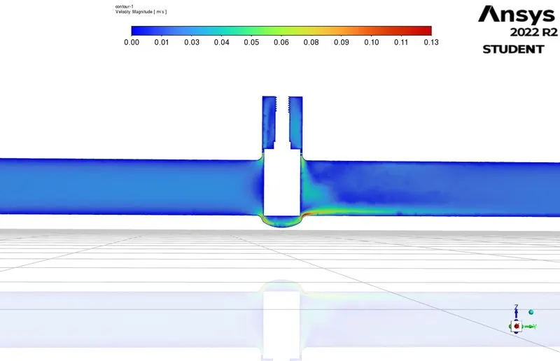
Below are the Scaled residuals and masflow rate at outelt plots. Mass flow rate plot indicates that flow is stabilizes in very less time.
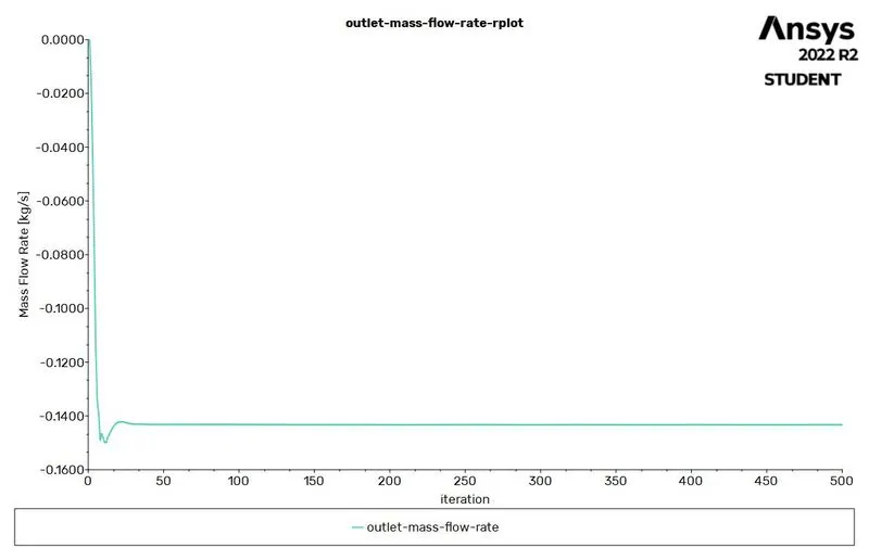
Mass Flow rate Outlet: 0.14328 kg/sec for 10mm opening.
Flow Coefficient = -0.0453
Flow Factor=-0.0391
From velocity plot it can be observed that fluid is flowing and having high velocity at corners of gate disc shape in the gate valve.
As I parameterized the flow simulation, used it to run the remaining lift points.Obtained the following results.
| Name | Gate Valve Opening mm |
inlet- mass-flow-rate [kg s^-1] |
outlet- mass-flow-rate [kg s^-1] |
Flow Coefficient | Flow Factor |
| DP 0 | 10 | 0.14328186 | -0.14328002 | -0.04530901088 | -0.03919229442 |
| DP 1 | 20 | 0.22977707 | -0.22979195 | -0.07266641897 | -0.06285645241 |
| DP 2 | 30 | 0.38025819 | -0.37251761 | -0.1178001263 | -0.1018971092 |
| DP 3 | 40 | 0.45521276 | -0.45523477 | -0.1439575256 | -0.1245232597 |
| DP 4 | 50 | 0.53768344 | -0.5374145 | -0.1699449751 | -0.1470024035 |
| DP 5 | 60 | 0.63497547 | -0.63465498 | -0.2006950404 | -0.1736012099 |
| DP 6 | 70 | 0.70979045 | -0.70973581 | -0.224437626 | -0.1941385465 |
| DP 7 | 80 | 0.78659997 | -0.7867962 | -0.2488062019 | -0.2152173647 |
NOTE: Negative sign indicates the flow here is going out.
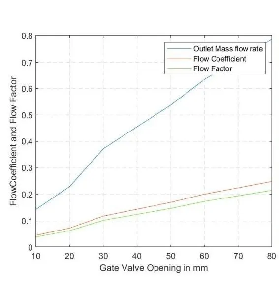
If we observe the results, it appears that as the opening of the gate valve increases, the inlet and outlet mass flow rates also increase. The flow coefficient and flow factor also increase with increasing valve opening.
CONCLUSION:
Our observations show that as the opening of the gate disc increases, the velocity of the flow also increases. At the inlet side of the valve, the pressure is high but it decreases as the flow passes through the valve opening. On the outlet side, there are no restrictions to the flow, resulting in a pressure of 0, and minimal pressure drop. As the lift of the gate disc increases, from 10% to 80% or 10mm to 80mm, we see a gradual increase in the mass rate, flow coefficient, and flow factor. When the valve is fully open, the mass flow rate, flow coefficient, and flow factor reach their maximum values. In summary, conducting a parametric study of the different positions of valve opening can provide quick and easy results on the behavior of the valve.
References: