Week 2 - Flow over a Cylinder.
A STUDY ON FLOW OVER A CYLINDER
&
KARMAN VORTEX EFFECTS ON THE FLOW
AIM: To perform External flow analysis over a bluff body(Circular Cylinder) of 2m Diameter in 2-Dimensional manner, to study the certain aerodynamic forces Coefficients of Lift & drag forces which were in-line and transverse direction, based on Reynolds Number. And to understand the instabilities in the flow like periodic fluctuations ,with help of Strohaul Number.
Introduction:
A bluff body is an object in aerodynamics that has a length in the direction of flow that is close to or equal to its length perpendicular to the flow direction. This means that the contribution of skin friction to the overall force on the body is much lower than that of pressure. Even a streamlined body, like an airfoil, can behave like a bluff body at large angles of incidence. A circular cylinder is often used as a model for studying bluff body flows. These flows are characterized by flow separation, which creates a region of disturbed flow behind the body known as the wake. As the Reynolds number (a dimensionless number that describes the ratio of inertial forces to viscous forces) is increased, various forms of flow instabilities can occur in the near-wake region. These instabilities can manifest as two- or three-dimensional unsteady flow structures and eventually turbulence. The most well-known instability is the periodic formation and shedding of spanwise vortices, which creates a characteristic wake pattern. The frequency of vortex shedding is described by the Strouhal number. Bluff body flows involve the interaction of three shear layers: the boundary layer, the separating free shear layers, and the wake. Controlling the separated flow in the wake and the dynamics of vortex formation can be used to modify the aerodynamic characteristics of bluff bodies. This can be done through active methods, such as introducing perturbations to the wake flow, or passive methods, such as modifying the body's geometry.
Reynolds Number:
It is a dimensionless quantity that is used to characterize the flow of a fluid. It is defined as the ratio of the inertial forces to the viscous forces in a fluid, and is commonly used to predict whether a given flow will be laminar or turbulent. The Reynolds number is calculated using the following formula:
Re = (density of the fluid * velocity * characteristic length) / (viscosity of the fluid)
The Reynolds number is named after the 19th-century British scientist Osborne Reynolds, who first proposed the concept. It is a very important parameter in fluid dynamics, as it is used to determine the type of flow that will occur in a given system. Laminar flow, which is characterized by smooth, orderly motion, typically occurs at low Reynolds numbers, while turbulent flow, which is characterized by chaotic, swirling motion, typically occurs at high Reynolds numbers.
Strouhal Number:
Strouhal number is a dimensionless quantity used in fluid dynamics to predict the formation and shedding of vortices in a fluid. It is defined as the ratio of the vortex shedding frequency to the flow velocity, and is often used to study the behavior of fluids around objects such as cylinders and spheres. The Strouhal number is typically denoted by the symbol "St," and is calculated using the following formula:
St = (frequency of vortex shedding * characteristic length) / flow velocity
The Strouhal number is named after the 19th-century Czech physicist Vincenc Strouhal, who first proposed the concept. It is an important parameter in many areas of fluid dynamics, as it is used to predict the performance of systems such as pumps and turbines, as well as the aerodynamics of objects moving through a fluid.
Vortex Shedding:
Vortex shedding is a phenomenon that occurs when a fluid flows around an obstacle, such as a cylinder or sphere. As the fluid flows past the obstacle, vortices, or whirlpools, are formed on the downstream side of the obstacle. These vortices alternate between the left and right sides of the obstacle, and can cause a periodic fluctuation in the fluid flow known as vortex shedding. Vortex shedding can have significant effects on the performance of systems such as pumps and turbines, and is also important in the study of aerodynamics. It is typically studied using computational fluid dynamics (CFD) simulations and experiments, and can be predicted using dimensionless quantities such as the Reynolds number and the Strouhal number.
The coefficient of drag and lift are the function of respective lift and drag force with density of fluid and velocity with exposure area in front. The equation for coefficient of lift and drag is given as:
Cd=2⋅Fdρ⋅V2⋅A">Cd=2⋅Fd/ρ⋅V^2⋅A
Cl=2⋅Flρ⋅V2⋅A">Cl=2⋅Fl/ρ⋅V^2⋅A
Where,
Fd and Fl are drag force and lift force respectively.
ρ = Density of Fluid
V = Velocity of Fluid
A = Frontal Area.
Reference: https://www.researchgate.net/publication/234006090_Bluff_Body_Aerodynamics_and_Wake_Control
To analyze the flow behaviour, i am going to use ANSYS FLUENT software.
Modelling of the Flow around Cylinder in a Tunnel:
Basic Physics Setup:
Object:
Cylinder Dimensions(Considering The calculations are going to perform in 2-D)
Length of Cylinder =1m
Diameter of Cylinder=2m
Flow Type:
Laminar Flow
Assuming the flow is steady with Reynolds number Re=10.
Flow Medium:
Medium : Air(Custom Properties)
Density of air=1 kg/m^3
viscosity = 0.05 kg/m-s.
Re=(ρVL)/μ
∴V=(Re⋅μ)/ρ⋅L=10*0.05/1*2=0.25m/s.
Resulting with Velocity of fluid flow V=0.25m/s.
ANSYS SETUP:
The study we are performing is aimed at visualizing the flow pattern in order to gain a better understanding of the behavior of flow for various Reynolds numbers. This is done using a commercial CFD software package that includes all stages of the CFD process, such as geometry cleanup/creation, meshing, solving, and post-processing. By using this software, we are able to simulate the flow of fluids and analyze the resulting data to gain insights into the behavior of the flow.
ANSYS FLUENT FLOW:
The whole study is performed under various Reynolds numbers which describes the flow type velocity of Re=10,100,1000,10000 with steady state and one case under Transient state.
1)GEOMETRY CREATION
STEADY FLOW
For Reynolds Number 10
WIND TUNNEL:
Below is the setup created by using Spaceclaim SKETCH tool in Fluent.
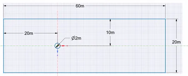
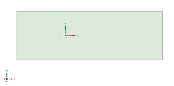
In above geometry sketch we can see cylinder of 2m diameter which is immersed in the fluid domain of 20 x 60 m dimension. The inlet of domain is 20m left from center of cylinder and outlet is 40m right from center of cylinder. There is no thickness provided to the geometry as it is a 2D simulation. After providing the details the geometry will be:
2)MESHING:
The meshing stage of the CFD process involves creating a small, discrete domain on which the governing equations of fluid flow can be solved. The mesh should be fine enough to capture the details of the flow, such as changes in velocity or pressure, that may occur during the simulation. In this case, the mesh size used for both the Steady state and Transient state solver is 250mm for the entire domain. Being a Circular geometry we are using All triangular Elements method.
It is important to capture the flow around the cylinder accurately, as this is where flow separation may occur. To capture the flow near the cylinder, an inflation layer is used. The inflation layer creates a hexahedral mesh near the cylinder, which helps with solution convergence and provides more accurate results. It also helps in a smooth volume transition from cylinder to the free space or with boundary.
Before creating the inflation layer, it is necessary to capture the boundary of the cylinder using the edge sizing local meshing method. This method allows the user to input the mesh size or number of divisions near the boundary. In this case, used the Number of divisions method with 200 divisions near the boundary. The inflation layer properties are also specified, such as the thickness of the first layer 5mm and the number of layers 20 to capture a larger area near the cylinder. The growth rate of the layers is set to 1.2. After applying these values to the geometry, the resulting mesh should look something like this:
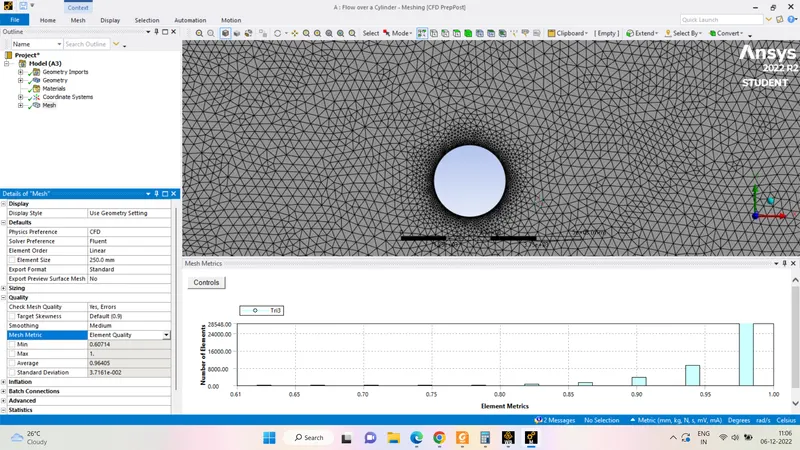
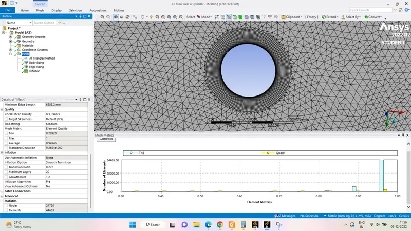
The mesh obtained is of satisfactory with good coverage of area around the cylinder with along with smooth volume transition.The number of mesh elements obtained are of 44663.
3)SETUP:
I am using a computational fluid dynamics (CFD) simulation to model the flow of air through a tunnel. Assuming that the flow is laminar, meaning it is smooth and orderly, with no significant turbulence or mixing of fluid layers. Laminar flow is common at low velocities, such as those below the speed of sound. The material properties and boundary conditions are given which are stated as above.
SOLVER TYPE
Using Pressure-based solver with a steady-state time condition to solve for the pressure and velocity field in the fluid. This approach can provide useful information about the behavior of the fluid flow and the forces acting on the walls of the tunnel.
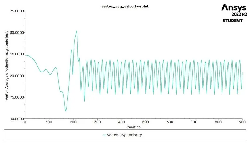
For observations on flow instability we created few reports which gives observation on LIFT, DRAG, also a Monitor point which is created at a distance of 8m in X-direction on backside of the cylinder as VERTEX AVERAGE MONITOR point.
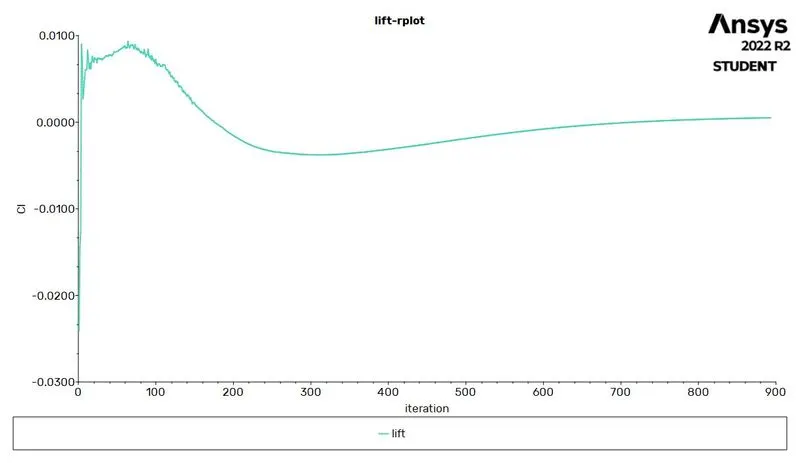
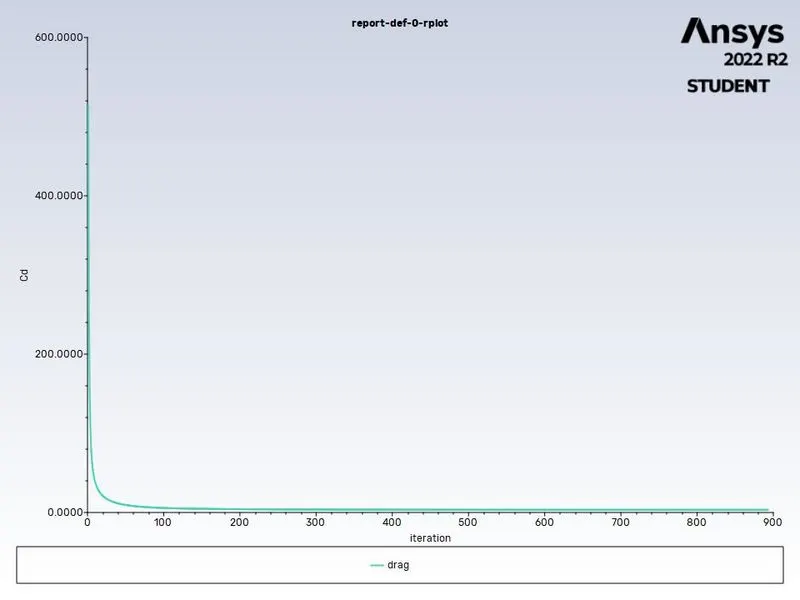
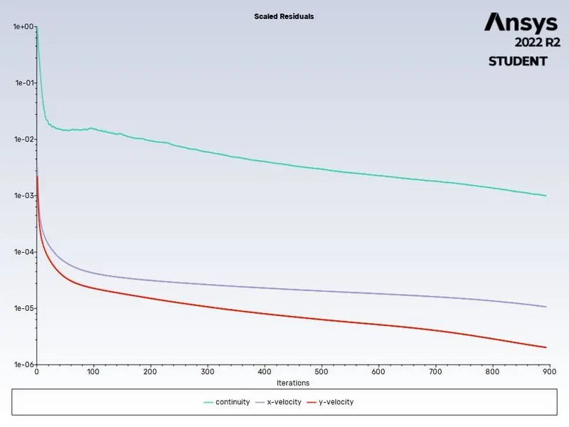
At 893 iteration Solution is converged. And observed the following results.
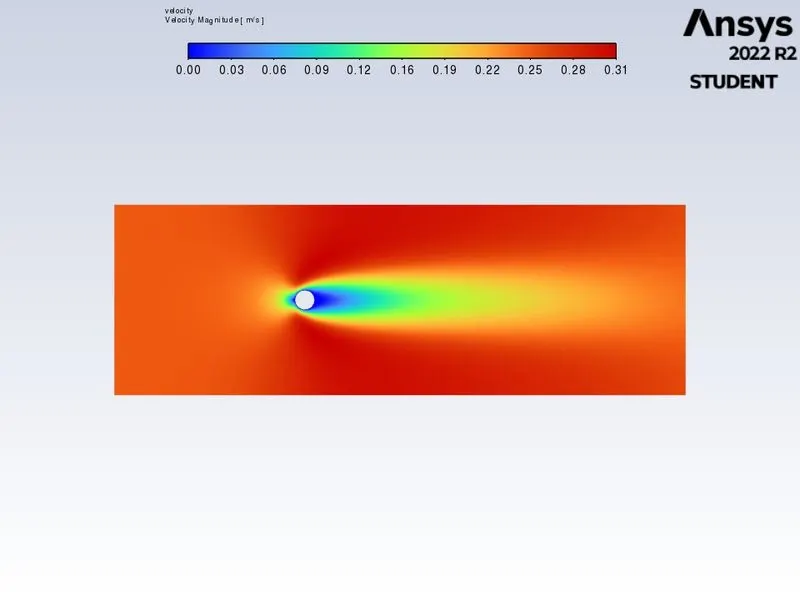
Plots for flow with Re=10 & Velocity=0.25m/sec.
POST-PROCESSING:
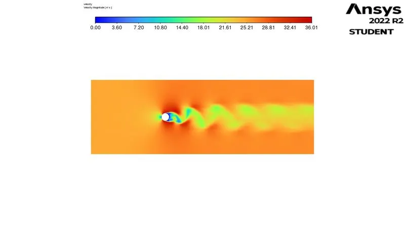
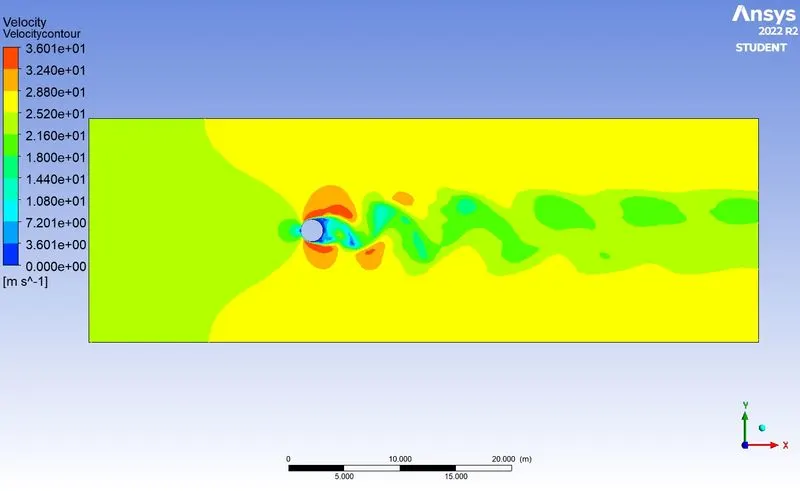
Velocity Contour plot
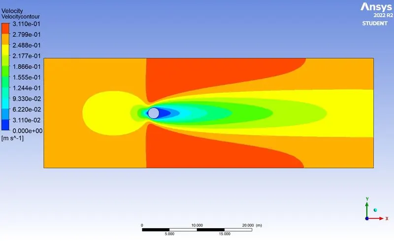
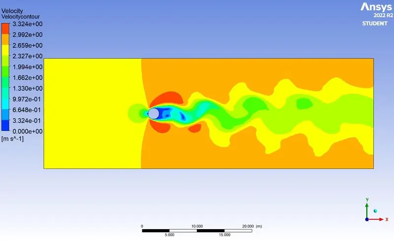
The velocity animation plot is showing the time-varying velocity field around a cylinder in a fluid flow. The wake region is a common feature of flow around cylinders, and it is typically observed behind the cylinder. The wake region is formed when the fluid separates from the surface of the cylinder, resulting in a region of low pressure and low velocity.
In this case, the flow is typically observed to separate from the surface at an angle of approximately 90 degrees, which is why the wake region is often observed behind the cylinder. The formation of the wake region is the result of a pressure gradient across the surface of the cylinder, which causes the fluid to flow more quickly over the top and bottom of the cylinder than it does around the sides. This difference in flow speed results in the separation of the fluid from the surface of the cylinder.
The wake region is typically observed to extend a certain distance behind the cylinder before the flow reattaches to the surface and forms a continuous flow. This distance is known as the wake length.
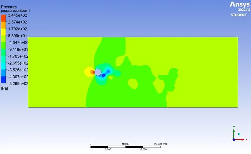
Pressure Contour Plot
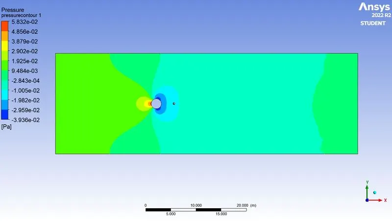
The pressure plot is likely showing the pressure distribution around a cylinder in a fluid flow. When a fluid flows past a cylinder, the velocity of the fluid decreases as it approaches the front of the cylinder and comes to a stop at the surface of the cylinder. This decrease in velocity results in an increase in pressure, which is known as the dynamic pressure. The point at which the velocity is zero and the pressure is at a maximum is called the stagnation point.
At the back of the cylinder, the fluid separates from the surface of the cylinder, resulting in a region of low pressure and low velocity. This is known as the wake region, and it is common for the pressure in this region to be negative, or lower than the ambient pressure of the surrounding fluid. The presence of a negative pressure in the wake region is a sign of flow separation, which can be caused by a variety of factors, including the shape of the cylinder and the angle of attack of the fluid flow.
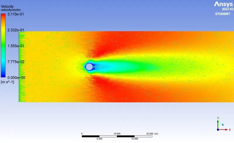
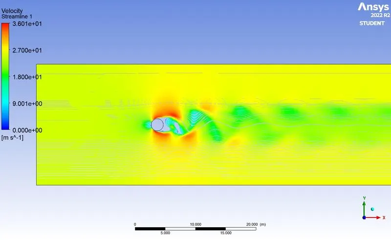
This can be observed from Streamline plot.Streamline plot represents the direction of fluid particle in the form of vectors.
Following are the values of coefficient of lift, coefficient of drag, Vertex velocity,Strohaul Number.
|
Reynolds Number (Re) |
Velocity (m/sec) |
Coefficient of Drag Cd |
Coefficient of Lift Cl |
Vertex average Velocity (m/sec) |
Strohaul Number |
| 10 | 0.25 | 3.3473 | 5.04*10^-4 | 0.1066 |
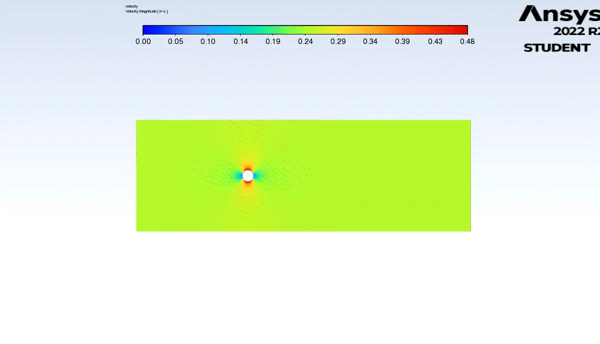
Below animation give us some insights about flow visualization.
For Reynolds Number 100:
Re=(ρVL)/μ
∴V=(Re⋅μ)/ρ⋅L=100*0.05/1*2=2.5m/s.
By only changing the Inlet velocity of the flow with 2.5m/s , repeated the above mentioned procedure.
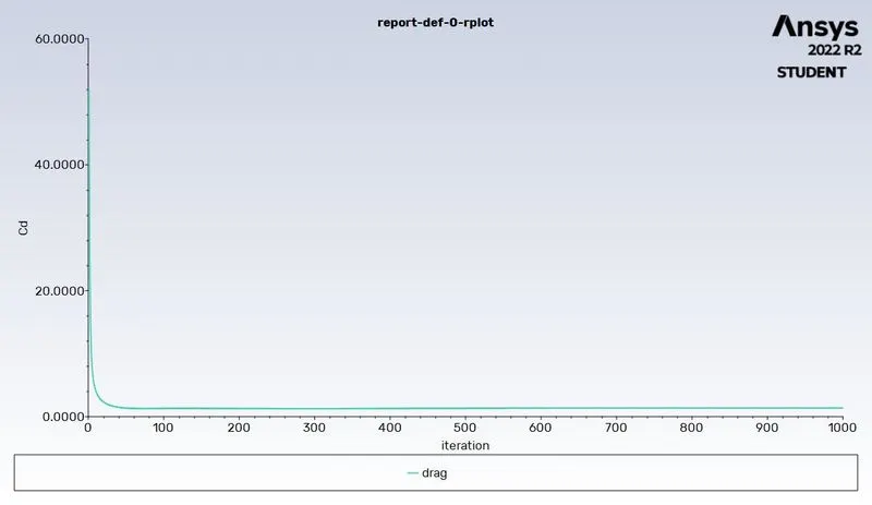
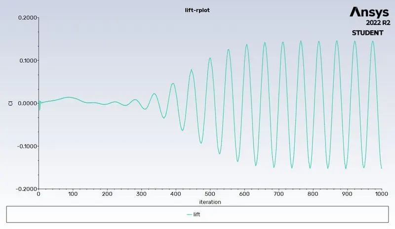
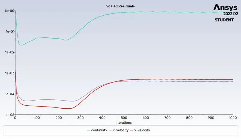
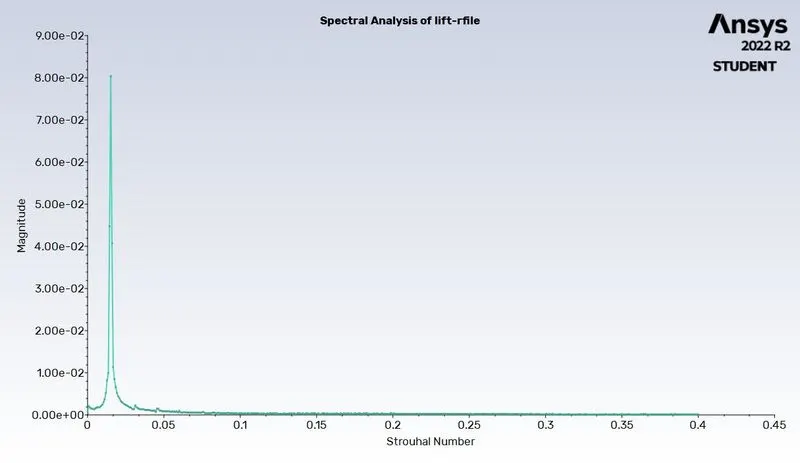
Reynolds numbers above 90 tend to be turbulent, while flows with Reynolds numbers below 90 tend to be laminar.
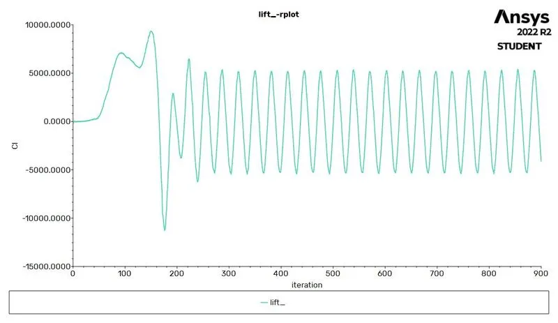
A negative lift in this context would mean that the flow is causing a downward force on the body, which is opposite to the direction of the lift that is typically generated by an aerodynamic object. This may indicate that the flow is unstable, but more information would be needed to make a definitive determination.
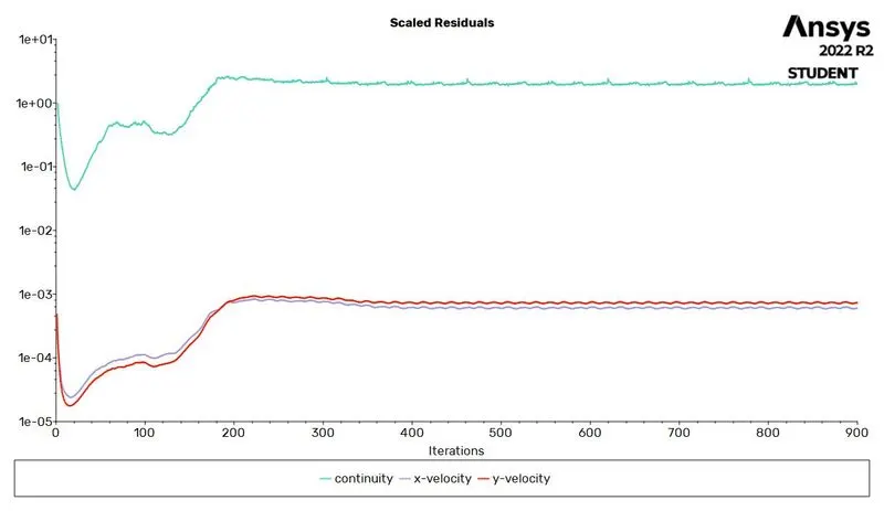
The scaled residuals plot is a measure of the error in the computational fluid dynamics (CFD) simulation. It shows how the residuals, or errors, in the simulation change over time. In general, a decrease in the residuals indicates that the simulation is converging and the results are becoming more accurate. An increase in the residuals, on the other hand, may indicate that the simulation is diverging and the results are becoming less accurate.
In summary, the information provided suggests that the flow is likely to be turbulent and may be unstable, based on the Reynolds number. The scaled residuals plot indicates that the simulation is converging and the results are becoming more accurate.
Following are the values of coefficient of lift, coefficient of drag, Vertex velocity,Strohaul Number.
|
Reynolds Number (Re) |
Velocity (m/sec) |
Coefficient of Drag Cd |
Coefficient of Lift Cl |
Vertex average Velocity (m/sec) |
Strohaul Number |
| 100 | 2.5 | 1.3631 | -0.1511 | 1.0576 | 7.57E-05 |
Pressure Contour Plot
|
Reynolds Number (Re) |
Velocity (m/sec) |
Coefficient of Drag Cd |
Coefficient of Lift Cl |
Vertex average Velocity (m/sec) |
Strohaul Number |
| 1000 | 25 | 1.0965 | -0.4189 | 20.7014 | 2.49E-03 |
When the fluid's Reynolds number is 1000, it may separate from the surface it's flowing over if the pressure gradient is adverse or if there's an obstacle in its path. The fluid's behavior in these situations depends on the flow's specific characteristics.The Reynolds number is inversely proportional to the dynamic viscosity of the fluid, which means that at a lower viscosity (or higher Reynolds number), the fluid will be less affected by viscous forces and may be more prone to separation. This is especially true when the fluid is flowing around a cylinder, where the curved surface and the presence of an obstacle can cause the flow to become unstable and separate from the surface.
For Reynolds Number 1000:
Re=(ρVL)/μ
∴V=(Re⋅μ)/ρ⋅L=10000*0.05/1*2=250m/s.
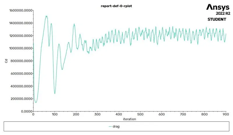
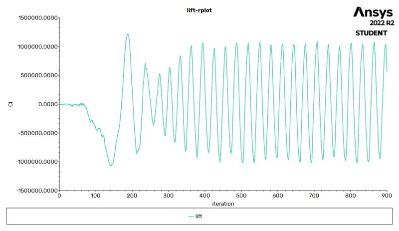
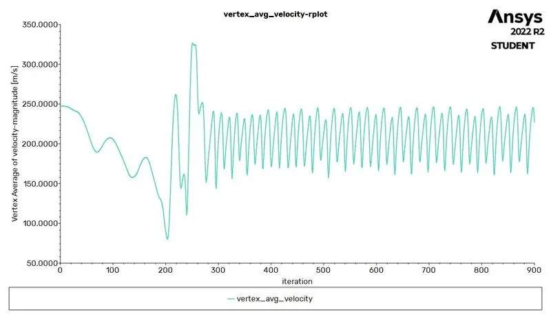
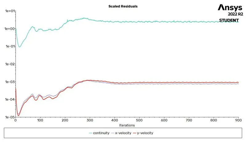
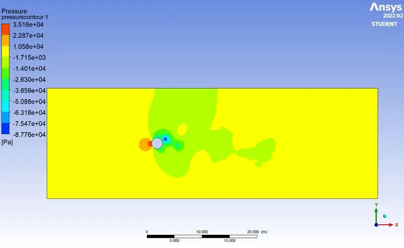
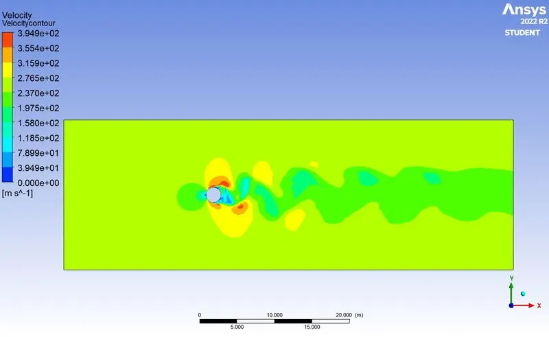
When the fluid's Reynolds number is 10000, it may separate from the surface it's flowing over if the pressure gradient is adverse or if there's an obstacle in its path. The fluid's behavior in these situations depends on the flow's specific characteristics.The Reynolds number is inversely proportional to the dynamic viscosity of the fluid, which means that at a lower viscosity (or higher Reynolds number), the fluid will be less affected by viscous forces and may be more prone to separation. This is especially true when the fluid is flowing around a cylinder, where the curved surface and the presence of an obstacle can cause the flow to become unstable and separate from the surface.
|
Reynolds Number (Re) |
Velocity (m/sec) |
Coefficient of Drag Cd |
Coefficient of Lift Cl |
Vertex average Velocity (m/sec) |
Strohaul Number |
| 10000 | 250 | 0.9987 | -0.7463 | 234.2412 | 1.45E-01 |
CONCLUSION:
If we compare the data in the table, it is seen that as Reynolds number is increasing the coefficient of Drag is decreasing and coefficient of lift is increasing. The above data is compared with Scientific paper mentioned below and from Book FLUID MECHANICS Fundamentals And Applications written byYUNUS A CENGEL and JOHN M CIMBALA https://www.sciencedirect.com/science/article/pii/S0307904X08000243.