Week 3 Challenge : CFD meshing on Turbocharger
Aim: To perform Internal flow analysis on Turbocharger , for that pre-processing stage of CFD is to be performed on it which is geometry cleanup, surface meshing and volumetric meshing has to be done using a suitable algorithm and a cut section view has to be shown for a better understanding Meshing boundaries.
Procedure:
Pre-processing stage of CFD involves the following steps:
1. Importing the geometry of the Turbocharger into the Pre processing (Used ANSA) software.
2. Cleaning up the geometry and ensuring that it is watertight.
3. Creating appropriate boundary conditions for the Turbocharger.
4. Performing a grid independence study to ensure that the results are accurate.
Step 1)The model was checked for geometrical and intersection/penetration errors using the tool CHECKS MANAGER. Found errors of both geometrical and penetration/overlap. Clearing these errors with appropriate actions, which is suitable for internal flow analysis. And closing open ended surfaces to make it as a whole volume.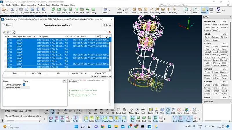
Penetration Of objects.
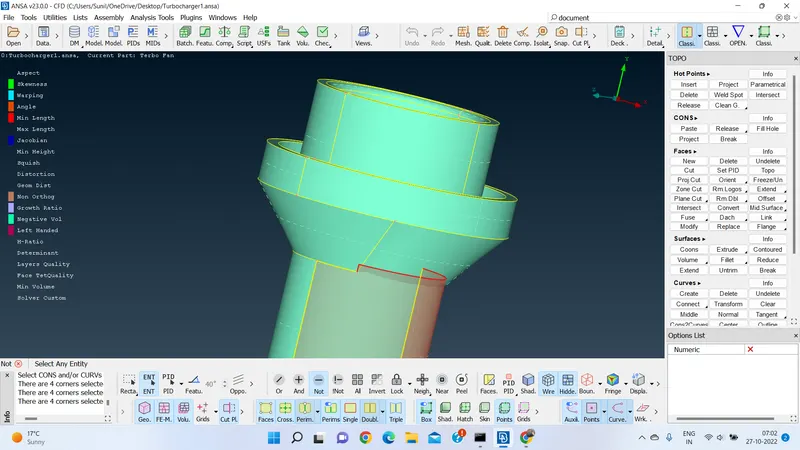
Step 2) Cleared all those errors.
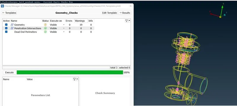
Inorder to make it as a model of watertight one we need to close all the open faces, of which few lead to triple coons formation. As per the analysis point of view those errors may not cause any significant errors to the model. So, as the main criteria is to make the model error free, left the warnings it shown.
Step 3) Before creating boundary conditions Property Identitys are assigned to each and every object using PID tool.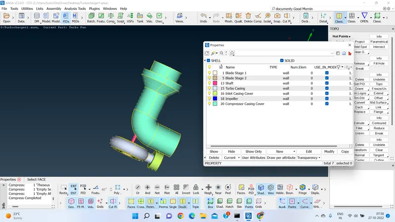
After assigning PIDs to every object/part, used COMPRESS tool for deleting the unnecessary parts of the model to make it easily readable for futher studying of the file.
MESHING:
Here we are going to mesh the model for volumetric analysis. Before that we need to do Surface Meshing. It is done stage wise as per the given specification.
Surface Meshing Specifications:
Mesh element : TRIA
Mesh Size on each part:
- Blade stage-1 = 1 mm
- Blade stage-2 = 1 mm
- Impeller = 2 mm
- Shaft rotor = 1 mm
- Turbo casing = 5 mm
- Compressor casing = 5 mm
- Inlet casing cover = 5 mm
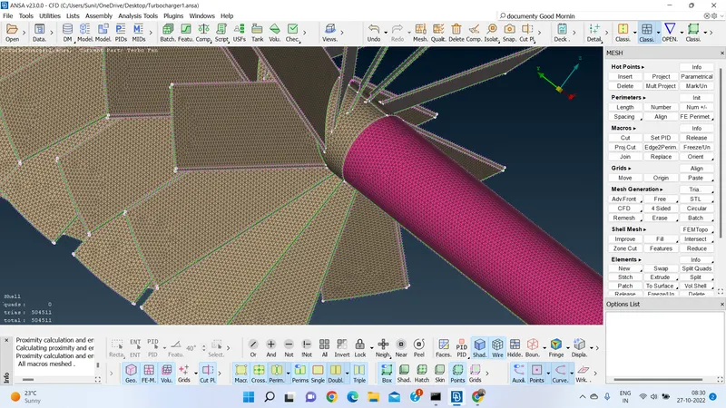
Performed meshing process on Blade stage 1, Blade Stage 2, Shaft rotor as with target length of 1mm with min/max length of element as 0.3/1.3mm
AutoCFD Algorithm < Spacing option in < Parameters tool in Classic Mesh.
CFD>VISIBLE option is used to complete the meshing process.
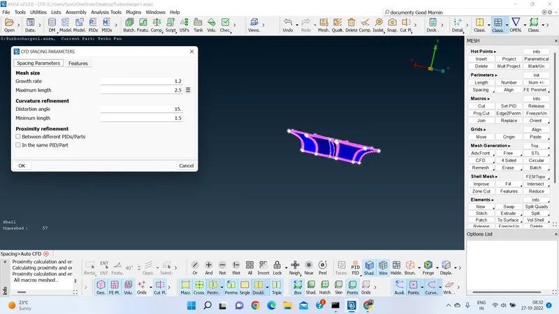
Performed meshing process on Impeller with target length of 2mm with min/max lenth of element as 2.5/1.5mm
AutoCFD Algorithm < Spacing option in < Parameters tool in Classic Mesh.
CFD>VISIBLE option is used to complete the meshing process.
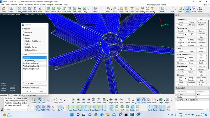
After performing meshing on individual parts,found satisfactory results with formed structued mesh and the growth rate of element is also satisfactory.
But, when I try see the whole model as one, found some Unmeshed objects/parts. these observations found at the place where two or more objects perimeters are coming into contact,there on object with lower tria element length is resulted as UNMESHED
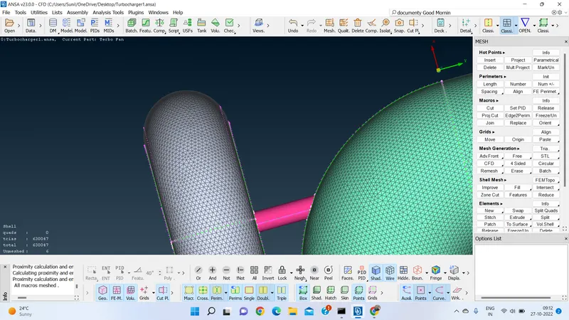
In the above figure, we can observe three different parts connected with each other of different meshing parameter length, we can see on the SHAFT part the missing of Meshing.
As it is incomplete of Meshing, I used FREEZE/UNFREEZE Macros area option in MACROS tool in CLASSIC MESH feature.
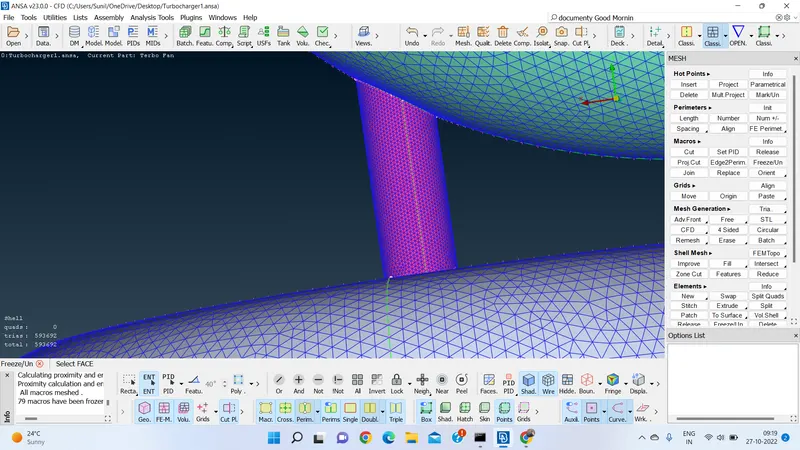
Surface meshing is completed.
VOLUMETRIC MESHING: To do volumetric meshing Surface meshing is the pre-requisite.Volumetric meshing has to be done based on what type of analysis we are going to perform on the given model. As mentioned our main aim/objective is to perform Internal analysis on the given Turbocharger.
For Internal analysis our importance/focus should be on internal meshing the objects.First Unfreeze option is used to openup the model for meshing. For that we need to define the object first. By using VOLUME MESH>VOLUMES>DEFINE. it will show what are volumes present. As said I have choosen only Internal volumes which ever required.
Now from LISTS option, choosen TETRA CFD elment(3d Extension of TRIA element) for volumetric meshing by selecting REMESH option. Performed same procedure for all the volumes chosen.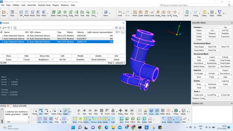
Found satisfactory with the results.
To check for the internal inspection, bisected the model using CUTPLANE >NEW >DEFAULT XY plane option.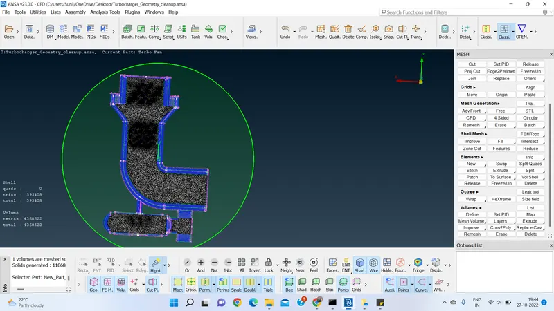
Inspected the results obtained. Only meshing was happened internally.
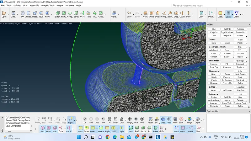
RESULTS:
Geometry cleanup is performed and ensured it with zero errors results shown by CHECKS MANAGER>GEOMETRY CHECK option. Surface Meshing is done succesfully with Tria elements number- 595408. Volumetric Meshing is done successfully with Tetrahedra Elements of number- 4360522.
CONCLUSION: Given model is processed for Pre-processing stage of CFD using ANSA 23.0.0. and results obtained are satisfactory.
LEARNING OUTCOMES
Volumetric Meshing- Importance of selecting the volumes based on the type of analysis.
Proper closure of the object for volumetric consideration.