Week 6 - CHT Analysis on a Graphics card
r CONJUGATE HEAT TRANSFER ANALYSIS ON A GRAPHIC CARD
Conduction is the transfer of energy from the more energetic particles of a substance to the adjacent, less energetic ones as a result of interactions between the particles.
Convection is the mode of heat transfer between a solid surface and the adjacent liquid or gas that is in motion, and it involves the combined effectsof conduction and fluid motion.
Radiation is the energy emitted by matter in the form of electromagnetic waves (or photons) as a result of the changes in
the electronic configurations of the atoms or molecules.
Conjgate Heat Transfer:
Conjugate heat transfer refers to the simultaneous heat transfer through both solid and fluid regions of a system, where the heat transfer between the solid and fluid regions are coupled. This means that the heat transfer within the solid region affects the heat transfer within the fluid region, and vice versa.
Conjugate heat transfer is commonly used in engineering simulations to model the heat transfer in complex systems such as electronic devices, heat exchangers, and engine cooling systems. For example, in the case of an electronic device, the heat generated by the electronic components is conducted through the solid material of the device and then transferred to the surrounding fluid (usually air) by convection. In such cases, the heat transfer through the solid region and fluid region are interdependent and cannot be treated separately.
The simulation of conjugate heat transfer typically involves solving the heat transfer equations in both the solid and fluid regions simultaneously, with appropriate boundary conditions at the interface between the two regions. The heat transfer coefficients and thermal conductivities of both regions need to be accurately determined in order to obtain accurate results.
Steady State:
In steady-state analyses, boundary conditions and loads such as temperature,convection, heat flow,radiation, heat flux, etc. in thermal analyses, must not change with the changing time.
Graphics Card:
A graphics card (also known as a video card or GPU) is an electronic component of a computer that is responsible for rendering images, videos, and other visual information that is displayed on a monitor or screen.
The graphics card is designed to handle complex calculations and processing of visual data that is required for gaming, video editing, 3D modeling, and other demanding applications. It has its own dedicated memory and processor, which allows it to process and display images faster and more efficiently than the CPU (central processing unit) of the computer.
The graphics card is connected to the motherboard of the computer and typically has its own cooling system, which helps to dissipate the heat generated by the GPU during intensive tasks. Different types of graphics cards have different capabilities, and some are more powerful than others. It is an essential component for modern computer systems, especially for tasks that require high-quality graphics and video rendering.
Components Of a Graphic Card Unit:
Here are the components of a graphics card listed:
- GPU (Graphics Processing Unit)
- Video memory (VRAM)
- Cooling system (e.g. fans or heat sink or Integrated Heat Spreader or Extended Surface Area In the form of FINS)
- Power delivery system (e.g. power connectors and voltage regulation)
- Display outputs (e.g. HDMI, DisplayPort, DVI)
- Optional features (e.g. RGB lighting, specialized ports, custom overclocking software)
- PCB(Printed Circuit Board)
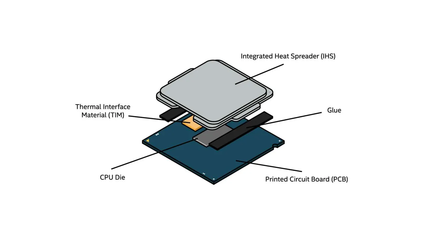
All the above components are attached to the PCB where the Electricity conducting material is etched on a insulating material which have a property of non conducting to heat and electricity to other components.
While working the graphics card (GPU) generates heat as a byproduct of its operation, especially during demanding tasks such as gaming or rendering high-resolution videos. The heat generated by the graphics card can cause damage to the components and reduce the lifespan of the GPU if not properly managed. Some common causes of heat generation in a graphics card include:
-
High workload: The more work the GPU is doing, the more heat it generates. Applications that use 3D graphics, virtual reality, or video encoding/decoding put a heavy load on the graphics card, causing it to heat up quickly.
-
Overclocking: Overclocking is the process of increasing the clock speed of the GPU, which can improve its performance but also increases its heat output. Overclocking a graphics card without proper cooling can cause it to overheat and damage the components.
-
Poor ventilation: Graphics cards need proper ventilation to cool down, and inadequate ventilation can cause the GPU to overheat. If the graphics card is installed in a cramped space or the computer case has poor ventilation, the heat generated by the GPU can get trapped, causing the GPU to overheat.
-
Dust buildup: Over time, dust can accumulate inside the graphics card's cooling system, obstructing the airflow and causing the GPU to overheat. Regular cleaning of the graphics card can help prevent this issue.
-
Aging components: As the graphics card ages, the thermal paste that helps transfer heat from the GPU to the cooling system can become less effective, causing the GPU to overheat. In some cases, the cooling system itself may become less effective over time due to wear and tear.
Active and passive cooling are two common methods used to cool electronic components, such as CPUs and graphics cards, that generate heat during operation.
Active cooling: Uses a fan or other mechanical device to circulate air over the heat-generating component and dissipate the heat. The fan may be attached directly to the component, or it may be part of a larger cooling system that includes heat sinks and other components. Active cooling is typically more effective than passive cooling, as it can provide a higher rate of airflow and cooling performance. However, it can also generate more noise and consume more power.
Passive cooling: Passive cooling does not use any mechanical components and relies on natural convection to dissipate heat. Passive cooling typically involves using a heat sink, which is a metal plate or structure that is designed to absorb and transfer heat away from the component. The heat sink may have fins or other features that increase its surface area and improve its cooling performance. Passive cooling is generally quieter and more energy-efficient than active cooling, but it may not be as effective in dissipating large amounts of heat.
Heat Pipes are also a prominent device which is in use in cooling of electronic components.A heat pipe is a heat transfer device that employs phase transition to transfer heat between two solid interfaces.
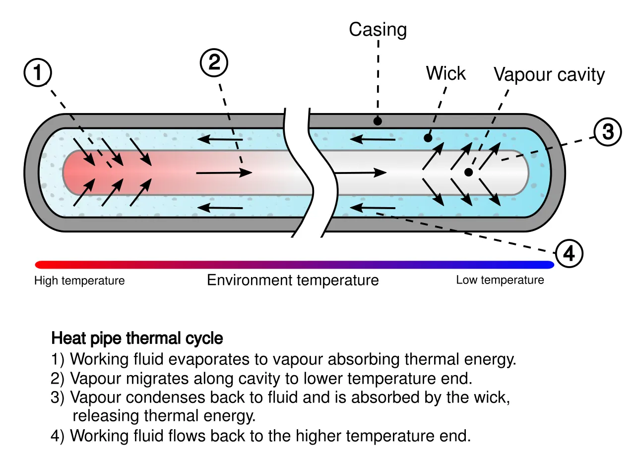
At the hot interface of a heat pipe, a volatile liquid in contact with a thermally conductive solid surface turns into a vapor by absorbing heat from that surface. The vapor then travels along the heat pipe to the cold interface and condenses back into a liquid, releasing the latent heat. The liquid then returns to the hot interface through either capillary action, centrifugal force, or gravity and the cycle repeats.
In some cases, both active and passive cooling methods may be used together to provide a balanced approach to cooling. For example, a graphics card may have a combination of fans and heat sinks to provide effective cooling while minimizing noise and power consumption. The choice of cooling method depends on the specific requirements of the component, such as its power consumption, heat generation, and noise level.
AIM:
To Perform a steady-state conjugate heat transfer analysis on a model of a graphics card. By using appropriate materials of choice for the simulation. Make sure to properly define the correct solid and fluid zones.
Run the simulation for best possible mesh with combination of coarse and refined mesh in different regions. Explain the reason for choosing the particular mesh settings.
Objectives:
- Run the simulation by varying the velocity from 1m/sec to 5m/sec for at least 3 velocities and discuss the results.
- Find out the maximum temperature and heat transfer coefficient attained by the processor.
- Prove that the simulation has achieved convergence with appropriate images and plots.
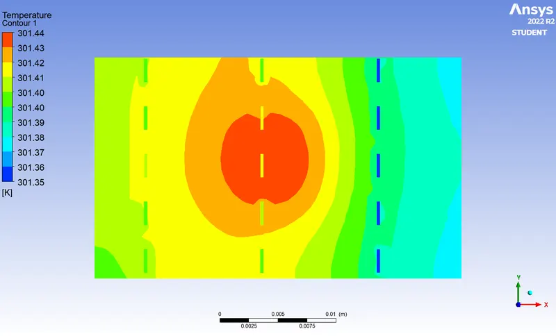
- Identify potential hotspots on the model.
GRAPHIC CARD SETUP:
The following assumptions have been made based on the given statement that Material Specifications of Graphics cards are user discretion. Please note that these assumptions are relevant only for the purpose of basic analysis and are strictly limited to this particular problem.
Here I made assumptions only for few components, those are mentioned below.
Materials Choosen for Graphics card:
- Processor: Silicon
- Fins :Aluminium
- Printed Circuit Board(PCB): Polysterene
Properties of Materials:
|
Name of the Component |
Name of the Material |
Density kg/m^3 |
Thermal Conductivity K W/m K |
Specific Heat c J/ kg K |
| Processor | Silicon | 2330 | 153 | 703 |
| Fins | Aluminium | 2707 | 204.2 | 896 |
| PCB Board | Polysterene | 55 | 0.027 | 1210 |
Understanding the Physics of Setup:
To understand the physics behind the setup, it's important to note that heat is predominantly generated in the processor of a GPU, where all calculations and interactions with other components take place. The graphics card's processor consumes electrical energy to perform its calculations and operations. As a result, some of this energy is converted to heat energy, which is emitted by the graphics card as thermal energy. This is due to the resistance within the graphics card that opposes the flow of electrical current and causes some of the electrical energy to be lost as heat energy, which is an undesirable outcome.
Assumptions for Heat dissipation from Graphic Card Processor Q=1W.
A=Area of the Processor=8mm*8mm=64mm^2.
Volume of the Processor=8mm*8mm*1mm=64mm^3
=64*10^-9m^3
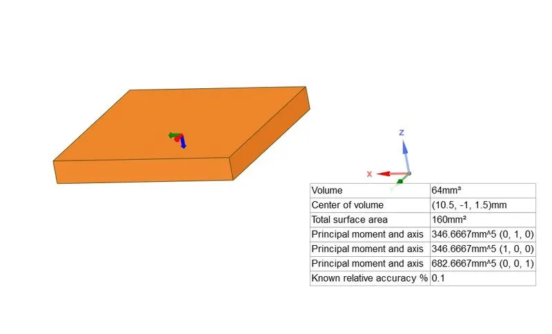
We need to calaculate for Volumetric Heat generation,
q=Q/V
q=1/64*10^*9=15625000W/m^3
The rate of heat conduction through a plane layer is proportional to the temperature difference across the layer and the heat transfer area but is inversely proportional to the thickness of the layer.
Rate of heat conduction ∝(Area)(Temperature difference)/ Thickness
Qcond=-kA(dT/dx)
From this equation we can say that Heat Transfer through conduction is directly proportional to the temperature gradient and to the area, and inversely proportional to the Thickness.
We know that heat transfer through the wall is in the normal direction to the wall surface, and no significant heat transfer takes place in the wall in other directions. The rate of heat transfer from a surface at a temperature Ts to the surrounding
medium at T∞ is given by Newton’s law of cooling as,
Qconv = h As(Ts - T∞)
where As is the heat transfer surface area,
h is the convection heat transfer coefficient.
When the temperatures Ts and T∞ are fixed by design considerations, as is often the case, there are two ways to increase the rate of heattransfer: to increase the convection heat transfer coefficient h or to increasethe surface area As. Increasing h may require the installation of a pump or fan.
From both Conduction and covection equation, we can say that by increasing the surfae area we can facilitate for mor heat transferat faster rate. So we placed a EXTENDED SURFACE AREA in the form of FIN PLATE. Even for further improvement of heat transfer here we employed the FORCED CONVECTION mode of heat transfer which is an ACTIVE MEDIUM of cooling method by using a FAN(Fan position/placement is not shown in the geometry).
So here we need to observe for temperature distribution from processor to fin plate and the heat transfer coefficient of it.
PROCEDURE:
To simulate the flow and have a better visual understanding of the simulation i used a commercial CFD code software ANSYS FLUENT which have great features for these kind of problems in the industry.
Inorder to simulate the flow, the problem definition has to setup in the flow of CFD process which is ,
1)Geometry Cleanup/Pre-Processing
2)Meshing
3)Setup & Solution
4)Post Processing.
1)Geometry Cleanup/Pre-Processing:
Model of GPU unit is provided in the form of STEP file. Used SPACECLAIM tool for Pre-Processing the model like for correcting the geometrical errors.Checked for errors NO errors found in the geometry. An Enclosure is created around the GPU as the analysis is EXTERNAL HEAT TRANSFER ANALYSIS, so flow has to be simulated in a control environment and has to give some Boundaries for calculations.
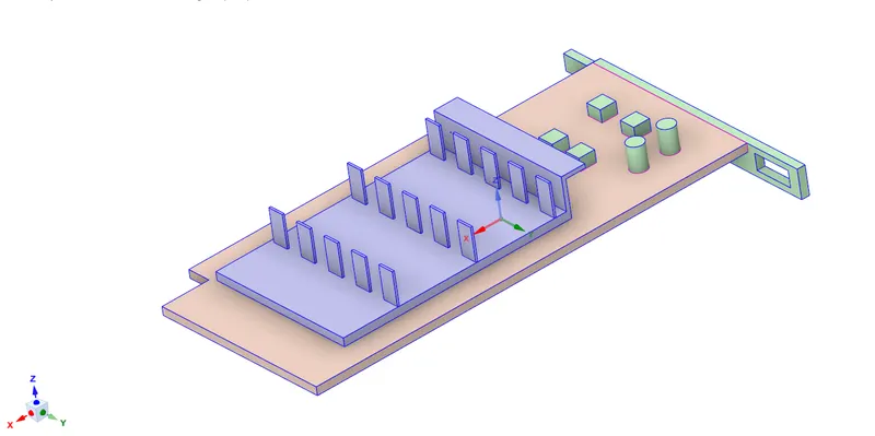
PCB(Printed Circuit Board): Processor
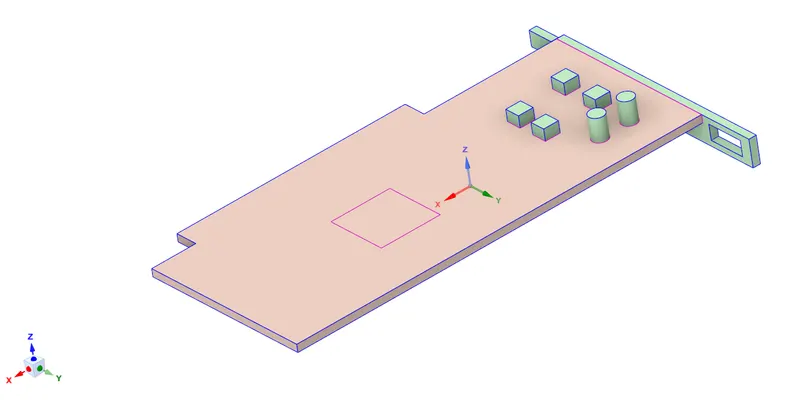
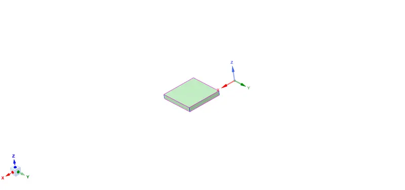
Fin Plate(Heat Sink):
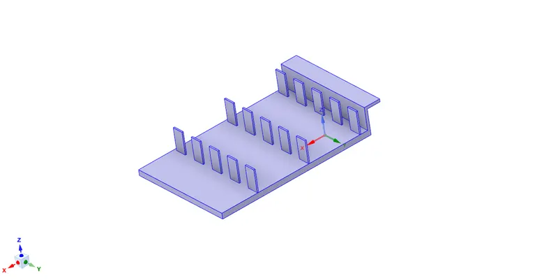
To allow information sharing between nodes of elements SHARE TOPOLOGY has been enabled. So that information between node element is possible.
Sharing topology in ANSYS Fluent can provide benefits such as improved accuracy, reduced computational resources, enhanced flexibility, improved convergence, and more realistic simulation results. Overall, it helps improve the efficiency and accuracy of simulations
MESHING:
Meshing is done with default option in ANSYS.With 8mm Coarse mesh.Following were the results obtained.
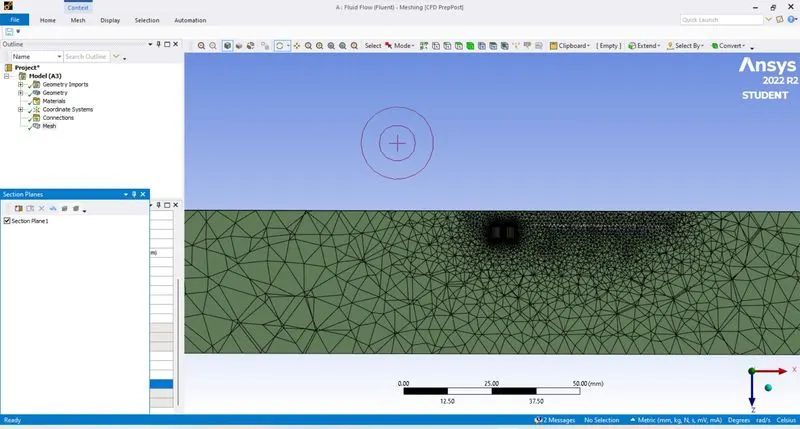
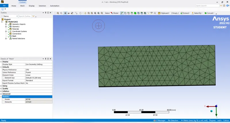
Elements=227429
Nodes=40748
Element Quality is fine.
Naming Convention has been given for convenience of identifying the parts/flow directions.
Setup & Solution:
As mentioned above material specifications has to be specified in MATERIAL MANAGER in Fluent tab.
By using Cellzone condition option we need specify which is the fluid domain,which is the solid domain helps in identifying for further processes.
Solver Type: Pressure Based Solver
Viscous Model:k-omega turbulence -SST model
k-omega turbulence model is a reliable choice for this CHT analysis of low Reynolds Number. It has been chosen due to its ability to accurately predict near-wall behavior and heat transfer characteristics. The model is based on the RANS equations and includes a wall function to account for the near-wall turbulence. The specific dissipation rate equation is used to model the transfer of thermal energy through the turbulent eddies, allowing for accurate prediction of heat transfer.
The SST k-ω turbulence model [Menter 1993] is a two-equation eddy-viscosity model which has become very popular. The shear stress transport (SST) formulation combines the best of two worlds. The use of a k-ω formulation in the inner parts of the boundary layer makes the model directly usable all the way down to the wall through the viscous sub-layer, hence the SST k-ω model can be used as a Low-Re turbulence model without any extra damping functions. The SST formulation also switches to a k-ε behaviour in the free-stream and thereby avoids the common k-ω problem that the model is too sensitive to the inlet free-stream turbulence properties. Authors who use the SST k-ω model often merit it for its good behaviour in adverse pressure gradients and separating flow. The SST k-ω model does produce a bit too large turbulence levels in regions with large normal strain, like stagnation regions and regions with strong acceleration. This tendency is much less pronounced than with a normal k-ε model though.
Boundary Condition:
Inlet :Velocity Inlet with varying velocities 1,3,5 m/sec.
Outlet :Pressure Outlet(0 Gauge Pressure)
For Processor Heat generating boundary condition has been given by selecting it as Source Term which generate heat as 15625000W/m^3.
Report Definition: Report definitions has been created for
- Heat Transfer Coefficient,
- Maximum Temperature of Processor.
Initialization: Hybrid Initialization
Number of Iterations: 150
Following were the observations drawn from the simulation.
Scaled residuals Plot for 8mm Mesh and 1mm body size mesh
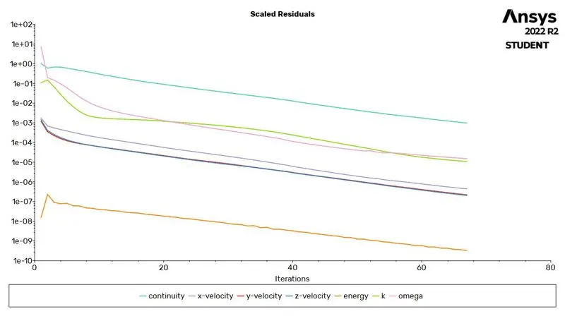
From the above graph we can see some variables are converged or reached a value of 10^-6 which states that the error percentage is less.
Maximum Temperature Of Processor:
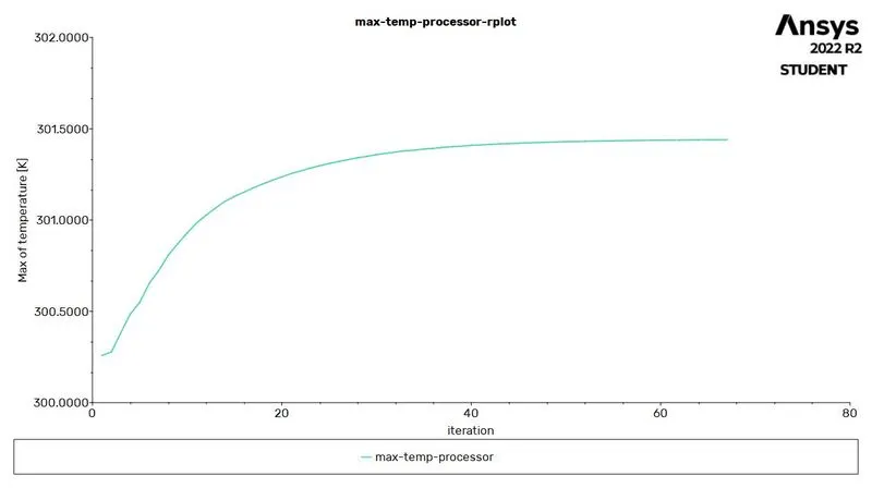
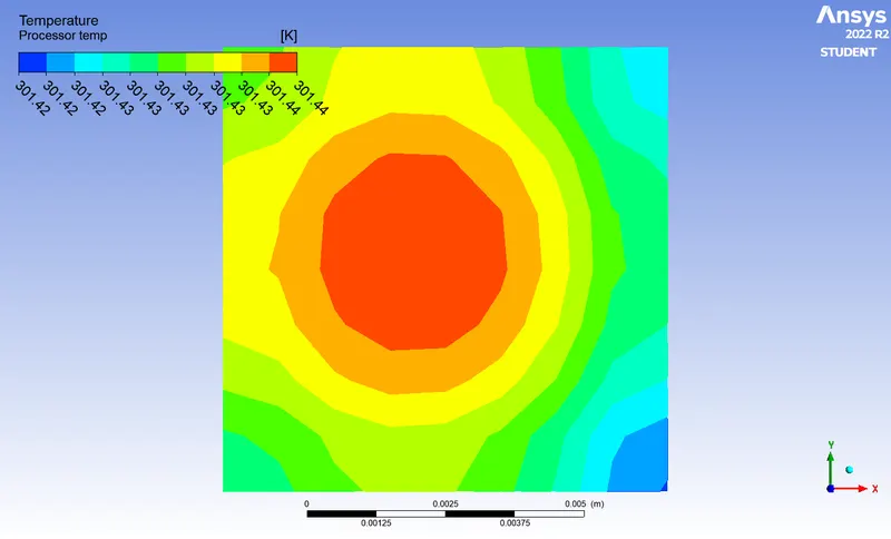
From the plot we can see that after reaching a certain point there is no variation in temperature. States that it reached a stable condition to 301.44K.
Heat Transfer Coefficient:
Here I used forced convection method of cooling by allowing fluid(Air) medium to flow around and on the graphic card. So we need to calculate the Surface Heat tansfer Coefficient which gives us a measure of amount of emergy transfer took place. Here we are looking for the amount of thermal energy which is removed from Processor where it is in contact with air.
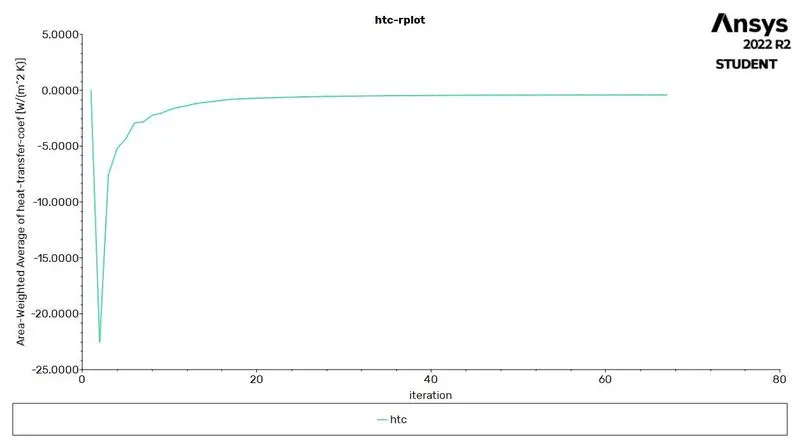
Heat transfer Coefficient for this flow with velocity 1m/sec is -0.41782W m^-2 K^-1. The Negative sign here indicates that reduction/removal.
Here are the pictures for the above simulation.
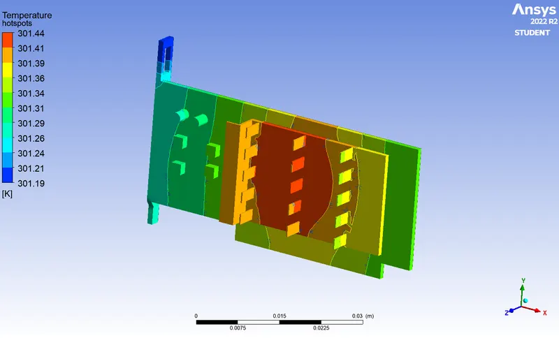
Hotspots on Fin and Processor
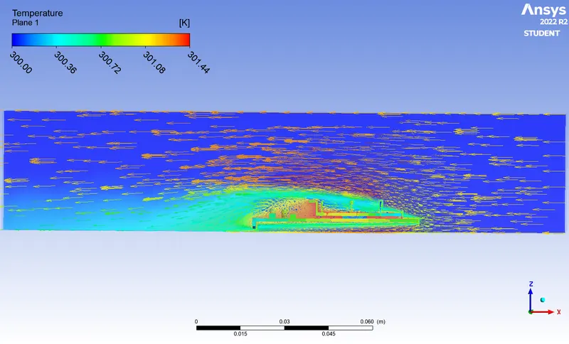
From the Below picture we can say that Flow direction, and action of fluid flow on the graphic card.
Hotspot On Processor:
Again the simulation is carried out with three different velocities. Following were the results.
|
Velocity m/sec |
Maximum Temperature of Processor Kelvin |
Surface Heat Transfer Coefficient W /m^2 K^1 |
| 1 | 301.44 | -0.41782 |
| 3 | 300.7 | -1.5546 |
| 5 | 300.5 | -4.5121 |
CONCLUSION:
Based on the simulation results, it can be concluded that an increase in fluid flow velocity is accompanied by a rise in temperature. However, when the flow rate is at 5m/sec, the surface heat transfer coefficient is observed to be high. This is a favorable outcome for the simulation.
References:
CPU Cooler: Liquid Cooling Vs. Air Cooling - Intel
Heat And Mass Transfer Data Book- C.PKOTHANDARAMAN, S.SUBRAMANYAM-New Age International Publishers
Heat And Mass Transfer- YUNUS A.CENGEL | AFSHIN J.GHAJAR