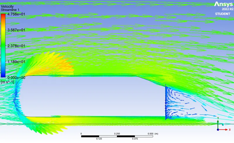
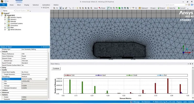
Week 3 - External flow simulation over an Ahmed body.
EXTERNAL FLOW ANALYSIS OVER AHMED BODY
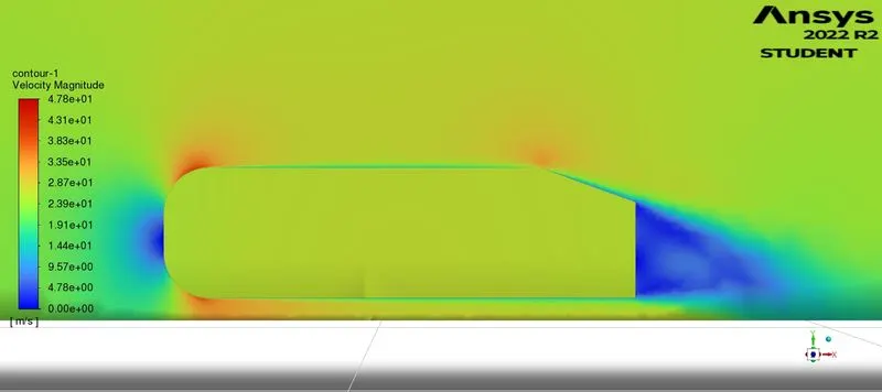
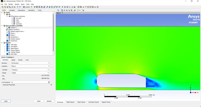
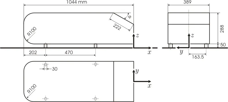
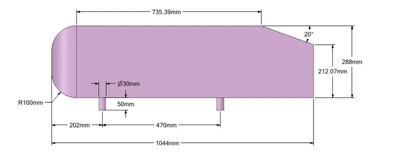
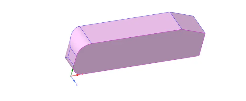
In the study of aerodynamics on an automobile, we are using a shape called the Ahmed body with a rear slant angle of 20 degrees to investigate certain aspects of the flow, such as the drag and lift forces, the separation of flow, and the forces in the wake region. We are also using this shape to validate the measured data.
AHMED BODY:
INTRODUCTION:
The Ahmed body is a geometrical shape that is often used in CFD (Computational Fluid Dynamics) simulations to study the flow of fluids around a vehicle. It was first proposed by Ahmed and his colleagues in the 1980s as a simple and reliable benchmark geometry for evaluating the accuracy of CFD codes.
The Ahmed body has a streamlined shape with a flat base and a sloping rear, which makes it a good approximation of a simplified vehicle. It is commonly used to study the flow around cars, trucks, and other vehicles, as well as to investigate the effect of various design parameters on the aerodynamic performance of the vehicle.
The Ahmed body has several features that make it a popular choice for CFD simulations:
-
Simple geometry: The Ahmed body has a simple geometry with only a few flat surfaces, which makes it easy to model and mesh.
-
Symmetry: The Ahmed body has a symmetry plane running through its center, which allows for reduced-order simulations using only one-half of the geometry.
-
Realistic flow conditions: The Ahmed body generates realistic flow conditions that are similar to those found in real-world vehicles, such as separation and reattachment of the flow on the sloping rear.
-
Widely available experimental data: There is a large body of experimental data available for the Ahmed body, which allows for validation of CFD simulations.
Overall, the Ahmed body is a useful tool for studying the flow of fluids around a vehicle and for evaluating the performance of CFD codes.
"Our main Intention is to study the flow of fluid and the effectscaused by it around the vehicle."
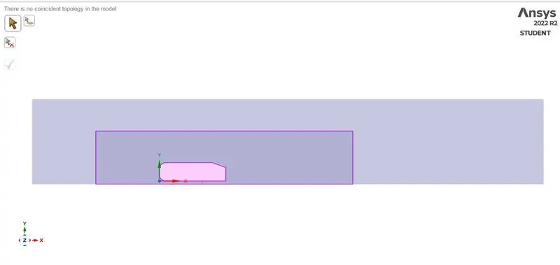
- In this simulation, we are only considering the external flow around the Ahmed body and excluding the internal part of the body, as it is not necessary to perform calculations there. The simulation will be performed within an enclosure that surrounds the body, which will act as the control volume for the flow.
- The Ahmed body that we are using for studying has a rear slant angle of 20 degrees.
- Assuming the flow medium is AIR with Inlet flow velocity (25 m/s) . The density of air at standard temperature and pressure (STP) is 1.225 kg/m^3, and the dynamic viscosity of air at STP is 1.81x10^-5 Ns/m^2. The thermal conductivity of air is 0.026 W/mK and no pressure gradient at the outlet.
- Assuming the body and the tunnel for measuring are both insulated, there is no heat transfer between them, and no heat exchange occurs.
- NoSlip condition over the Ahmed body .
-
To calculate the Mach number for the flow over the Ahmed body, you will need to know the flow velocity and the properties of the flow medium.
Assuming that the flow velocity is 25 m/s and the flow medium is air at standard temperature and pressure (STP), the Mach number can be calculated using the following equation:
Mach = V/C
where V is the flow velocity, and C is the speed of sound in the flow medium. The speed of sound in air at STP is approximately 343 m/s.
The values for V and C, we get:
Mach = 25/343 = 0.0726
This means that the flow over the Ahmed body has a Mach number of approximately 0.0726, which indicates that the flow is Subsonic (i.e. the flow velocity is less than the speed of sound. This means that the flow is not fast enough to generate a shock wave or compressibility effects, and the flow can be treated as incompressible.)
If Mach Number is >0.33 we may need to consider the compressibility effects of the fluid. Here it is less.So, we are not considering the compressibility effects of fluids.
| TOP | BOTTOM | LEFT HAND SIDE | RIGHT HAND SIDE | REAR | FRONT |
| 1000 | 0 | 500 | 0 | 5000 | 2000 |

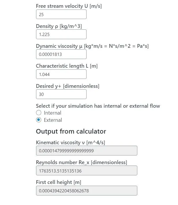
The Y+ value is a dimensionless parameter that is used to calculate the first layer thickness in computational fluid dynamics (CFD) simulations. It is defined as the ratio of the first layer thickness to the viscous length scale, which is a measure of the distance over which the viscous forces become dominant.
The Y+ value is typically in the range of 30-300 for fully turbulent flows, with a value of around 100 being commonly used as a reference value. The Y+ value is dependent on the flow velocity, the flow medium, the viscosity of the flow medium, and the roughness of the surface.
To decide on the appropriate Y+ value for a given flow, you can consider the following factors:
-
Convergence of the solution: A higher Y+ value may result in a more accurate solution, but it may also require a finer mesh and more computational resources.
-
Accuracy requirements: The Y+ value should be chosen based on the accuracy requirements of the simulation. If a higher accuracy is required, a higher Y+ value may be needed.
-
Computational resources: The Y+ value should also be chosen based on the available computational resources. If the simulation is computationally intensive, a lower Y+ value may be needed to reduce the computational burden.
-
Comparison with experimental data: If experimental data is available for the flow, the Y+ value should be chosen such that the simulated results are in good agreement with the experimental data.