Week 8 - Simulating Cyclone separator with Discrete Phase Modelling
TO PERFORM ANALYSIS ON A CYCLONE SEPARATOR AND CALCULATE THE SEPARATION EFFICIENCY AND PRESSURE DROP.
CYCLONE SEPARATOR:
Introduction:
A cyclone separator is a type of mechanical separator that uses centrifugal force to separate particles from a gas stream. It is typically used to remove particles from an air stream, but can also be used to separate particles from other gases.
A cyclone separator consists of a cylindrical body and a conical shape at the top, called the vortex finder, which creates a spiral flow pattern inside the separator. The inlet gas enters the separator at the top and is then spun around the wall of the cyclone at high speeds, causing the heavier particles to be thrown out to the wall of the separator. These particles then fall to the bottom of the separator and are removed through a discharge outlet, while the cleaner gas is discharged at the top, through the vortex finder.
Cyclone separators are widely used in various industrial processes such as cement, power plants and mineral processing as a method for particle separation, dust collection and particle filtration. They are simple, reliable, low-cost, low maintenance, and don't require any consumable filters.
Cyclones are versatile devices, with variety of geometries, size and construction materials, depending on the application and dust/particle characteristics.
Discrete phase modeling (DPM) is a method used in computational fluid dynamics (CFD) to simulate the behavior of solid particles or droplets suspended in a fluid. It is used to model multiphase flows, where the fluid and particles are treated as distinct entities. The fluid is modeled using the usual fluid dynamic equations and the motion of the particles is modeled using the Newton's laws of motion. DPM treats each particle as a separate entity, with its own position, velocity, and other properties, and thus it's called discrete phase.
DPM simulations can be used to model a wide range of multiphase flows, including particle-laden flows in cyclone separators, spray systems, and dust collection systems. It is also used to study particle-wall interactions, and the behavior of particles in turbulent flows. DPM provides detailed information about the flow and particle behavior in multiphase systems, such as the particle size distributions, residence time, particle trajectory and can be used to predict the efficiency of different systems.
In Discrete Phase Modeling (DPM) simulations, there are two main ways to model the interaction between the particles and the fluid: single-phase DPM and coupled DPM.
Single-phase DPM: In single-phase DPM, the particles are treated as a separate phase and their motion is modeled using the Newton's laws of motion. The fluid phase, however, is modeled using the usual fluid dynamic equations, and the interaction between the fluid and the particles is modeled using a drag model. Single-phase DPM simulations are relatively simpler and computationally less expensive, but they may not always provide an accurate representation of the flow and particle behavior.
Coupled DPM: In coupled DPM, both the particles and the fluid phase are modeled using the full set of fluid dynamic equations. The interactions between the fluid and the particles are treated as mutual interactions, and both phases are solved together. This provides a more accurate representation of the flow and particle behavior, but it is computationally more expensive and requires a more robust solver.
It's worth noting that, coupled DPM is more accurate than single-phase DPM and provides more detailed information about the flow and particle behavior. However, it can also be more computationally demanding. Therefore, it's important to choose the appropriate model depending on the specific problem and the available computational resources.
There are several empirical models that can be used to calculate the efficiency of a cyclone separator. Here are four commonly used models:
-
The Iozia and Leith Model: This is one of the most well-known empirical models for calculating the efficiency of a cyclone separator. It uses the physical dimensions of the cyclone and the characteristics of the gas stream to calculate the expected efficiency of the separator.
-
The Beta-ratio method: This method is an alternative to the Iozia and Leith model, it uses statistical analysis of experimental data to determine the slope parameter of the differential efficiency curve and uses the cut-off diameter to estimate the efficiency.
-
The Stairmand Model: This model uses the geometry of the cyclone, the fluid properties and the inlet conditions to determine the efficiency of the cyclone. The model is based on the balance of forces acting on the particles and the particles motion inside the cyclone
-
The Wen and Yu Model: This model is based on the observation of the flow behavior inside the cyclone and the particle motion. It uses the inlet conditions, geometrical properties and fluid properties to estimate the efficiency.
It's worth noting that, each of these models have their own assumptions, limitations and parameters to consider. Therefore it's important to choose the appropriate model for the specific problem and to have enough experimental data to provide the best approximation.
In this project, I used the ANSYS Fluent commercial CFD software for simulating the flow and particle behavior in the cyclone separator. ANSYS Fluent is a powerful and widely-used CFD tool that provides advanced modeling capabilities and a wide range of options for setting up and solving complex fluid flow problems.
ANSYS Fluent is particularly well-suited for this application because it offers a wide range of features for modeling the multiphase flow and particle behavior inside the cyclone separator, including models for particle-laden flows, particle-wall interactions, and particle tracking. Additionally, it's ability to handle complex geometries and it's integration with pre-processing and post-processing software makes it easier to set-up and analyze the simulation.
The tool also provides various options to model the turbulent flow, heat transfer and chemical reactions which are of great importance in the case of cyclone separator as they can greatly affect the separation efficiency.
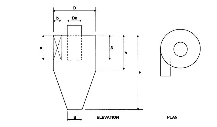
| GEOMETRY BASED ON | a/D | b/D | De/D | S/D | h/D | H/D | B/D |
| STAIRMAND MODEL | 0.5 | 0.25 | 0.5 | 0.63 | 2 | 4 | 0.25 |
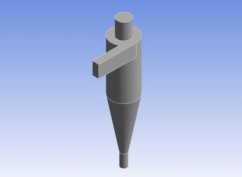
MESHING:
To ensure accurate and efficient computation, in this project, a Cartesian meshing technique with 5mm element size was employed for the complex geometry that contains sharp edges and internal cavities. The Hex dominant elements were used as the base size to capture the intricate features of the geometry. This meshing method allowed for detailed representation of the sharp edges and internal cavities and ensured proper resolution of the flow phenomena inside the cyclone separator.
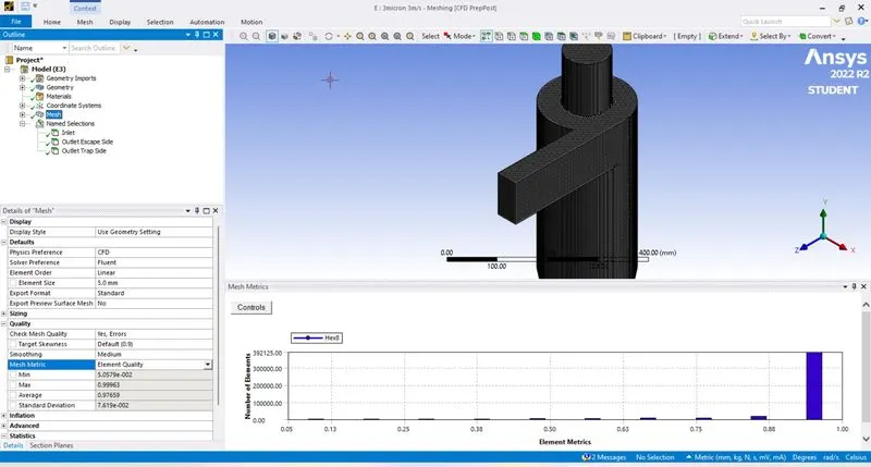
Number of mesh elements were 4.27lakhs. Geometry is captured properly.
SETUP:
In this simulation, the fluid medium is air and the dispersion medium consists of anthracite particles with a diameter of 1 μm, 3 μm, and 5 μm. These particles are injected into the flow of air. No energy equation is used in the simulation, only the equations of fluid dynamics and particle dynamics are solved. This allows for an analysis of the performance of the cyclone separator under different particle size conditions without accounting for the energy exchange between the phases.
- Solver Type: Pressure Based
- Time: Steady
- Gravity: -9.81 m/s2 (in –Y direction)
- Boundary conditions:
Inlet :Velocity inlet
Outlet :Pressure Outflow
Cyclone wall Function: Enhanced wall function
- Viscous Model:
Turbulence Reynolds stress model (RSM)
RNG k-Epsilon - Discretization:
Pressure-velocity coupling :COUPLED
Momentum :2nd order upwind
Turbulence kinetic energy :2nd order upwind
Turbulence dissipation rate: 2nd order upwind
Reynolds stresses :2nd order upwind - Discrete phase modelling:
Particels : Anthracite of varying sizes.
These particles are injected normal to the inlet direction.
Assumption :Spherical particle
Inlet= Reflect
Outlet TopSide=Escape
Outlet Bottom=Trap
Walls=Reflect
Reflect: It is the Particle Rebound off the boundary in question with a change in its momentum as defined by the coefficient of restitution.
Escape: The particle is reported as having “escaped”, when it encounters the boundary in question. Trajectories calculated are terminated.
Trap: The Trajectory calculated is terminated and the fate of the particle is recorded as “trapped”. In the case of evaporating droplet, their entire mass instantaneously passes into the vapor phase and enters the Cell adjacent to the boundary. IN the case of combusting particle, the remaining volatile mass is passed into the vapor phase.
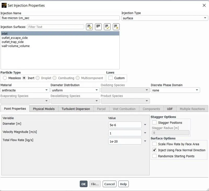
The flow velocity at the inlet of the cyclone separator is set to 5 m/s. It is assumed that the particle velocity is the same as the flow velocity at the inlet. This assumption allows for a simplification of the simulation, as the effect of the particle's inertia is not considered, and allows the focus on the performance of the cyclone separator under the defined flow conditions.
CASE1:
Size of the particle 5micrometers
Inlet Velocity of fluid=5m/sec
Particle Velocity=Flow velocity
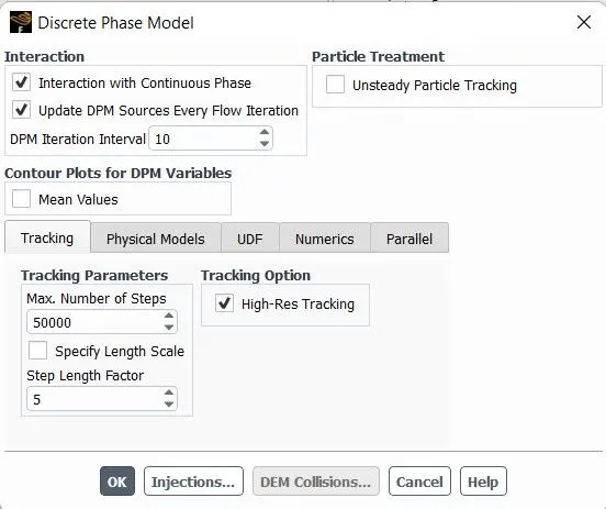
The simulation is set up to enable the "Interaction with Continuous Phase" option which allows for coupled flow modeling. This allows for the interactions between the fluid and the particles to be treated as mutual interactions. Additionally, "Update DPM Sources Every Flow Iteration" is enabled in order to calculate the particle source terms at every iteration. This option is recommended for unsteady simulations, as it allows for more accurate modeling of the particle behavior over time.
The DPM iteration interval is set to 10, which controls the frequency at which the particles are attracted. Additionally, the tracking parameters are set to 50000 for the steady case, and the step length factor is set to 5. This allows for the control of the size of the time step and fine-tuning the time step according to the simulation. The "Specify Length Scale" option is not used in this simulation, which is also used to control the time step size by dividing the length scale with the velocity of the discrete particle and velocity with the velocity of the continuous phase.
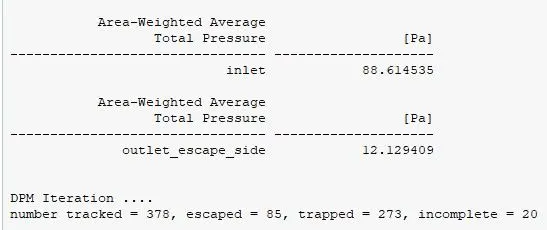
As the “escape” DPM condition is given to the outlet-top in this case, so outlet-top is considered in pressure drop calculation.
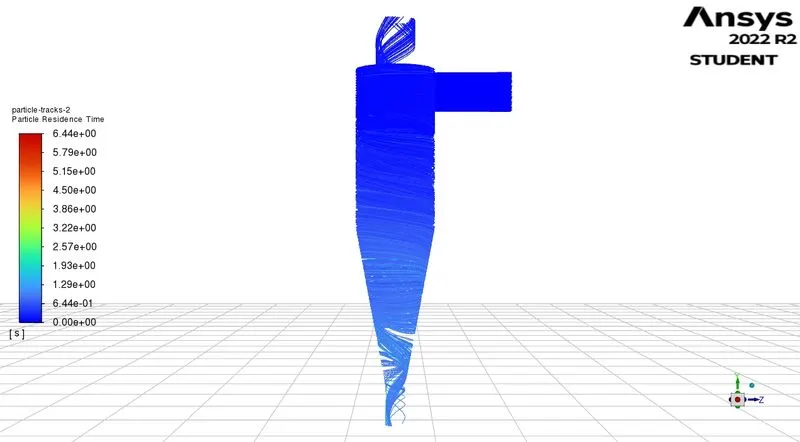
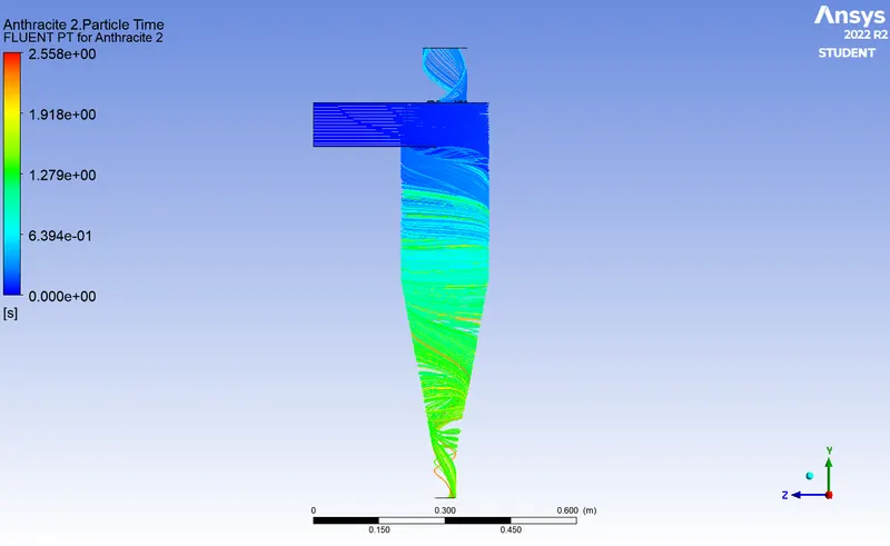
The plot typically shows the residence time of particles on the y-axis and the position along the flow direction on the x-axis. The plot can be generated by tracking the movement of particles in a flow field, either through experimental measurements or numerical simulations.
The residence time plot can provide information on several aspects of the flow:
- The overall mixing efficiency of the flow, which is indicated by the distribution of residence times.
- The flow's characteristic time scales, which can be inferred from the widths of the peaks in the residence time plot.
- The presence of recirculation zones or stagnant regions in the flow, which can be identified by long residence times in specific regions of the plot.
- The flow's ability to transport particles downstream, which is indicated by the overall shape of the plot.
In this particle residence time plot is a useful tool for understanding the transport and mixing of particles in a fluid flow. It can provide insights into the flow's mixing efficiency, characteristic time scales, and the presence of recirculation zones or stagnant regions.
- The particle residence time plot indicates that the flow is properly mixed.
- The plot shows that particles are being transported efficiently downstream.
- There is no evidence of stagnation in the flow.
- There is no accumulation of particles in any specific region of the flow.
- The flow is characterized by a good mixing efficiency.
- There is no indication of recirculation zones or stagnant regions in the flow.
- The flow's characteristic time scales can be inferred from the widths of the peaks in the residence time plot.
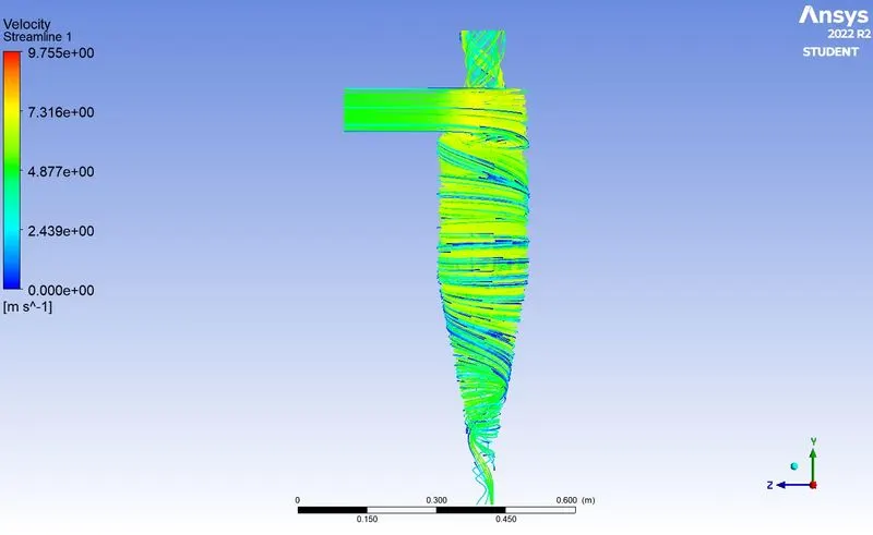
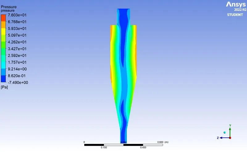
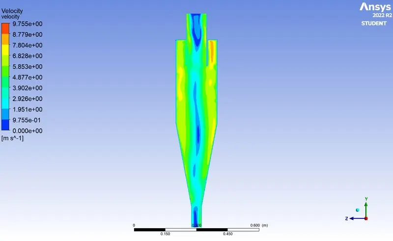
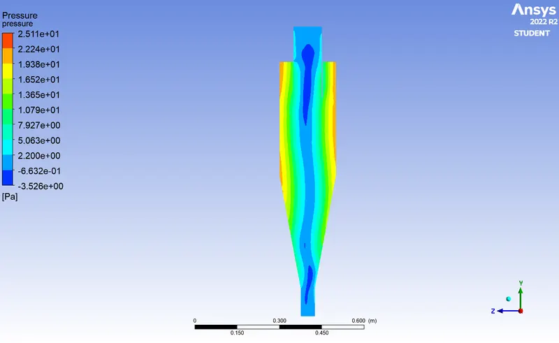
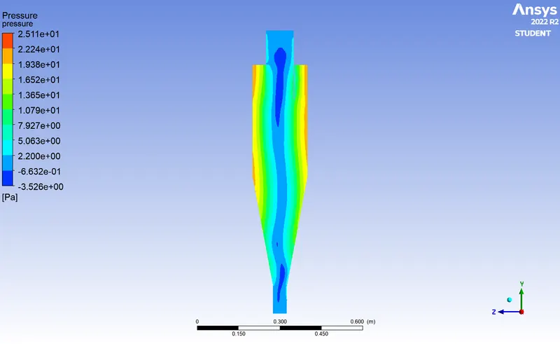
- The pressure plot represents the pressure at various positions near the walls, at the center, bottom trap side, and top escape side.
- The flow motion is characterized by swirling, which leads to the development of a low-pressure zone at the center of the cone.
- The flow's swirling motion and the particles are affected by centrifugal forces.
- The centrifugal forces play a role in the flow and particle dynamics, causing a low pressure zone to develop at the center of the cone.
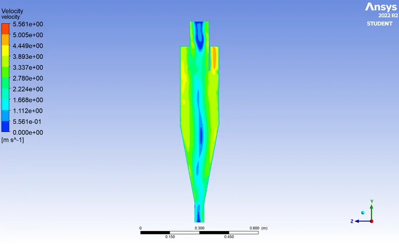
- The flow enters the cyclone in a tangential direction, leading to high flow velocity at the entry point.
- As the flow velocity of the fluid and the dispersed particle velocity are the same, there are no inertial forces acting on the particles.
- The dispersed particles in the flow are carried towards the walls of the cone and downstream, resulting in the trapping of particles at the bottom of the cone.
- Due to the low-pressure zone and swirling flow near the center of the cone, some particles are carried upwards, resulting in the escapement of particles.
- The centrifugal forces caused by the swirling flow, results in particles being trapped at the wall and bottom of the cone while some particles are able to escape via the top of the cone.
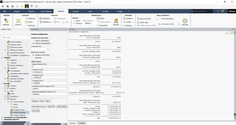
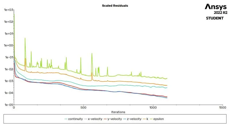
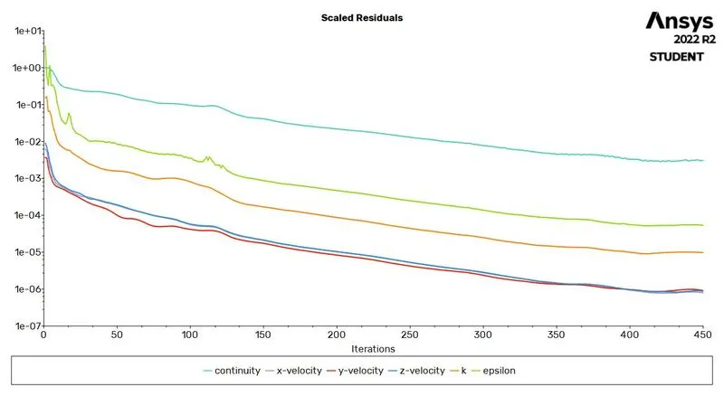
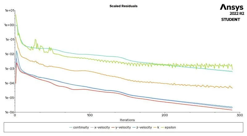
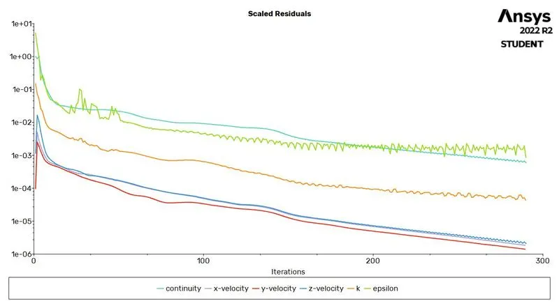
- The scaled residuals indicate that the kinetic energy of flow turbulence and the rate of dissipation of turbulence are fluctuating in the form of spikes.
- These spikes suggest that there may be a problem with the convergence of the simulation.
- The simple method used in the simulation is less efficient when compared to a coupled method, as it is not able to converge the solution as expected.
- The spikes in the residuals may be caused by a variety of factors including numerical instability, inappropriate solver settings, ill-conditioned problem and a poor definition of the problem.
- The simple method may not be able to capture the interactions between different physical phenomena and thus less efficient in giving the accurate results.
POST PROCESSING:
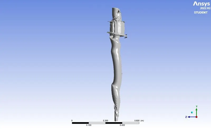
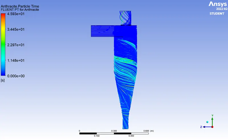
PARTICLE RESIDENCE TIME AND CORE VORTEX REGION:
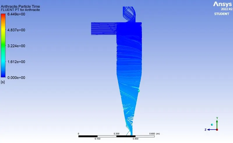
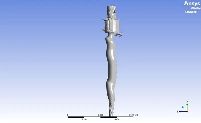
- The particle residence time plot shows that one particle remained inside the cyclone even after additional iterations.
- This suggests that the particle is not being transported efficiently downstream and is getting stuck inside the cyclone.
- The particle may be trapped in a recirculation zone, or it may be experiencing a high level of drag force and unable to move with the flow.
PRESSURE AND VELOCITY CONTOUR:
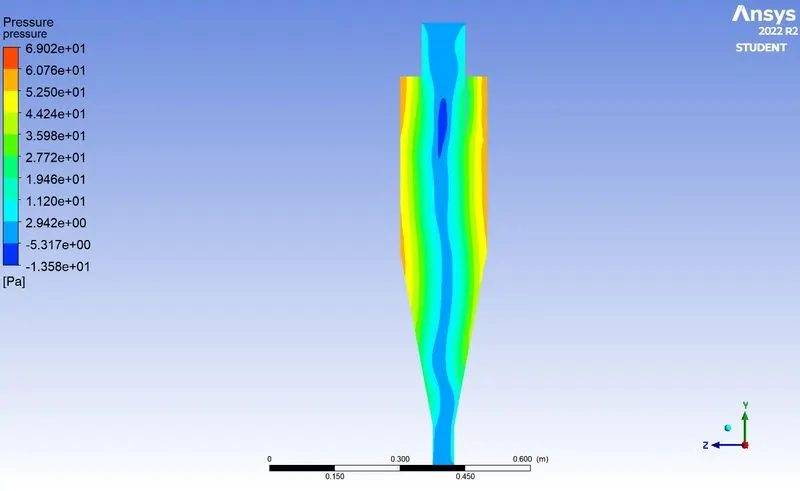
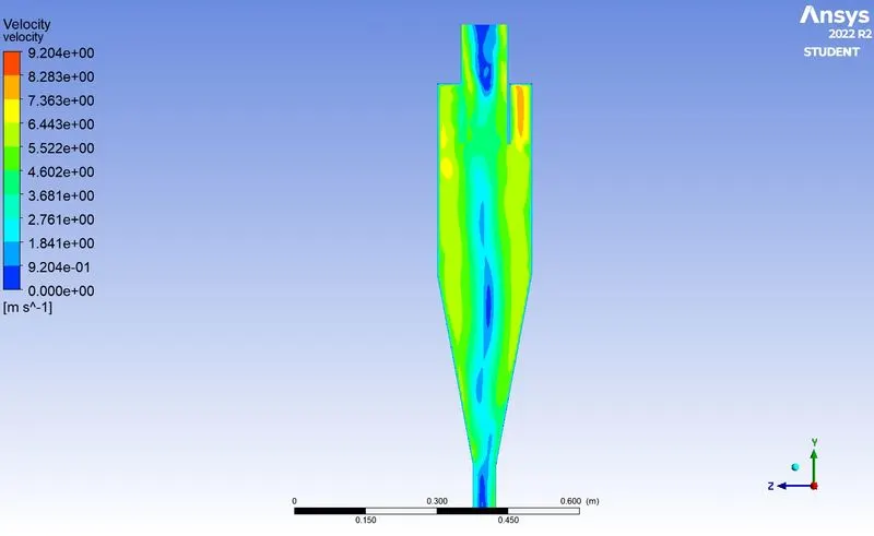
- The SIMPLE method involves predicting the initial pressure and then correcting it based on the pressure values in neighboring cells.
- The pressure contour shows that the pressure at the center of the cone is slightly higher when compared to the coupled method.
- The velocity at the center is also higher in the SIMPLE method.
- This suggests that the swirling motion of the flow is less pronounced in this simulation process as compared to the coupled method.
- The high pressure and velocity in the center may be caused by the lack of swirl motion which is not well captured by the SIMPLE method.
- This is an indication that the SIMPLE method may not be able to capture the flow dynamics as accurately as the coupled method, which is able to capture the swirling motion well.
By changing the flow velocity and particle velocity diameter flow simulations were done. Below are the results obtained.
| PARTICLE SIZE in micrometers |
FLOW VELOCITY in m/sec |
TOTAL PRESSURE in pascals |
OUTLET PRESSURE (ESCAPE) |
PRESSURE DROP | TRACKED PARTICLES | TRAPPED PARTICLES | SEPARATOR EFFICIENCY |
| 1 | 3 | 29.9 | 3.97 | 14.07 | 378 | 309 | 81.75 |
| 3 | 3 | 29.91 | 3.97 | 14.06 | 378 | 313 | 82.80 |
| 5 | 3 | 30.1 | 4 | 26.1 | 378 | 270 | 71.42 |
| 5 | 1 | 30.09 | 3.99 | 26.1 | 378 | 270 | 71.42 |
CASE 3: Flow velocity & Particle Velocity 1m/sec of Particle diameter 3micrometer.
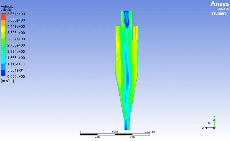
- The results of the simulation indicate that the coupled method provides more efficient and accurate results compared to the simple method.
- The efficiency of the simulation does not change significantly with changes in velocity.
- The simulation is most efficient for a particle size of 3 micrometers and a flow velocity of 3 m/s for this specific geometry of the cyclone.
- The coupled method is able to capture the flow dynamics more accurately, resulting in better mixing and particle transport.
- The SIMPLE method is less efficient and less accurate in capturing the flow dynamics and particle transport.
- Overall, the coupled method is recommended for this specific geometry of the cyclone and for particle size of 3 micrometers and flow velocity of 3 m/s for efficient and accurate results.