Project - Analysis of a practical automotive wiring circuit
Identify each of the major elements in the above automotive wiring diagram.Explain the purpose and working of any three elements briefly.
An electric circuit diagram in an automotive system is necessary for several reasons. It helps in understanding how the system works, troubleshooting issues, modifying and customizing the system, and maintaining the components. By providing a clear picture of the electric system, it makes it easier to identify faulty parts and replace them. In summary, a circuit diagram is an essential tool for maintaining and repairing an automotive electrical system.
Battery:
A battery is a device that stores electrical energy in the form of chemical energy and releases it as electrical energy when required. Batteries are commonly used in a wide range of electronic devices, from small portable devices such as cell phones and laptops to larger devices such as electric vehicles and backup power systems.
Ignition Switch:
In an automotive electrical drawing, an ignition switch is typically represented as a switch symbol. The ignition switch is a key-operated switch that controls the flow of electrical power to the vehicle's ignition system, fuel system, and other components.
The ignition switch is typically located on the steering column or dashboard of the vehicle, and is connected to the battery and other electrical components through a series of wires and fuses. When the key is turned in the ignition switch, it completes a circuit that allows electrical power to flow to the starter motor, fuel pump, and other systems.
The ignition switch may also be connected to other components related to the vehicle's security system, such as an immobilizer or alarm system. Proper wiring and connection of the ignition switch is important to ensure reliable and safe operation of the vehicle.
In some modern vehicles, the traditional key-operated ignition switch has been replaced with a push-button or electronic ignition system, which may be represented differently in electrical drawings.
Fuel Gauge:
In an automotive electrical drawing, a fuel gauge sensor is typically represented as a resistor. The fuel level sensor is a variable resistor that changes its resistance based on the level of fuel in the tank.
The fuel gauge sensor is typically located in the fuel tank, and is connected to the fuel gauge on the dashboard or instrument cluster of the vehicle. As the level of fuel in the tank changes, the resistance of the fuel gauge sensor changes as well. This change in resistance is detected by the fuel gauge, which then displays the fuel level to the driver.
The fuel gauge sensor is usually connected in series with the vehicle's electrical system, and may be connected to other sensors or components related to the fuel system, such as a fuel pump or fuel level warning light. Proper wiring and connection of the fuel gauge sensor is important to ensure accurate readings and safe operation of the vehicle.
Ammeter:
An ammeter in an electric vehicle (EV) functions similarly to an ammeter in a conventional gasoline-powered vehicle. It measures the amount of electrical current flowing through the circuit in the EV.
In an EV, the ammeter is typically located on the dashboard or instrument cluster, and is used to monitor the charging and discharging of the vehicle's battery. When the EV is charging, the ammeter indicates the amount of current being drawn from the charging station or charging system. When the EV is in use, the ammeter indicates the amount of current being drawn from the battery to power the motor and other electrical systems.
It is important to use an ammeter that is properly rated for the circuit being tested, to avoid damage to the meter or inaccurate readings. In addition, because EVs use high-voltage batteries and electrical systems, it is important to follow proper safety procedures when working with ammeters or other electrical components in an EV.
Generator:
In an automotive electrical drawing, a generator is typically represented as a symbol that looks like a circle with a letter "G" inside. The generator is an electromechanical device that converts mechanical energy from the engine into electrical energy that can be used to power the vehicle's electrical systems and recharge the battery.
The generator is usually driven by a belt connected to the engine's crankshaft, and is controlled by the vehicle's regulator and battery management system. As the engine rotates the generator, it generates an alternating current (AC) that is converted into direct current (DC) by the regulator and sent to the battery and other electrical systems.
The generator may also be connected to other sensors and components related to the vehicle's charging system, such as an alternator warning light or voltage regulator. Proper wiring and connection of the generator and related components is important to ensure reliable and safe operation of the vehicle.
Current and Voltage Regulator:
Current and voltage regulators are electronic circuits that are commonly used in power supply applications to maintain a stable output voltage or current.
A voltage regulator is a device that maintains a constant output voltage, regardless of changes in input voltage or load current. It is designed to protect the load from overvoltage, undervoltage, and voltage fluctuations. There are two types of voltage regulators: linear and switching.
A linear voltage regulator uses a series pass transistor to regulate the output voltage. It works by adjusting the voltage drop across the series pass transistor to maintain a constant output voltage. Linear regulators are simple, low cost, and easy to use, but are not very efficient.
A switching voltage regulator uses a high-frequency switching circuit to regulate the output voltage. It works by varying the duty cycle of the switching circuit to maintain a constant output voltage. Switching regulators are more complex and expensive than linear regulators, but are more efficient and can handle higher input voltages.
A current regulator is a device that maintains a constant output current, regardless of changes in input voltage or load resistance. It is used to protect the load from overcurrent and to maintain a constant power output. There are two types of current regulators: series and shunt.
A series current regulator uses a series pass transistor to regulate the output current. It works by adjusting the voltage drop across the series pass transistor to maintain a constant output current. Series regulators are simple, low cost, and easy to use, but are not very efficient.
A shunt current regulator uses a shunt transistor to regulate the output current. It works by adjusting the shunt current to maintain a constant output current. Shunt regulators are more complex and expensive than series regulators, but are more efficient and can handle higher output currents.
Both current and voltage regulators are commonly used in automotive applications, such as in the alternator charging system and electronic control modules.
Starter:
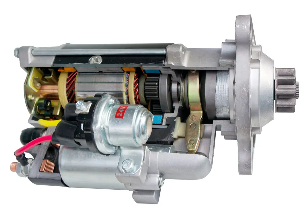
A starter is an electric motor used to start a gasoline or diesel engine. It is typically located near the bottom of the engine and is attached to the flywheel or flexplate via a starter drive mechanism.
When the driver turns the ignition key or presses the start button, an electrical signal is sent to the starter solenoid, which engages the starter motor with the engine's flywheel or flexplate. The starter motor then turns the engine over, allowing it to begin running on its own.
Once the engine starts running, the starter disengages from the flywheel or flexplate and the engine continues to run on its own. The starter motor itself is typically powered by the vehicle's battery, and may draw a significant amount of electrical current during operation.
The starter is a critical component of the engine starting system, and any problems with the starter motor or associated components can prevent the engine from starting or cause it to start slowly or inconsistently.
Ignition Coil:
In an automotive electrical drawing, an ignition coil is typically represented as a transformer symbol with two coils and a core. The ignition coil is a component of the ignition system that converts the battery voltage into a higher voltage that is required to ignite the fuel mixture in the engine's cylinders.
The ignition coil is usually connected to the vehicle's distributor and spark plugs through a series of wires. When the distributor rotor spins, it sends a signal to the ignition coil to generate a high-voltage spark that jumps across the gap between the spark plugs, igniting the fuel mixture in the engine.
The ignition coil may also be connected to other components related to the vehicle's ignition system, such as the ignition switch, distributor cap, and ignition control module. Proper wiring and connection of the ignition coil and related components is important to ensure reliable and safe operation of the vehicle.
Distributor:
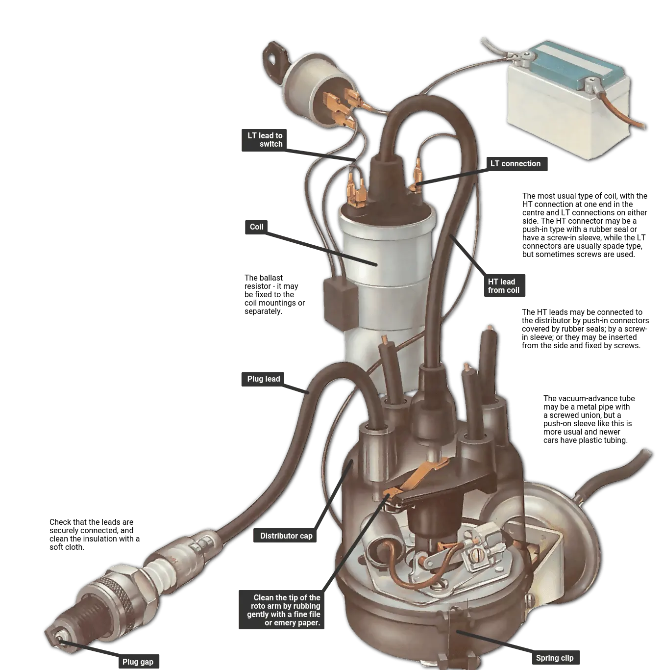
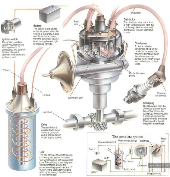
In an automotive electric drawing, a distributor refers to a component used in the ignition system of internal combustion engines. Its primary function is to distribute high voltage electricity from the ignition coil to each spark plug in the engine in the correct firing order. This is done by routing the electrical signal through a rotating arm called the rotor, which passes by a series of electrical contacts called the cap and rotor.
The distributor is typically driven by the engine's camshaft, and rotates at half the speed of the engine. As the rotor rotates, it passes by the contacts in the distributor cap, sending high voltage electricity to the spark plug that is currently firing in the engine's firing order. This process repeats for each spark plug in the engine, ensuring that the fuel mixture in each cylinder is ignited at the correct time.
Modern engines often use electronic ignition systems, which replace the mechanical distributor with an electronic control module and individual coil packs or ignition coils for each spark plug. However, older vehicles and some performance engines still use distributors as part of their ignition system.
Breaker:
In an automotive electric drawing, a breaker usually refers to a circuit breaker or fuse. These are safety devices designed to protect the electrical system from overloads or short circuits that can cause damage or even start a fire.
A circuit breaker is an automatically operated electrical switch that protects an electrical circuit from damage caused by excess current from an overload or short circuit. It is designed to interrupt the flow of current in the event of an overload or short circuit. Once the fault has been corrected, the circuit breaker can be reset manually.
A fuse, on the other hand, is a safety device that protects the electrical system by melting and breaking the circuit when there is an overload or short circuit. Fuses come in different ratings and are designed to melt and open the circuit at a predetermined current level.
Both circuit breakers and fuses are typically located in the vehicle's fuse box or power distribution center, and are labeled with their amperage ratings and the circuits they protect. In the event of an electrical problem, a blown fuse or tripped circuit breaker can often be the culprit, and must be replaced or reset before the electrical system can function properly again.
Foot Selector Switch:
A foot selector switch in an automotive electric drawing is a switch that is operated by the driver's foot and is used to select different gears in a manual transmission vehicle. The switch is typically located on the floor of the vehicle, near the driver's seat. When the driver presses the switch, it sends an electrical signal to the transmission control module (TCM) to engage the selected gear. The foot selector switch is an important component of the transmission system and allows the driver to control the vehicle's speed and acceleration.
Lighting System :
Sealed Beam
Dome Light
Dome Light Switch
Tail Stop
Parking Lamp
Light Switch, Fuse
Beam Light
Horn Button.
Switches:
STDP LT switch- Single Throw Double Pole Latch Toggle Switch
Foot Selector Switch
Fuse:
Fuses are electrical safety devices designed to protect electrical systems and devices from damage caused by excessive current flow. The working principle of a fuse involves a metal wire or filament that melts when the current passing through it exceeds a certain level, thereby breaking the electrical circuit and preventing further current flow.
A fuse typically consists of a fuse element, which is a thin wire or filament made of a material with a low melting point, such as copper or silver. The fuse element is enclosed in a glass or ceramic tube that is filled with a non-conductive material, such as sand or quartz. The tube has metal caps or ends that are connected to the electrical circuit.
When the current flowing through the circuit is within the normal operating range, the fuse element remains intact and the circuit is uninterrupted. However, when a fault occurs, such as a short circuit or overload, the current flow increases rapidly, causing the fuse element to heat up and melt. As a result, the circuit is broken, and the flow of current is interrupted, preventing damage to the electrical system and devices.
Fuses are designed with a specific current rating, which indicates the maximum amount of current the fuse can safely handle without melting. It's essential to choose a fuse with the appropriate current rating for the specific application to ensure effective protection. If the current rating of the fuse is too low, it may blow frequently, causing inconvenience and potentially damaging the electrical system. Conversely, if the current rating is too high, it may not provide adequate protection and may even lead to dangerous situations.
Overall, fuses are simple and effective devices that play a crucial role in protecting electrical systems and devices from damage due to excessive current flow.
3.If the total load is 10A from battery, what should be the fuse rating?
Power= Voltage* Circuit Current.
Here it is known that the power through the circuit which is also called as load is of 10Ampere. So , it will be good to choose the fuse atleast 30-50% greater than the load. So fuse maybe choosen of from 13-15Amperes.
4.If 500W is the load, what is the voltage and capacity of battery you recommend?
Given details,
Load=500Watts
We need to find the Capacity of the battery rewuired for this particular consumption.
From Ohm's law, we know
Power= Voltage* Current.
Lets assume battery is of 12V usually uses in automobile.
Energy of a battery is
E=Power*Time
E=500*1 hour
E=500Wh.
Capacity of a battery,
Energy= Q(Capacity)*Voltage of battery
Q=E/V
Q=500Wh/12V
Q=41.67Ah.
So, from the above calculations we know that we need a battery of capacity greater than 41.6Ah to compensate losses in the system. Standard models are available from 45Ah. We can choose 45Ah or 50Ah,55Ah based on further calculations.
5.Identify any two elements which are connected parallel to each other. Why they are connected in parallel?
Sealed Beam lights and Horn are connected in parallel, because these components required same voltage but different current.
Sealed beam requires less current and Horn requires High current based on their resistance.
6.Identify any two elements which are connected in series. Why they are connected in series?
Battery and Ammeter:
An ammeter should be connected in series with the circuit whose current is to be measured.
Connecting an ammeter in parallel with the circuit can result in a short circuit, as the ammeter will offer a negligible resistance path for the current to flow through. This can cause a dangerously high current to flow through the ammeter, potentially damaging the meter and the circuit.
When an ammeter is connected in series with the circuit, it becomes a part of the circuit, and the current flows through the ammeter, providing an accurate measurement of the current. The ammeter should be connected in such a way that the current flows from the positive terminal of the source, through the ammeter, and then through the load and back to the negative terminal of the source.
Battery and Starter:
The starter motor in an automotive electrical system needs to be connected in series with the battery and the rest of the electrical system, rather than in parallel, because the starter motor requires a very high current to operate.
When the starter motor is engaged, it draws a very large current from the battery, typically in the range of 100 to 200 amps, for a short period of time, usually a few seconds. If the starter motor were connected in parallel with the rest of the electrical system, it would create a short circuit, as the large current draw would bypass the rest of the electrical system.
By connecting the starter motor in series with the rest of the electrical system, the high current draw is limited to the starter motor and does not affect the rest of the system. This allows the battery to supply the necessary current to the starter motor without overloading the rest of the system, which would cause damage to the wiring, fuses, and other electrical components.
So, connecting the starter motor in series with the battery and the rest of the electrical system is necessary to ensure that the starter motor can operate safely and efficiently without damaging other components in the system.