Door Arm Rest Week 8 Challenge
AIM:
To make a model from the provided class-A surface.
INTRODUCTION:
CLASS-A SURFACE: A surface made by the designer which is given as an input to the plastic modeller to work on. It is an aesthetic surface and the outermost surface.
CLASS-B SURFACE: A surface after a certain thickness from the class-A surface is a class-B surface. This is the surface that contains engineering aspects of a model.
CLASS-C SURFACE: A surface that joins class-A and class-B surfaces is a class-C surface.
METHODOLOGY: In this model, we have focused on the following things:
1. Tooling axis
2. Draft analysis
3. Class-B surface
4. Class-C surface
5. Making a solid model from the surface.
CLASS-A surface:
Surface gave by the Styling team to Design Engineer.
1. Check the given class A surface for any surface openings neglecting the feature opening using the boundary feature. Fix the openings using the Join feature if needed.
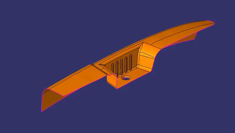
2. Create a tooling axis exactly at the centre of the pocket feature, by extracting the base surface of the pocket, creating a centre point on the extracted surface and create a line from the point facing the Z direction at 90 degrees from the base as shown below.
Tooling for X-axis

Tooling for Y-axis
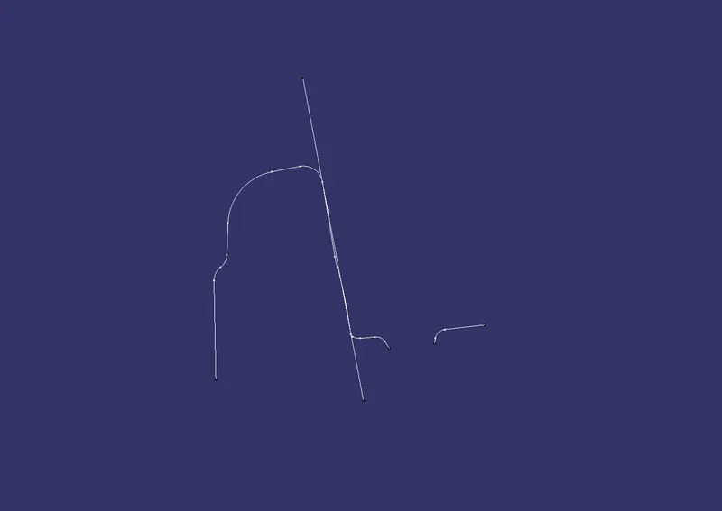
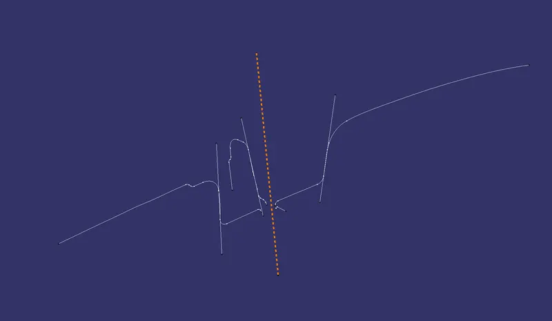
Tooling for X-Y axis using Bi-section Method
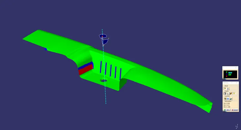
DRAFT ANALYSIS ON CLASS-A surface
The styling team has not given any draft to sidewalls, the flange that's why it's not Green because the Red is considered a Negative Draft.
Slider Tooling Direction
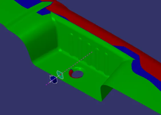
As you can see the cutout is not clearing with the main tooling direction. So, we have to make another tooling direction for that indivisiual cutout. So, to that we have to make an Intersection for our core tooling. we extract the wall and Project the point on surface at the center. and its our Origin for axis system. Make a sketch on z-y plane and create an Intersection. and draw a line at 3 deg. from the bottom.
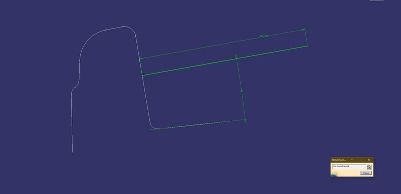
Draft Analysis for Cutout
CLASS-B surface
A surface after a certain thickness from the class-A surface is a class-B surface. This is the surface that contains engineering aspects of a model.
Extract the flat like surface and trim them. (Lets calls this Flange 1)
CLASS-B surface
A surface after a certain thickness from the class-A surface is a class-B surface. This is the surface that contains engineering aspects of a model.
Extract the flat like surface and trim them. (Lets calls this Flange 1)
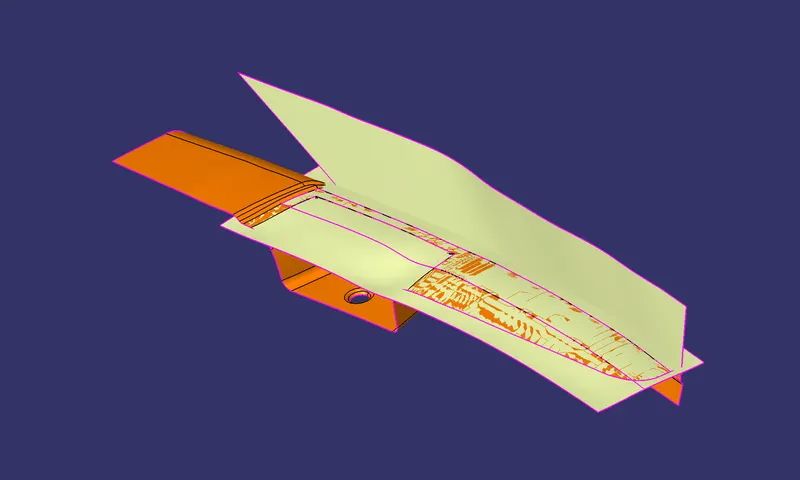
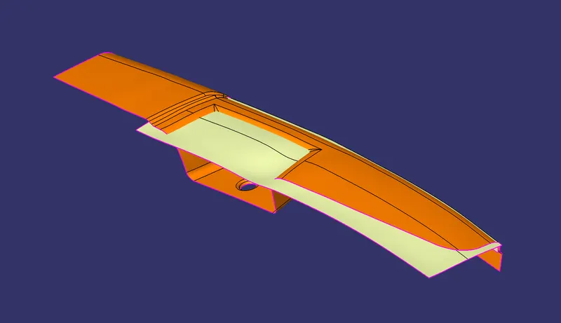
Flange 2
Extract->Extend->trim
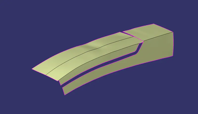
Cutout
Extract->Extend->trim
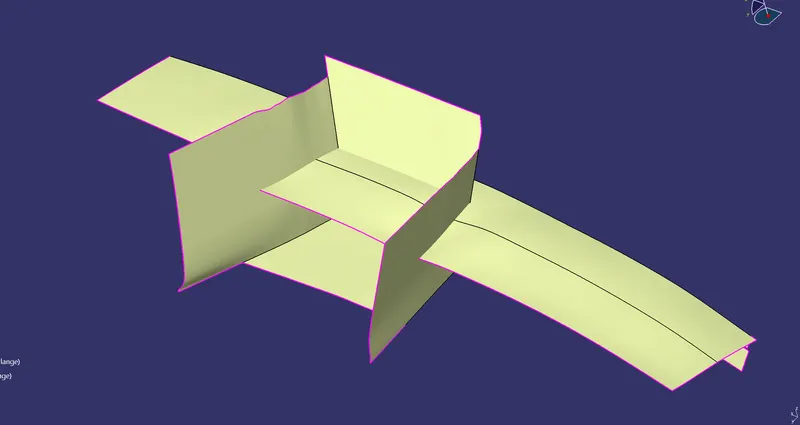
Joining the Flange 1 & 2
1. Create a point on Class A-Surface as shown in below picture and insert an axis system on that point.
Sweep->split->Offset->Trim
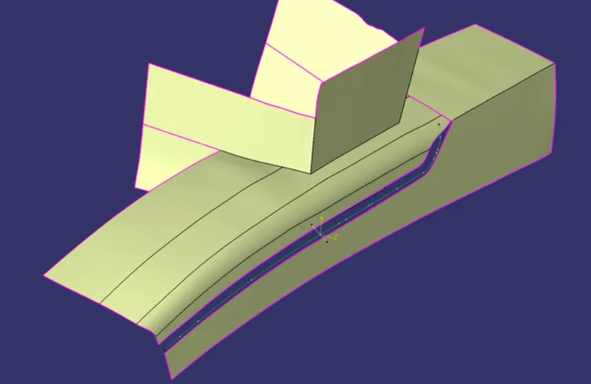
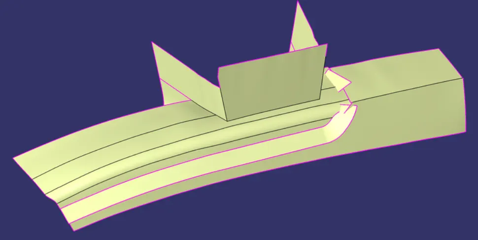
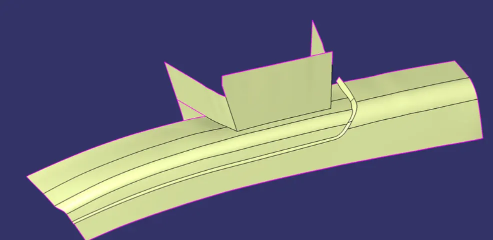
Class-B surface
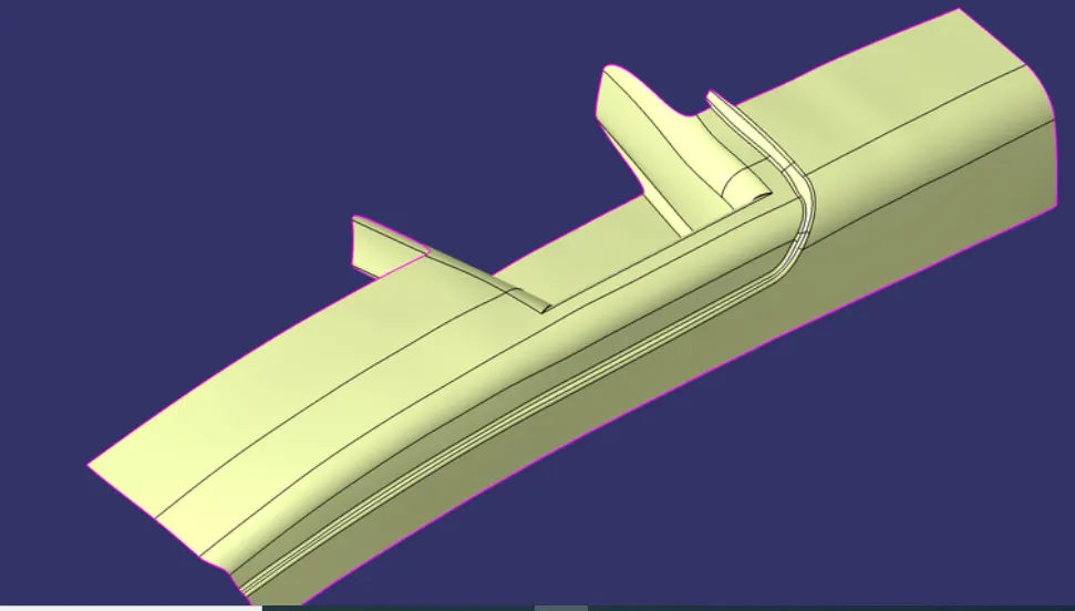
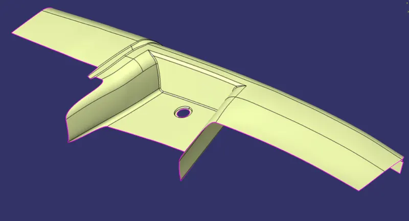
Class-c Surface
Extract the flat and simple curves from the Class A-Surface, and turn them to smooth curve and sweep along the tooling axis by selecting "With draft direction" as subtype in "Swept surface definition" dialog box. Tooling axes are selected as per requirement.
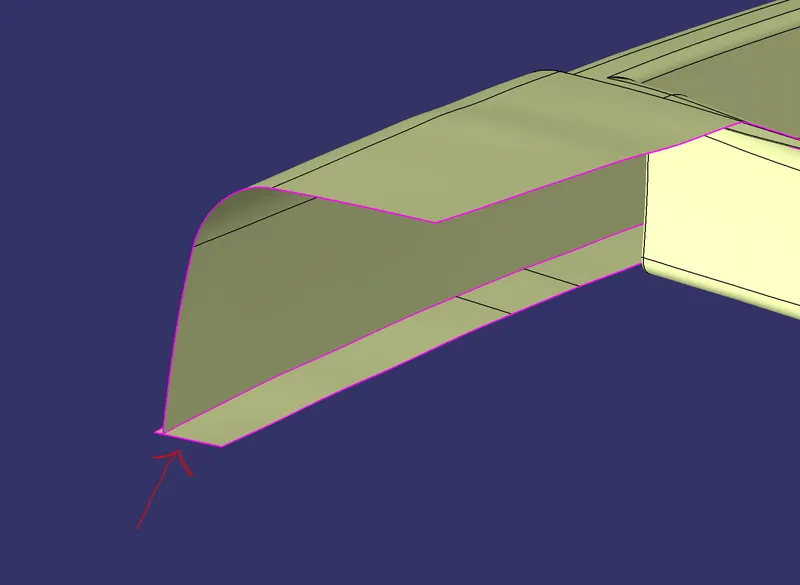
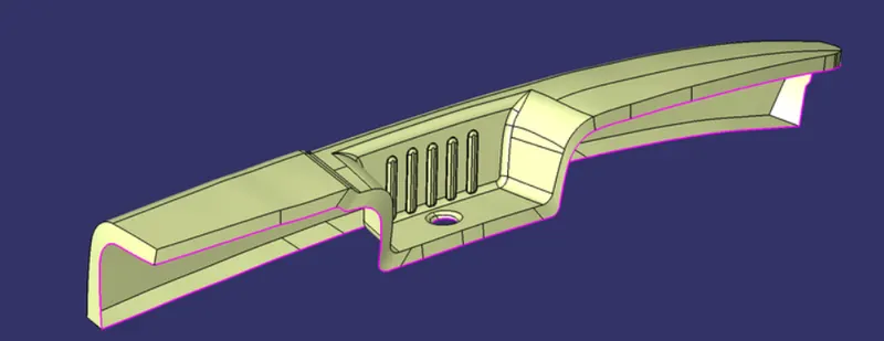
Joining Class-C & B
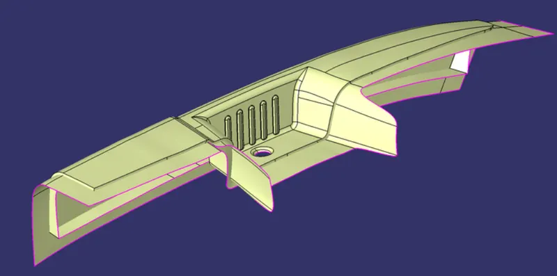
Close Surface Body
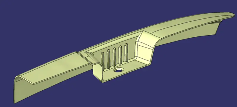
Converting Surface to Solid
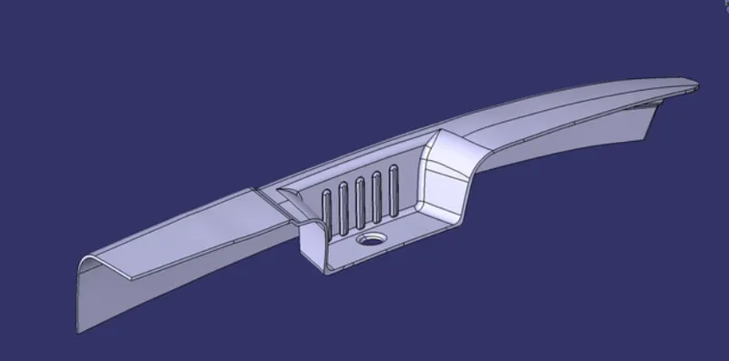
Draft Analysis on Solid Body
Now again i will do the draft analysis but this time for the whole solid body. so again here i will do two draft analysis first one for the main tooling axis and the second for the side core tooling axis. The first draft analysis using the main tooling direction is shown below:
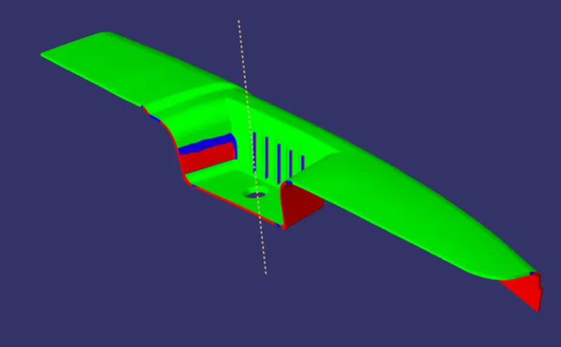
As you can see the whole part is clearing with the main tooling direction. there are some RED, BLUE color coding which means this part is not producible with this design. so in the image below, i am going to show you where and why it's not clearing with this tooling.
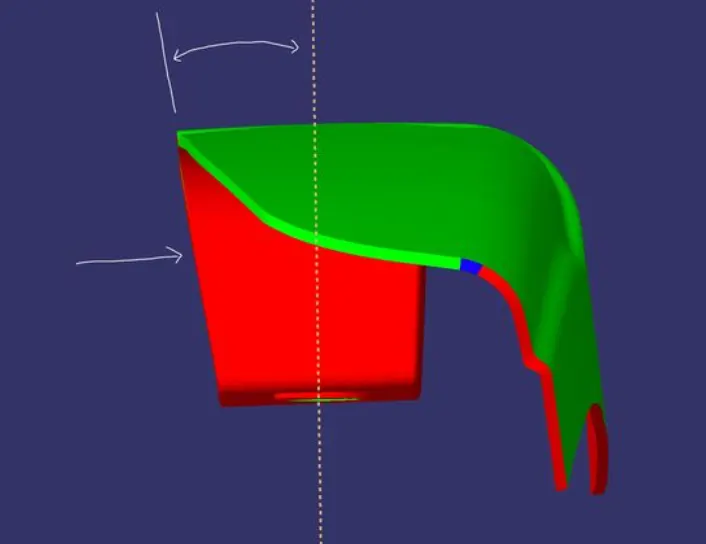
So, as you can see the red portion is a Negative draft. that means it's going inside and it has a greater angle from the tooling dir. that why its not clearing.
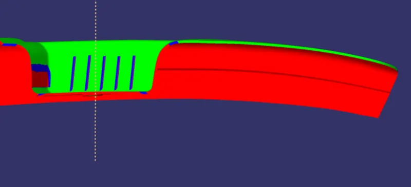
So, on the right side the flange is going inside and not going to clear.
So, to clear the cutout region we have to create another tooling. and the walls that were not clearing with the main tooling. this tooling is called Slider Tooling direction. our main purpose is that to design a part that will be clear with the main tooling and we don't wanna use any other tooling because that will complicate things and it's gonna be expensive.
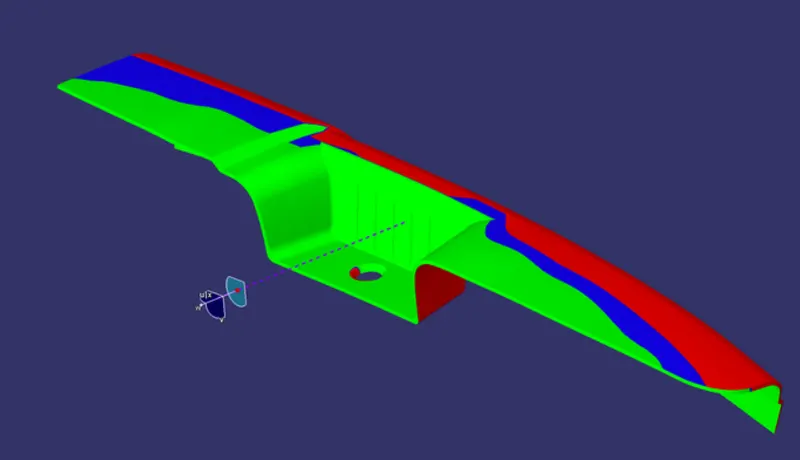
Conclusion:-
What we found with this Draft analysis is that the Class-A surface is not good it's not manufacturable. and Class-A is given by the styling team they have to make changes Design Engineer is not authorized for it.