Photo Realistic Rendering
Assembly and rendering of an American chopper
Objective: To assemble an American chopper and render it with proper views and environments.
Introduction: For studying different tools and features of the SOLIDWORKS, this project was selected. During the design of each parts efforts were made to use each and every tool in SOLIDWORKS and to get familiarized in it. This project also aims in familiarization of SOLIDWORK VISUALIZE for rendering and editing.
Design Methodology:
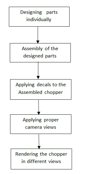
As shown in the flow chart at first, I started by designing individual parts of the chopper in SOLID WORKS. After designing the part models, I switched to assembly model and assembled every part with sufficient relations. Once assembly was complete, I applyed proper decals and camera views for rendering. Then with different views and environments the chopper was rendered.
Description:
For the assembly of American chopper at first all the parts should be designed the parts are:
- Transmission Belt
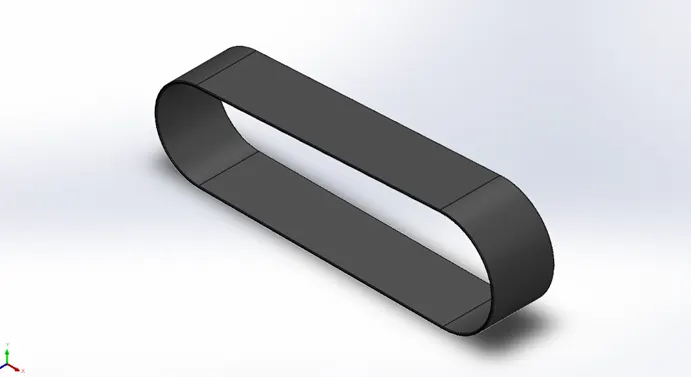
Features used in this design are:
- Line Tool: Used to draw straight lines.
- 3-point arc: To draw arc’s connecting lines.
- Offset entities: It was used to offset the sketch to a specified distance.
- Extruded Boss/Base: This tool helps to extrude a 3-D shape from a 2-D sketch following the parameters that we give. In this case a bind extrude is used from sketch. 2.Kick Stand
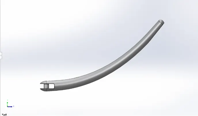
Features used in this design are:
- Loft: Used to create the geometry between both the ellipse
- Ellipse: Used to sketch 2-D sketch of ellipse.
- Dome: To make the end face to a dome like feature, here an elliptical dome is used.
- Split: Was used to remove material from the stand where it touches ground.
- Spline: Used to create curve for loft, these are defined by spline points and spline handles.
- Cut Extrude: To make spacing for connecting to chassis. 3.Front Fender
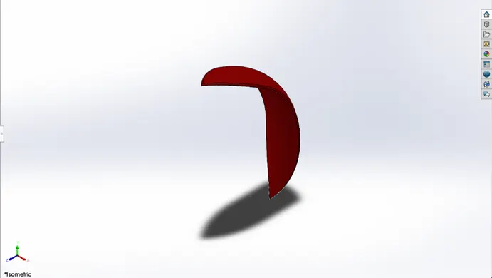
Features used in this design are:
- Revolved Boss/Base: Sketch is revolved based on the centre axis.
- Fillet: To create rounded external surfaces.
- Split: To remove excess shape. 4.Rear Fender
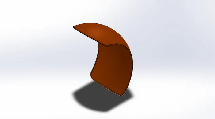
Features used in this design are:
- Revolved Boss/Base: Sketch is revolved based on the centre axis.
- Fillet: To create rounded external surfaces.
- Split: To remove excess shape.
5.Chain
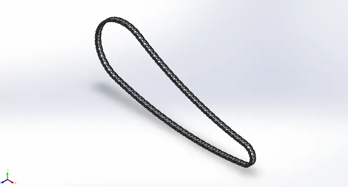
Features used in this design are:
- Curve Pattern: The chain link and pin are patterned around along the path using this option.
- Boss Extrude: To extrude link and pin from 2-D sketch to 3-D shape.
- Mirror: After completing circular pattern in one side its mirrored with midplane 6.Engine
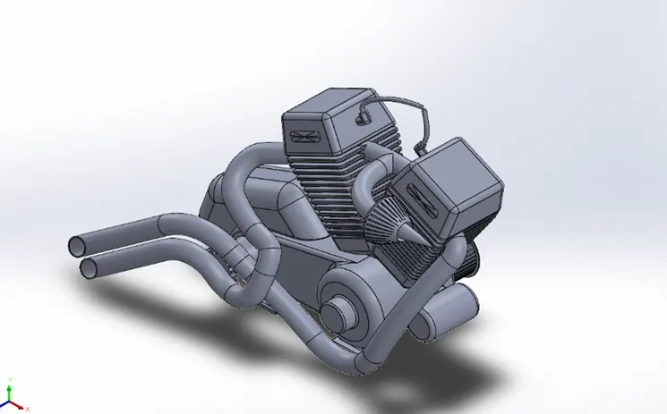
Features used in this design are:
- Projective Curve: This was used to create a path for the sweep of the exhausts from engine. Using this option curves from different planes can be projected to a single curve.
- Linear pattern: Was used to pattern the cut extrude made in one portion of engine.
- Cut Extrude: To Create the pattern on the surface of engine.
- Sweep: Used to make the exhausts.
- Revolve:
- Split: To cut the end of the exhaust. 7.Front wheel:
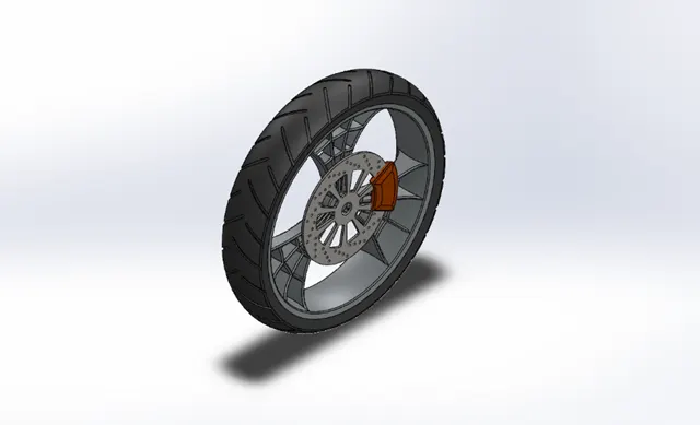
- Revolve: To create rim of the wheel and Rubber part of wheel.
- Boss Extrude: To create the shape of the alloy.
- Cut Extrude: To create the cut shapes in the alloy, rotor and in tier.
- Cut Revolve: To cut excess alloy material.
- Combine: Extrudes were done with merge results off, thus after all extruders required parts are merged by using combine.
- Chamfer: To give shape for the calliper.
- Circular Pattern: To patter the alloy. 8.Rear Tier:
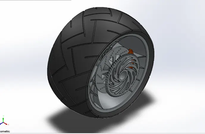
Features used in this design are:
- Revolve: To create rim of the wheel and Rubber part of wheel.
- Boss Extrude: To create the shape of the Rim, sprocket and calliper.
- Cut Extrude: To create the cut shapes in the alloy, sprocket, rotor and in tier.
- Cut Revolve: To cut excess alloy material.
- Combine: Extrudes were done with merge results off, thus after all extruders required parts are merged by using combine.
- Chamfer: To give shape for the calliper.
- Circular Pattern: To patter the alloy. 9.Gas Tank
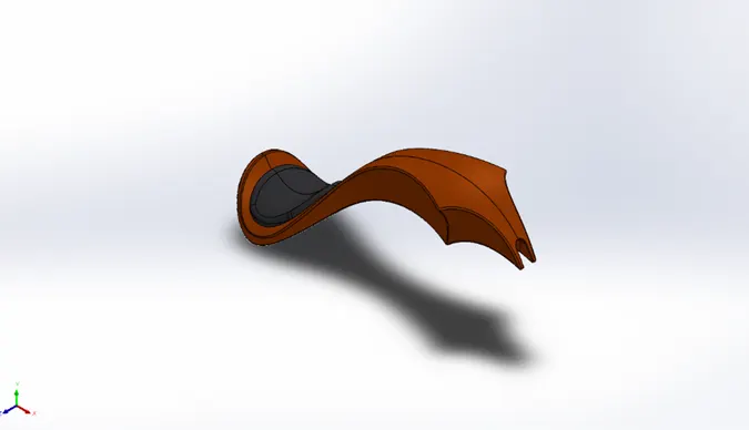
Features used in this design are:
- Surface Sweep: Used to create the top portion the tank.
- Surface Trim: to trim away the excess material from top of the tank.
- Surface Loft: To create side front portion of the tank.
- Boundary Surface: To create rest of the side surface.
- Mirror: The created portion was mirrored on mid plane.
- Surface Knit: Both mirrored portions were knitted together.
- Surface Extrude: Used to extrude the seat to the body of tank.
- Cut-Sweep: To create space for chassis
- Shell: To give hollow space inside.
- Projective Curve: This was used to create a path for the Loft and boundary surface. Using this option curves from different planes can be projected to a single curve. 10.Oil Tank
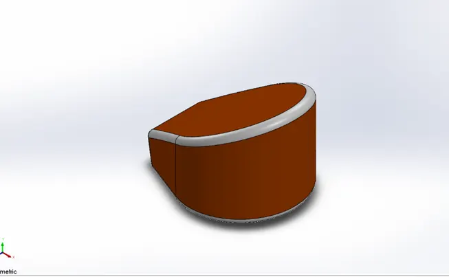
Features used in this design are:
- Boss Extrude: Two shapes were extruded one giving shape of oil tank and one giving elevation of the oil tank.
- Shell: To make the tank hollow inside.
- Combine: To only select the common area of both the extrudes. 11.Front Fork:
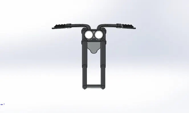
Features used in this design are:
- Revolve: To make one of the Fork and front lamp of the chopper.
- Boss Extrude: To sketch the connection to the fork.
- Linear Pattern: Here two similar things were there thus patterned.
- Revolve Cut: To make a cut in front lamp.
- Sweep: To create the brake wire.
- Projective Curve: to create path for the sweep.
- Mirror: Its mirrored across top plane keeping merge off.
- Combine: Required parts were merged together then. 12.Chassis
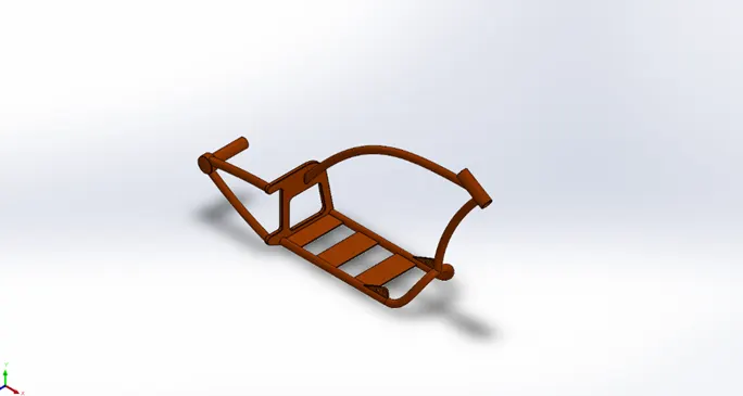
Features used in this design are:
- Projective Curve: To create the tubes present in the chassis making the blue print a reference it was drawn.
- Plane: To create a new plane for references.
- Sweep: Using the created curve path the tubes were drawn.
- Revolve: To create the portion were fork is fitted.
- Split: To remove excess feature.
- Combine: Merge results were off required combine options were used for better results.
The above parts are saved individually and called in assembly model. Each model was called individually starting with chassis and the rest of the parts were attached to the chassis giving proper relationships. Once the assembly of chopper is completed, appropriate decals had been provided and a good camera view was also provided.
Different views of assembled chopper are given below:
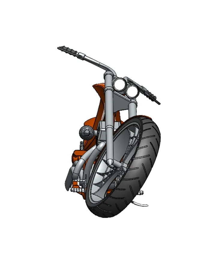
1.Front View
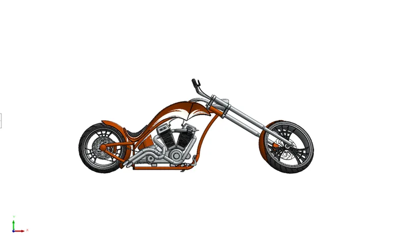
Right side View
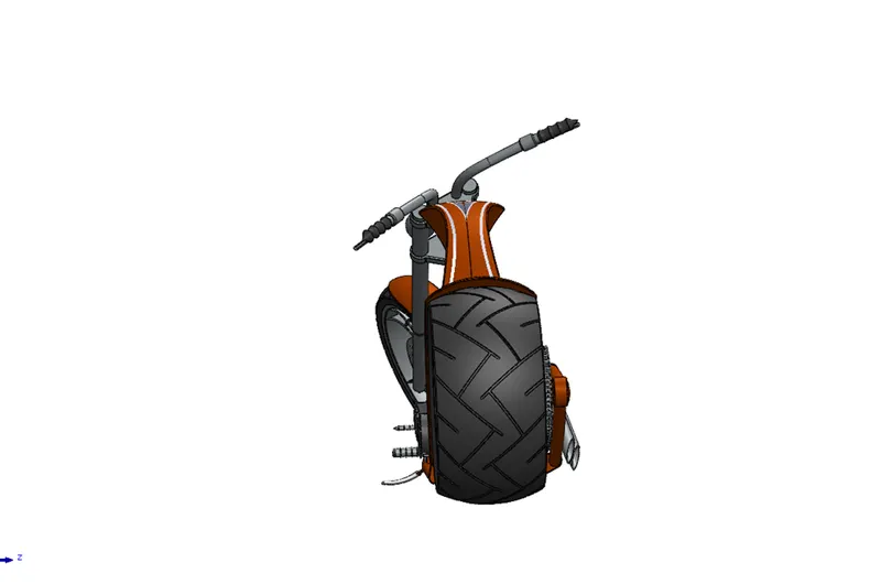
Top View
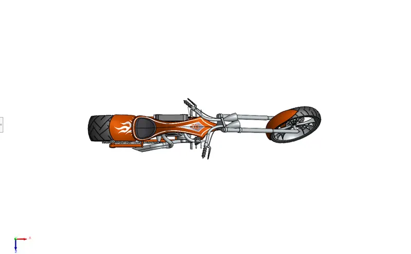
Left Side View
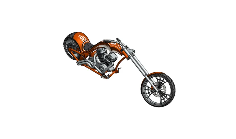
Isometric View
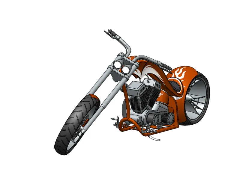
Camera View
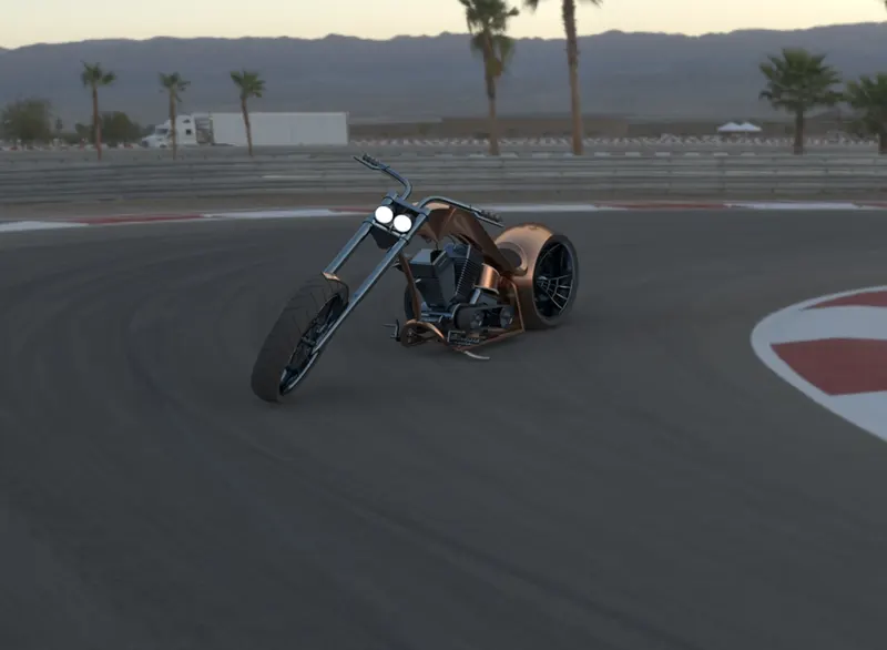
Thus, assembly of chopper was completed, next aim was to render it in SOLID WORK VISUALIZE. Using snap to floor feature the model was imported to visualize and trials with different environments were done. Good renders were selected and rendered in highest quality
Conclusion: The assembly of the Chopper was done.