2D SKETCHING USING CATIA V5 SOFTWARE
AIM: To create a 2D sketch in Catia V5 Software.
PROCEDURE:
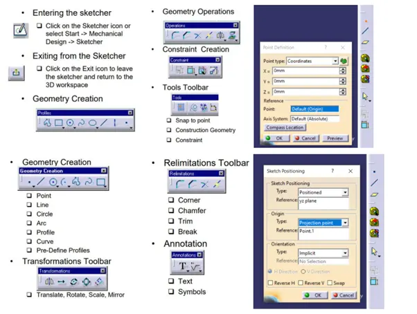
- Open Catia V5 software and go to File-New-Part (Select: Create a geometrical set)
- Create a point at the centre axis with co-ordinates X=0, Y=0 & Z=0.
- Go to Toolbar-Insert-Sketcher -Positioned sketch.
- In Sketcher Positioning select YZ-plane and in projecting point select centre point of the origin.
- Sketch the geometry with Profile toolbar.
- Profile Toolbar: The commands located in this toolbar allows you to create simple geometries (rectangle, circle, line etc.) and more complex geometries (profile, spline etc.)
- Operation Toolbar: Once a profile is created, it can be modified using commands such as trim, mirror, chamfer etc.
- Constraint Toolbar: Profiles may be constrained with dimensional (distances, angles, radius, tangents etc.)
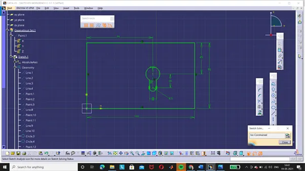
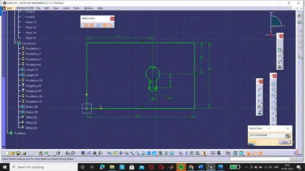
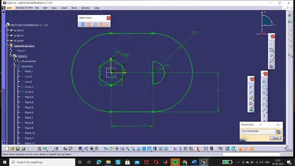
- Check for sketch solving status it must be iso-constrained.
- Now check for Sketch Analysis. There should be no warning and any sign of errors.
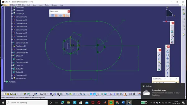
- The specification Tree is displayed on the left side of the screen while you are working.
- Provides access to the history of how a part was constructed and shows the product structure.
- Product entities can be selected from the specification tree or in the geometry area.
- Parts can be modified by selecting them from the Specification Tree.
- Solid parts are stored in the Part Body branch of the Part Tree.
- Save the 2D sketch by going to File-Save As with appropriate name.
NAVIGATION CONTROL IN CATIA:
- Click wheel and move mouse to PAN
- Click wheel and Right and move mouse to rotate.
- Click Wheel and right Release right and move mouse to Zoom.
SKETCH 1:
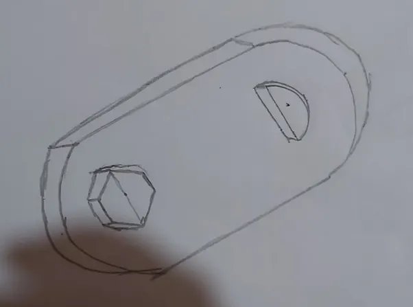
SKETCH 2:
SKETCH 3:
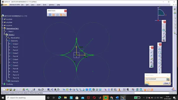
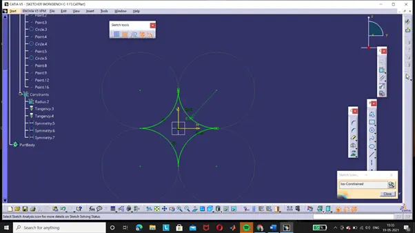
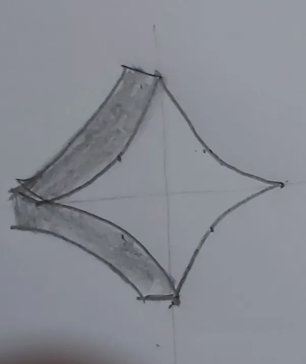
SKETCH 4:
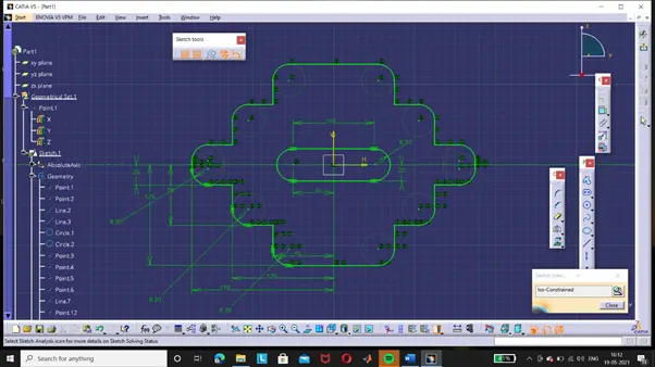
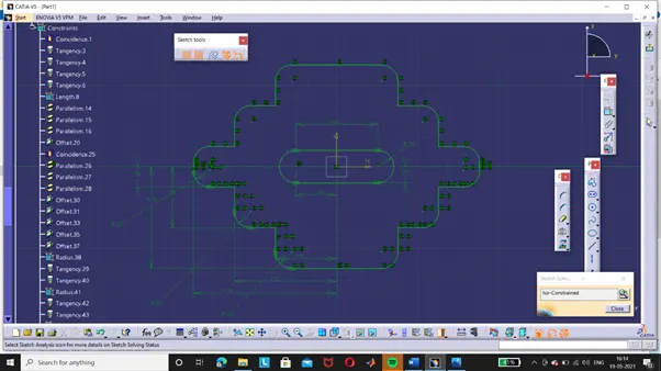
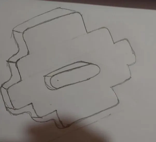
CONCLUSION: Hence, 2D Sketch drawn using Catia V5 Software.