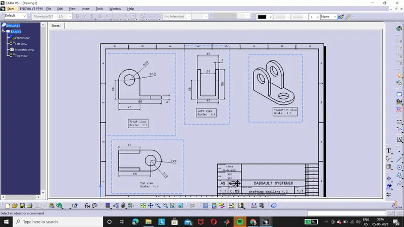
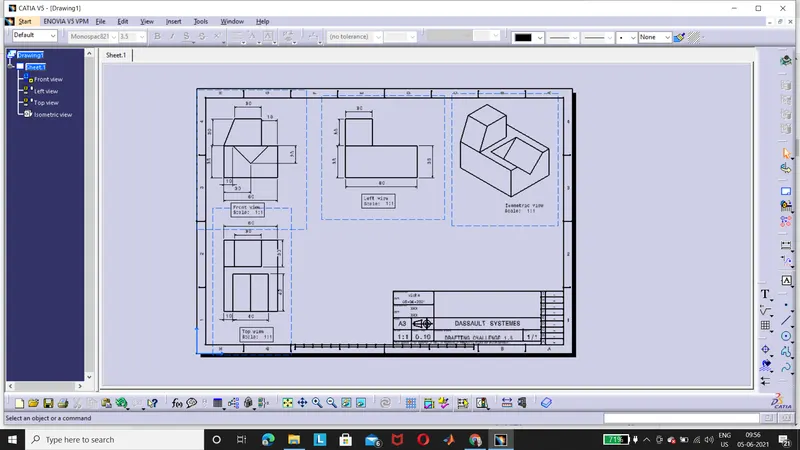
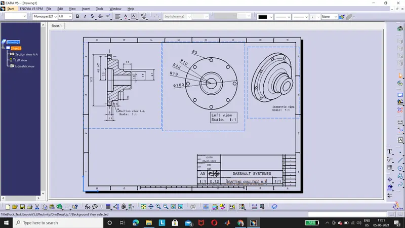
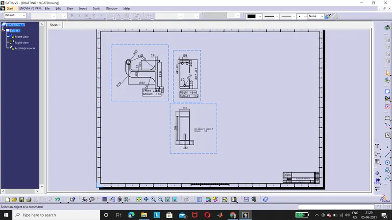
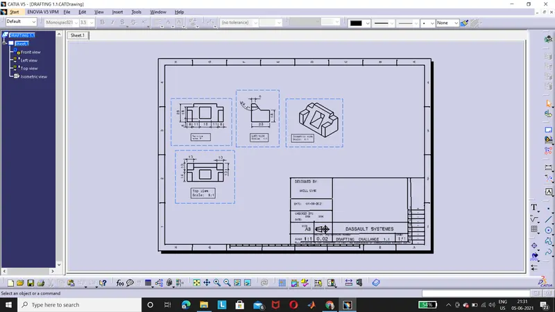
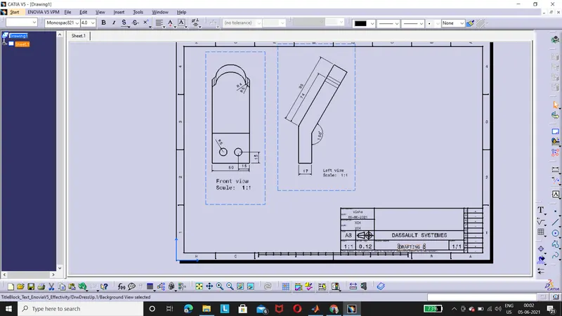
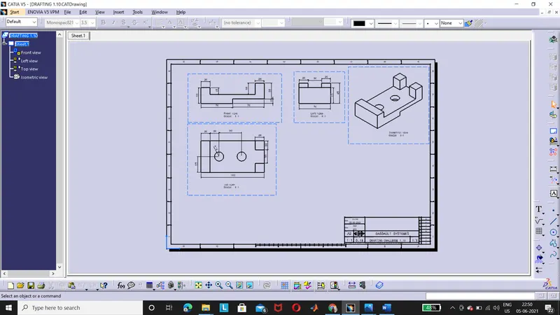
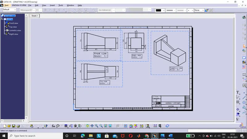
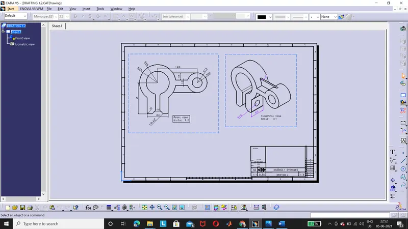
creating a 2D drawing from 3D Catpart in Drafting Workbench using catia V5 software
AIM: - To create a 2D from 3D Catpart in Drafting Workbench using catia V5 software
1.Generative Drafting workbench
The Generative Drafting workbench provides a simple method to create and modify views on a predefined sheet. You may also add, modify and/or delete dressup and 2D elements to these views. All this is performed on a sheet which may include a frame and a title block and will eventually be printed.
1.1 Creating a New Drawing
This task will show you how to create more or less automatically a new drawing with pre-defined views generated from a part. Select the Start -> Mechanical Design commands. Select the Drafting
dialog box appears with information on views that can possibly be created, as well as information on the drawing standards. Select the views you want to be automatically created on your drawing from the New Drawing Creation dialog box. Click OK.
1.2 Managing A Sheet
The Generative Drafting workbench provides a simple method for managing a sheet. A sheet contains: a main view: a view which supports the geometry directly created in the sheet, a background view: a view dedicated to frames and title blocks, interactive or generated views. Click
the New icon from the Standard toolbar or select File -> New… from the menu bar. Select the Drawing workbench, and click OK. From the New Drawing dialog box, select the ISO standard, or the A0 ISO format. Select the orientation type. Select the 1:1 scale, and then click OK.
1.3 Adding a new sheet
You can add new sheets at any time. These new sheets will be assigned the same standard, format and orientation as the sheet first created and defined using the New Drawing dialog (default setting). Even though you then delete sheet1, the sheets newly created will keep the same name.
Click the New Sheet icon from the Drawing toolbar. The new sheet automatically appears.
1.4 Front View Creation
The Generative Drafting workbench provides a simple method to create views on a predefined sheet. What is the Active View? The active view is the view from which other views will be generated. This is also the view in which all the modifications will be performed. The active view is framed in red. The non-active views are framed in blue. When you create a view, until you click at the desired view location, the view to be created is framed in green. If you click this view, it becomes the active view and is framed in red.
Start creating the front view. Click the Front View icon from the Views toolbar. Select object. Click on sheet to place front view. Blue arrows appear. Click the right or left arrow to visualize the right or left side, respectively. Click the bottom arrow to visualize the bottom side. Click the counterclockwise arrow to rotate the reference plane. Click inside the sheet to generate the view. Right-click the frame of the view, select the Properties option from the contextual menu, View tab and check the required options in the Properties dialog box.
1.5 2D/3D Associativity
On Views: A generative view results from specifications in a 3D document. This specification corresponds either to the whole document or to a feature in the document. Any modification applied to the specifications, before the generated view(s) is/are updated, is detected. You can
perform an update. You can update all views or a selection of views. The Update icon is active in the Update toolbar when a sheet (or drawing) contains views that need to be updated (this can be all views in the sheet or some of them only). You can update all views in the active sheet by
clicking this icon. An update symbol appears in the specification tree for the views that need to be updated. You can update a selection of views by selecting and right-clicking the view(s) you
want to update and choosing Update Selection from the contextual menu.
On Generated Dimensions: Generated dimensions are associative with the 3D part constraints on the condition you checked the Generation dimensions when updating the sheet option from the Options dialog box (Tools -> Options -> Mechanical Design -> Drafting -> Generation tab). Note that these dimensions will be re-generated in accordance with the other options checked/un-checked in the Options dialog box.
1.6 Creating a Projection View
This task will show you how to create projection views on the sheet, relatively to the front view
previously generated. Click the Drawing window, and double-click the Projection View icon from the Views toolbar (Projections subtoolbar). As you move the cursor, a previewed projection view in a green frame appears on the sheet. Define the projection view position by positioning the cursor at the desired view location, for example the right view position. Click inside the green frame to generate the view.
1.7 Creating an Auxiliary View
This task will show you how to create an auxiliary view. Many objects are of such shape that their principal faces cannot always be assumed parallel to the regular planes of projection. Creating an auxiliary view allows showing the true shapes by assuming a direction of sight perpendicular to planes that are perpendicular of the curves. This auxiliary view, together with the top view,
completely describes the object. Click the Auxiliary View icon from the Views toolbar (Projections subtoolbar).
Click an edge on the view. The selected edge becomes a line that you can position where desired using the cursor. This line/callout will be automatically used as the plane. Click to position the callout. The reference plane is automatically positioned according to the selected edge. Positioning the auxiliary view callout amounts to defining the auxiliary view direction. Click to position the auxiliary view.
1.8 Creating an Offset Section View / Cut
This task will show you how to create an offset section view/cut using a cutting profile as cutting plane. In sectioning through irregular objects, it is often desirable to show several features that do not lie in a straight line by offsetting or bending the cutting plane. Click the Drawing window, and
click the Offset Section View icon or the Offset Section Cut icon from the Views toolbar (Sections subtoolbar). Select the holes and points required for sketching the cutting profile. If you
are not satisfied with the profile you create, you can, at any time, use Undo or Redo icons. The section plane appears on the 3D part and moves dynamically on the part. Double-click to end
the cutting profile creation. OFFSET SECTION CUT: In this particular case, only cut portion of solid is visible in section view.
1.9 Creating an Aligned Section View / Cut
This task will show you how to create an aligned section view and/or aligned section cut using a cutting profile as cutting plane. An aligned section view / cut is a view created from a cutting profile defined from non-parallel planes. In order to include in a section certain angled elements, the cutting plane may be bent so as to pass through those features. The plane and feature are then imagined to be revolved into the original plane. Click the Drawing window, and click the Aligned
Section Cut . Select the points and circles required for sketching the cutting profile. The section plane also appears on the 3D part and moves dynamically on the part. Double-click to end the cutting profile creation. Click to generate the view.
1.10 Creating a Detail View / Detail View Profile
A detail view is a partial generated view that shows only what is necessary in the clear description of the object. It shows you how to create from the 3D a detail view using either a circle as callout or a sketched profile. In this particular case, we create a detail view using a sketched profile as we create this detail view from an oblong part. Note that for creating a detail view using a circle, the
dialog is exactly the same. Click the Drawing window, and click the Detail View icon from the Views toolbar (Details subtoolbar). Click the callout center. Drag to select the callout radius and click a point to terminate the selection. Or, if you create a detail view using a sketched profile, you
will click the Detail View Profile icon . Create the points required for sketching a polygon used as profile. Double click to end the cutting profile creation. Click to generate the detail view. The default scale is 2 (twice the scale of the active view). You can modify this scale.
1.11 Creating a Clipping View and/or a Clipping View Profile
A clipping view is a partial view that shows only what is necessary in the clear description of the object. This operation is applied directly onto the active view. Here we will see how to create both a clipping view using a circle as callout. You can also use a roughly sketched profile. Click
the Drawing window, and click the Clipping View icon from the Views toolbar (Clippings subtoolbar). If you create a clipping view using a sketched profile, you will select the Clipping
Profile View icon . Select the center of the circle or select the required points for sketching a polygon. Double-click to end the cutting profile creation.
1.12 Creating an Isometric View
To produce an isometric projection, it is necessary to place the object so that its principal edges make equal angles with the plane of projection and are therefore foreshortened equally. Click the
Drawing window, and click the Isometric View icon from the Views toolbar (Projections 86
subtoolbar). Click the 3D part. A green frame with the preview of the isometric view to be created, as well as blue manipulators appear. You can re-define the view to be created position using these manipulators: to the bottom, the left, the right, the top, or rotated using a given snapping or according to an edited rotation angle.
Dimension Creation
You can customize given options when creating or re-positioning dimensions. Select the Dimension tab in Options.Dimension Creation: Dimension following the mouse (ctrl toggles): you can decide that the dimension line is positioned according to the cursor, following it dynamically during the creation process. Constant offset between dimension line and geometry: the distance between the created dimension and the geometry remains the same when you move the geometry. Default dimension line/geometry distance: if you position the dimension according to the cursor, you can define the value at which the dimension is created. If you create associativity between the dimension and the geometry, you can define the value at which the dimension will remain positioned. If you click the Associativity on 3D switch button the following dialog box appears: A link can be applied between a dimension and the 3D part. As a result, when you update the drawing, the dimension is automatically re-computed. Create driving dimensions: the dimension you will create will drive the geometry.
Move: The Configure switch button allows you to choose either the dimension to be snapped on the grid or/and the dimension value to be located at its default position between symbols (it will work only if the cursor is between the symbols). Line-Up: You can organize dimensions into a system with a linear offset. The offset will align the dimensions to each other as well as the smallest dimension to the reference element. Analysis Display Mode: Colors can be customized with the Activate analysis display mode option. To activate this mode, select this option and then click the Types and colors button. The Types and colors of dimensions dialog box lets you assign the desired color(s) to the selected dimension types.
Figures:-