Creating the Solid CATpart from 2D drawings
AIM: To create a 3D or Part body in Part workbench and to use Sketch based and Dress-up Features on the same using Catia V5 Software.
PROCEDURE FOR CREATING A SKITCH :
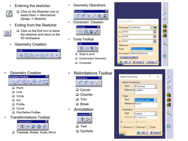
- Open Catia V5 software and go to File-New-Part (Select: Create a geometrical set)
- Create a point at the centre axis with co-ordinates X=0, Y=0 & Z=0.
- Go to Toolbar-Insert-Sketcher -Positioned sketch.
- In Sketcher Positioning select YZ-plane and in projecting point select centre point of the origin.
- Sketch the geometry with Profile toolbar.
- Profile Toolbar: The commands located in this toolbar allows you to create simple geometries (rectangle, circle, line etc.) and more complex geometries (profile, spline etc.)
- Operation Toolbar: Once a profile is created, it can be modified using commands such as trim, mirror, chamfer etc.
- Constraint Toolbar: Profiles may be constrained with dimensional (distances, angles, radius, tangents etc.)
- Check for sketch solving status it must be iso-constrained.
- Now check for Sketch Analysis. There should be no warning and any sign of errors.
- The specification Tree is displayed on the left side of the screen while you are working.
- Provides access to the history of how a part was constructed and shows the product structure.
- Product entities can be selected from the specification tree or in the geometry area.
- Parts can be modified by selecting them from the Specification Tree.
- Solid parts are stored in the Part Body branch of the Part Tree.
- Save the 2D sketch by going to File-Save As with appropriate name.
NAVIGATION CONTROL IN CATIA:
- Click wheel and move mouse to PAN
- Click wheel and Right and move mouse to rotate.
- Click Wheel and right Release right and move mouse to Zoom.
SKETCH-BASED FEATURES IN CATIA: -
Create a Pad: Click this icon, select the profile to be extruded and enter the parameters you need in the dialog box.
Using the Sub-elements of a Sketch: right-click the Selection field from the Pad or Pocket dialog box and select Go to Profile Definition to display the Profile Definition dialog box.
Create an ‘Up to Next’ Pad: Click this icon, select the profile to be extruded, set the Type option to Up to next and enter the parameters you need in the dialog box.
Create an ‘Up to Last’ Pad: Click this icon, select the profile to be extruded, set the Type option to Up to last and enter the parameters you need in the dialog box.
Create an ‘Up to Plane’ Pad: Click this icon, select the profile to be extruded, enter the parameters you need, set the Type option to `Up to plane‘ in the dialog box and select the required plane.
Create an ‘Up to Surface’ Pad: Click this icon, select the profile to be extruded, enter the parameters you need, set the Type option to Up to surface in the dialog box and select the required surface.
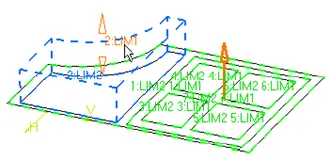
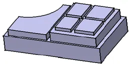
Create a Pocket: Click this icon, select the profile and enter the parameters you need in the dialog box.
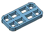
DRESS-UP FEATURES: - Dressing up features is done by applying commands to one or more supports.
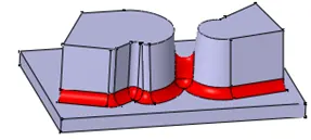
A fillet is a curved face of a constant or variable radius that is tangent to, and that joins, two surfaces. Together, these three surfaces form either an inside corner or an outside corner. In drafting terminology, the curved surface of an outside corner is generally called a round and that of an inside corner is normally referred to as a fillet. Edge fillets are smooth transitional surfaces between two adjacent faces.
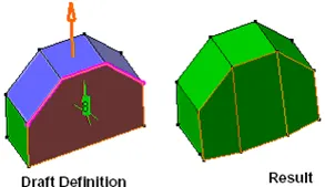
Chamfer Chamfering consists in removing or adding a flat section from a selected edge to create a beveled surface between the two original faces common to that edge. You obtain a chamfer by propagation along one or several edges.
SCREEN SHOTS OF FEATURES USED ON THE PART BODY:-
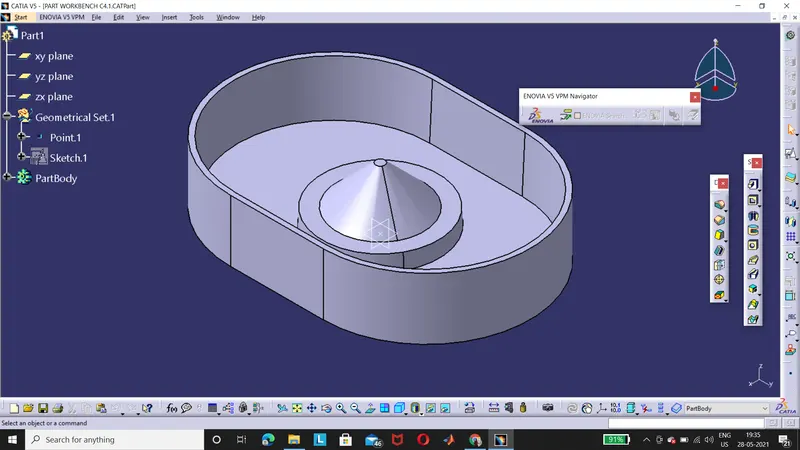
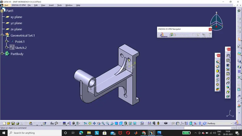
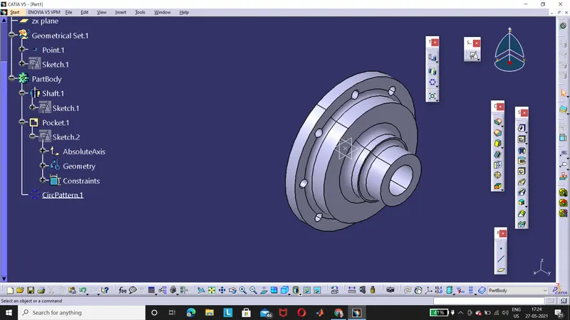
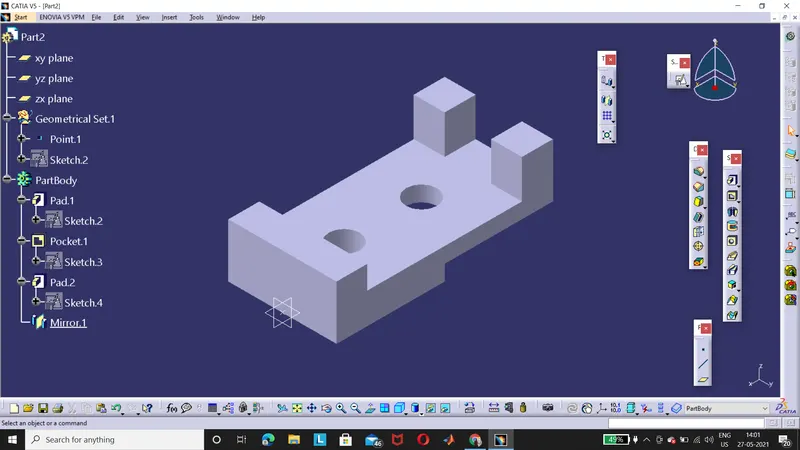
CONCLUSION: - Hence shown the Sketch based and Dress-up features on the 3D body part workbench using Catia V5 software.