Week 8 - Challenge 1 - Draft Analysis on a Fan Cover
OBJECTIVE: - Creating the tooling axis for the given Fan Cover model by meeting the requirements of the draft angle and performing the Draft analysis on the model.
DETAILED REPORT:
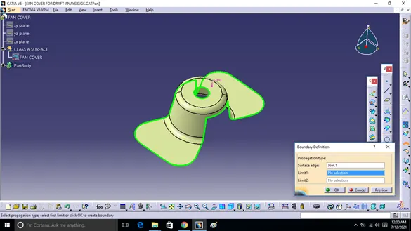
- Checking the continuity of given class A surface: This is to ensure that no discontinuities are present in the given class A surface. This can be ensured by using Join or boundary command in CATIA. If no discontinuities are in Class A surface then boundary will be highlighted with green color as shown below.

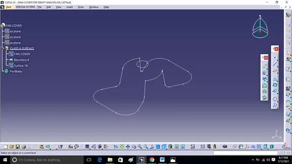
- Continuity of the Class A surface can also be ensured by extracting the boundary of given Class A surface as shown below.
2.Tooling axis direction: It is a direction in which mould or core and cavity opens it can be decided by visually analyzing the model as shown below.
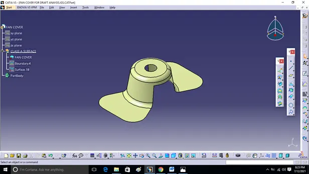
- From X direction as tooling axis we can say that we require side core for top hole which increases mould cost so X direction for tooling axis is not preferable.
- From Y direction as tooling axis we require side core for top hole which increases mould cost so Y direction for tooling axis is not preferable.
- So Z direction as tooling axis we clear this hole in tooling so Z direction is preferable as tooling axis.
- Now we will use bisecting method to find out real tooling axis.
- Insert axis system. Taking intersection of ZX plane with class A surface. We will get two curves.
- Now we will use bisecting method to find out real tooling axis
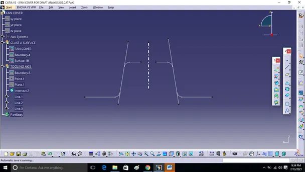
- Creating axis system and taking intersection of ZX plane with class A surface then two curves get generated.
- Now we have to check which surface will create problem or will be difficult for tooling. Because the surface which 90o to tooling axis will be cleared. So we have to check the surface which will lie parallel to tooling axis direction. Make a line along parallel surface using point and direction. Here we get two lines, now we will bisect the two lines and choose vertical direction. This will be our tooling axis for X-direction.
- Similarly we intersect the YZ plane of the axis system with the class A surface& repeat the same procedure again.
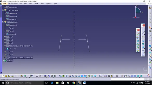
- Now we have two axis e. Tooling clearing X & Y axis. We will bisect these two axis to get our final tooling axis.
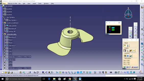
DRAFT ANALYSIS: -
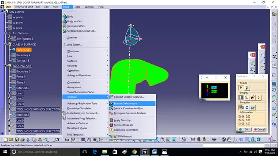
1.To perform draft analysis. Go to insert<Analysis<Feature draft analysis.
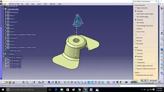
2.Before that switch customize view parameter mode to material.
3.Click on compass icon & align it with the main tooling axis & click on the surface, we will get our results
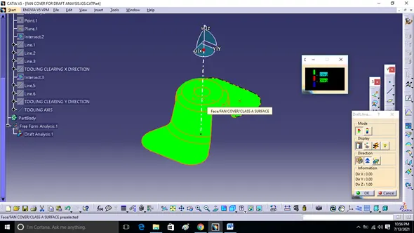
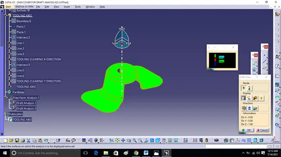
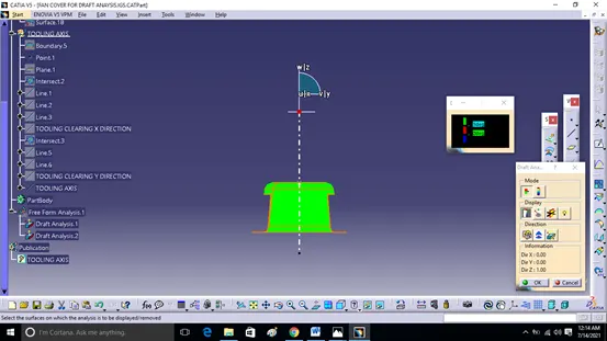
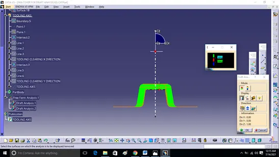
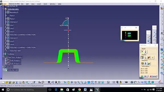
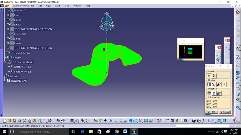
- From the above image it is seen that surface in green colour has more than 3 degree draft which is most required for tooling feasibility.
- By inversing draft direction we get below image.
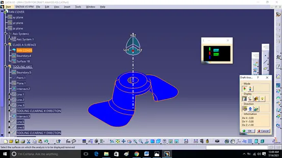
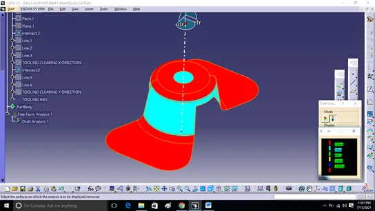
- Below image shows full draft analysis.
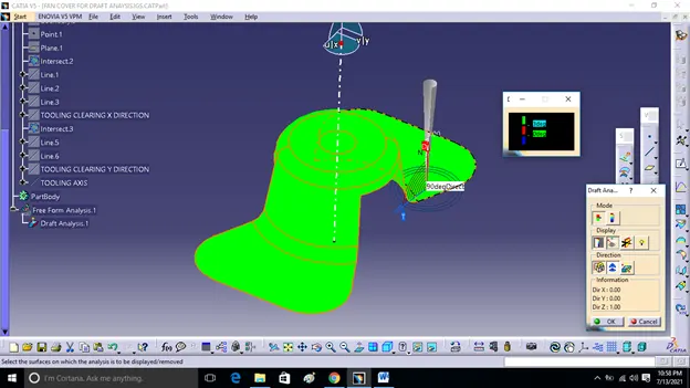
- We also check the draft angle of running point on surface.
- Image of the model with the proper color code of the draft angle in various orientations (Isometric, Front, side and Top view)
ISOMETRIC view: -
FRONT VIEW:
LEFT SIDE VIEW:
RIGHT SIDE VIEW:
TOP VIEW:
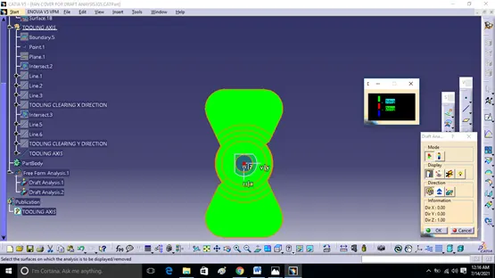
- Image of the tree structure, geometrical set of tooling axis & publications.
CONCLUSION: - Hence the tooling axis has been created for the given Fan cover which is meeting the requirement of draft angle and Draft analysis done on the model.