Creating 3D Isometric view of various structural elements in AutoCAD
1.ANSWER
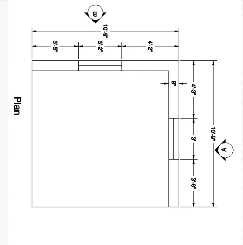
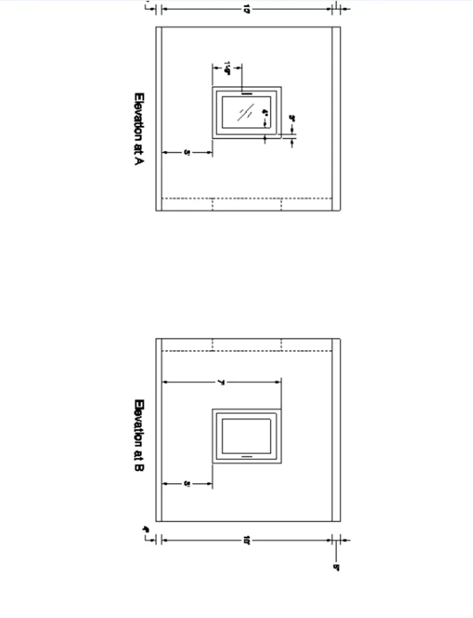
AIM: Create a 3D Isometric View of the building with plan and elevation given.
PROCEDURE:
Open new sheet and change the Units from metric to engineering precision 0’-0” ENTER.
- Using commands for creating the isometric view of the building plan and elevations are,
- Line
- Rectangle
- Copy
- Offset
- Join
- Boundary
- Extrude
- Presspull
- Union
- UCS
- 3Drotate
- Create the plan with Line command in top view in 2d wireframe.
- Using Join command for make all lines converts into polyline.
- Then change the view to isometric by using the corner of WCS icon.
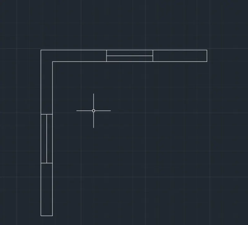
Then use boundary by typing BOUNDARY in the command prompt.
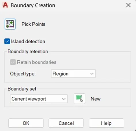
- Specify the required closed portion make it into a region.
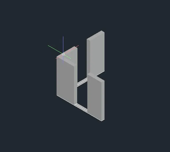
- Then Extrude the required portion at the height of 10’-0” ENTER.
- Using Rectangle from taking in the ribbon.
- Type UCS in the command prompt and click on the face option for creating windows at required face.
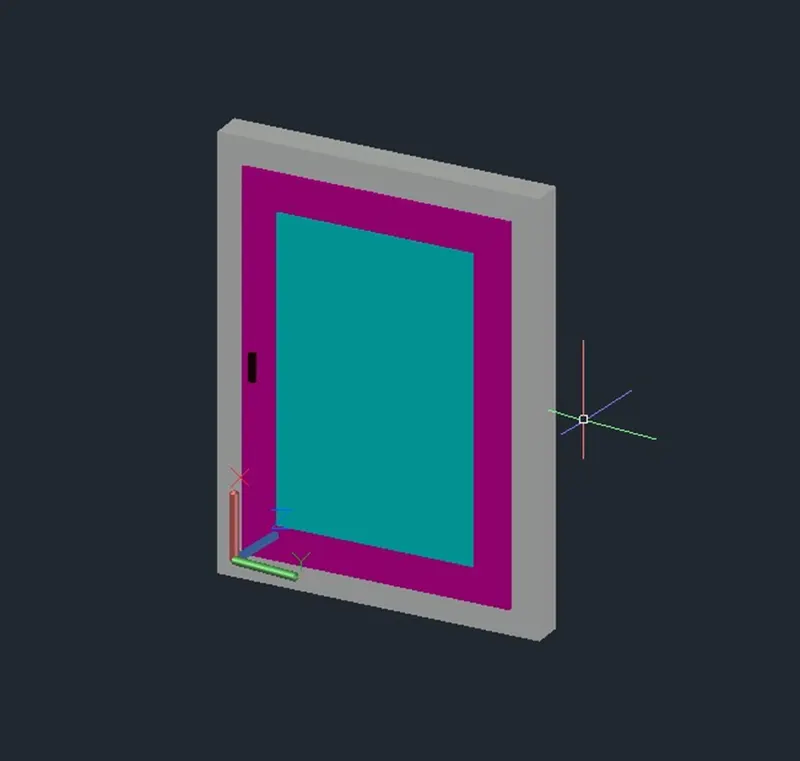
- Create a window with given dimensions and apply some layers for more clarity.
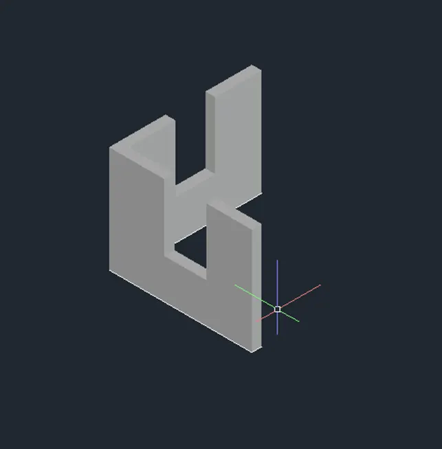
- Create a required window opening by using Rectangle and Extrude commands.
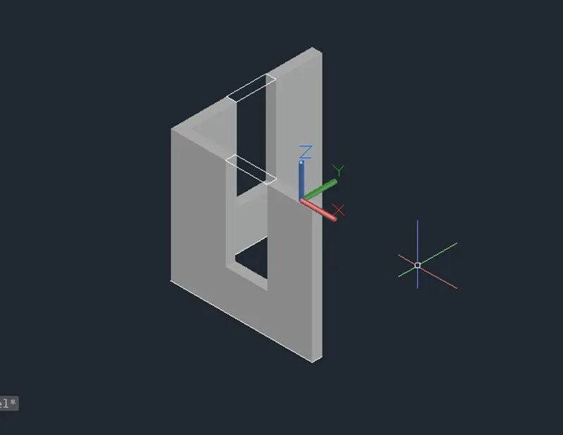
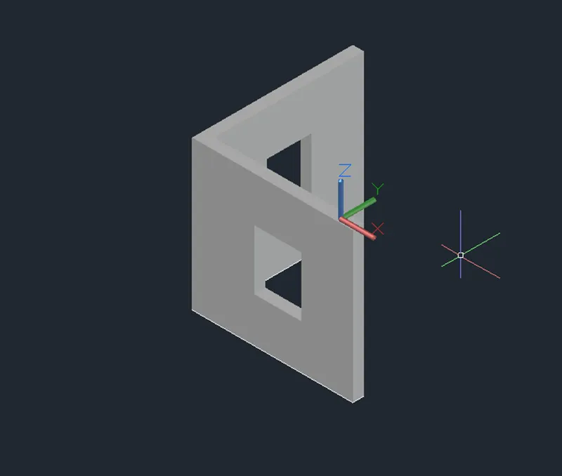
- Assigning the material properties to the windows.
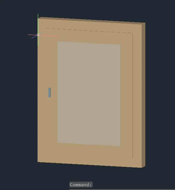
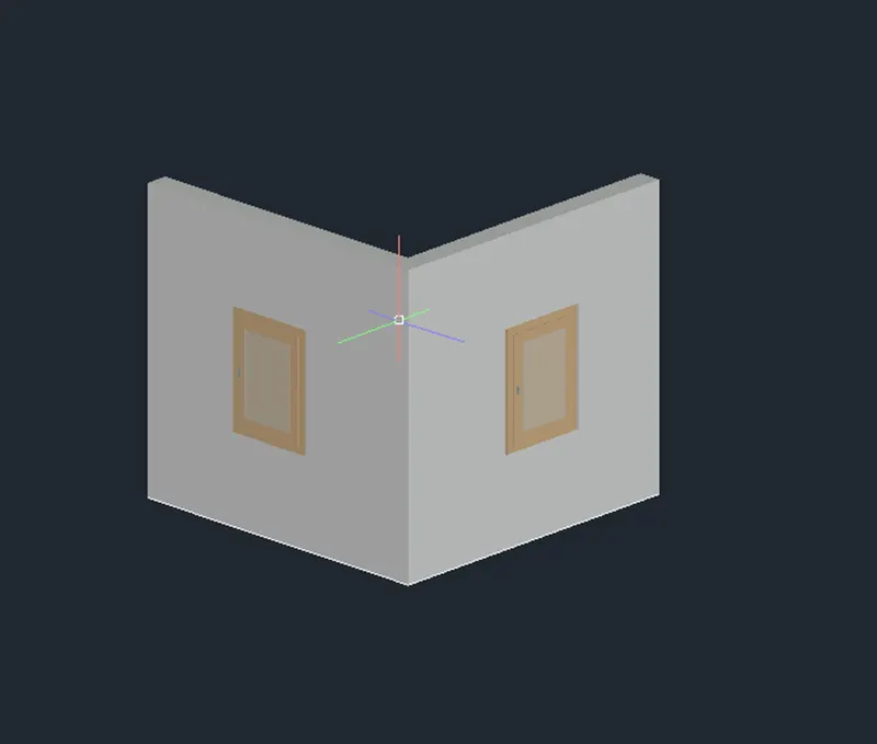
RESULT:
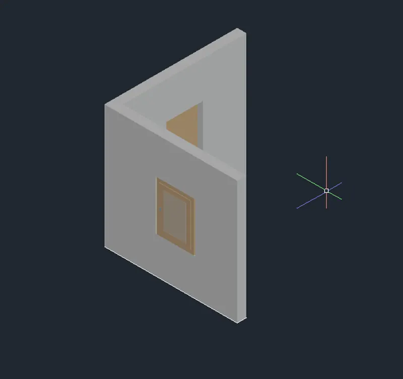
2.ANSWER
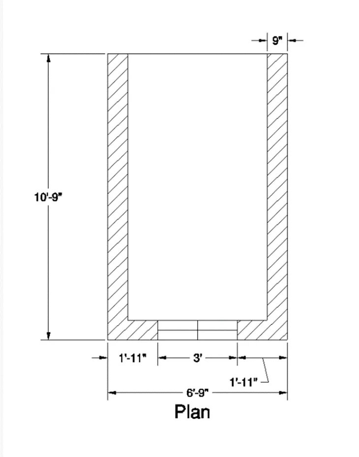
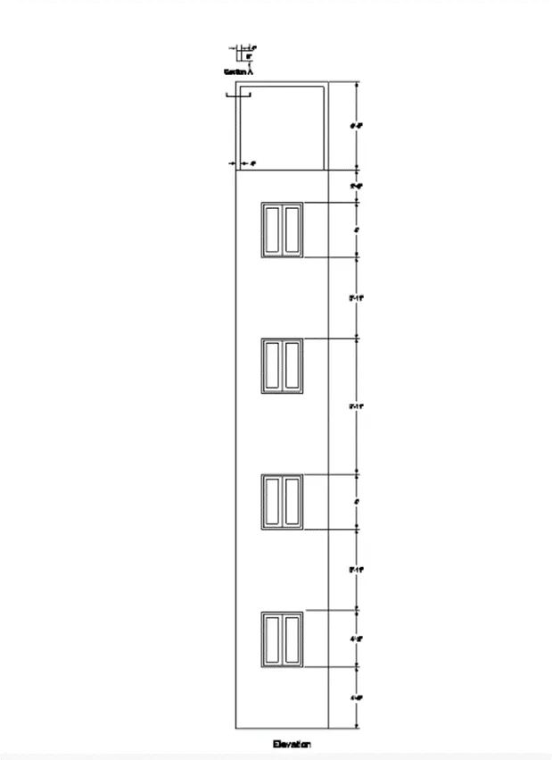
AIM: Create the 3D View of the Building Façade as given in the plan and elevation. Also, see the detail of the window.
PROCEDURE:
- Using Line and Rectangle command to create the plan in the top view in 2D wireframe with given dimensions.
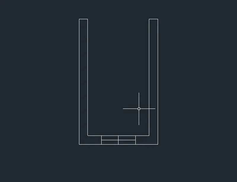
- Then apply the region by Boundary by typing Boundary in the command prompt.
- Select a pick point and make it a region.
- After applying the region this the top view in shaded view.
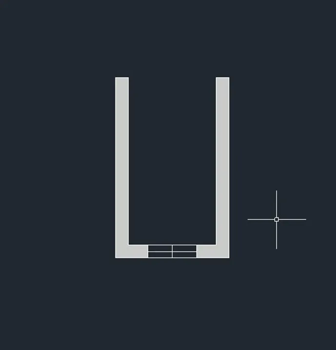
- Then change the view from top view to isometric.
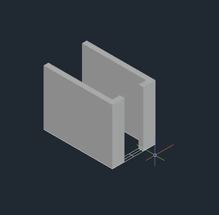
- Create the window as per given dimensions.
- Using rectangle by typing REC in the command prompt.
- Create a rectangle at the window opening.
- Then increase the height of the wall by using extrude command at the height of 3’-0”.
- Using UCS for work on required face
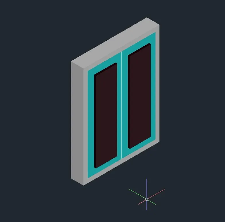
- Here iam using different layers to identify it better.
- Then apply the material properties to different materials.
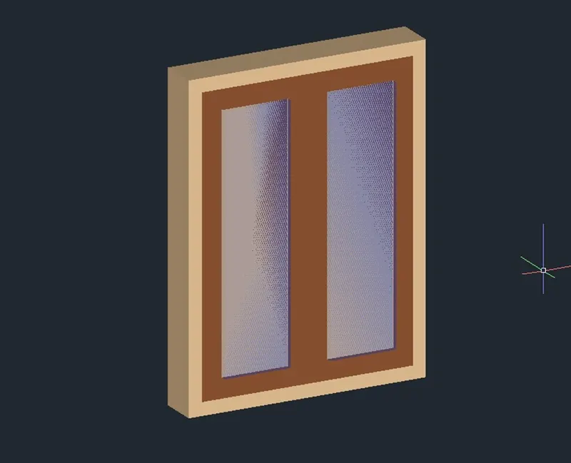
- Then using Move command to move the window at the opening I created.
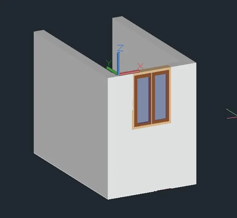
- Then Using a Press Pull command for extend the wall.

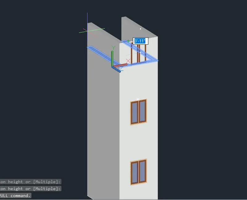
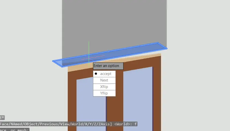
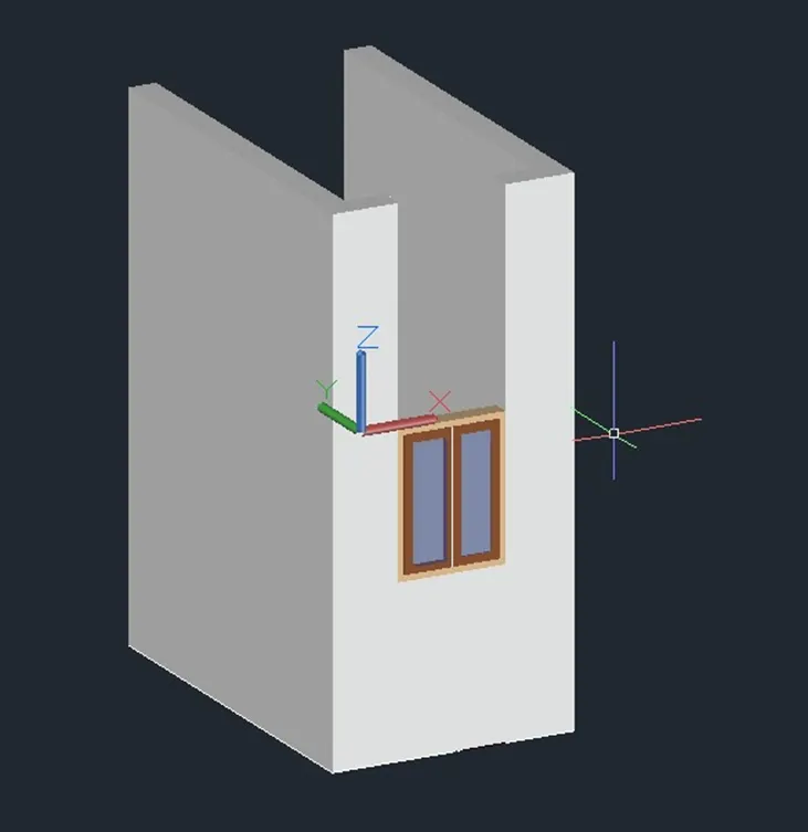
- Repeat the same process until create the elevation as given figure.
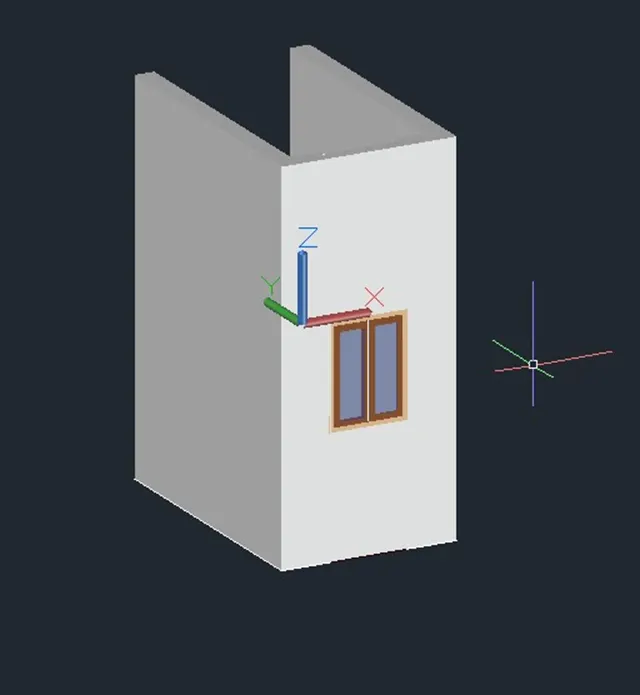
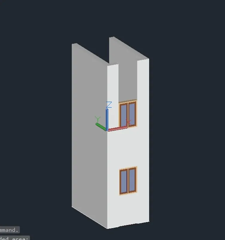
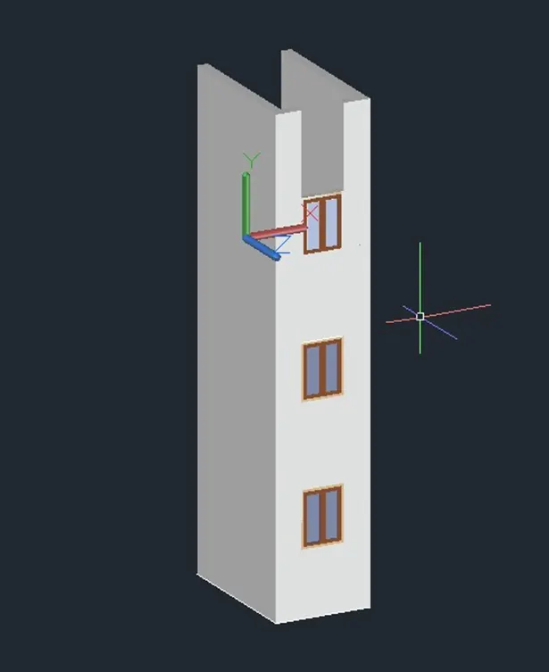
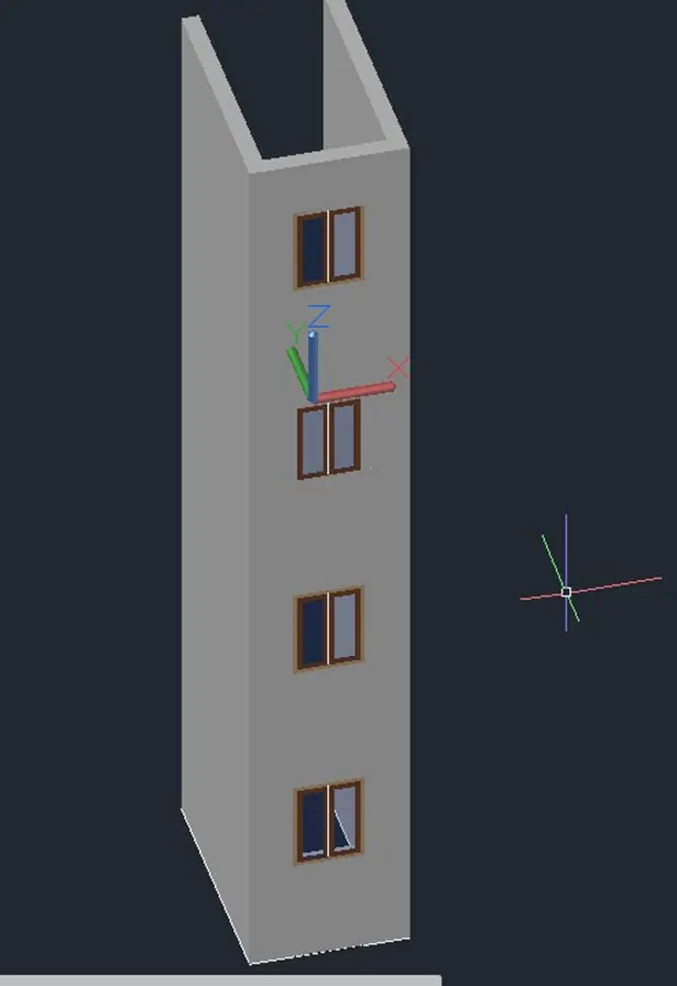
RESULT:
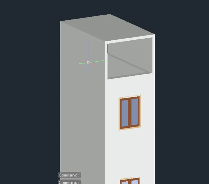
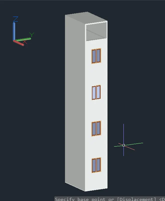
3.ANSWER
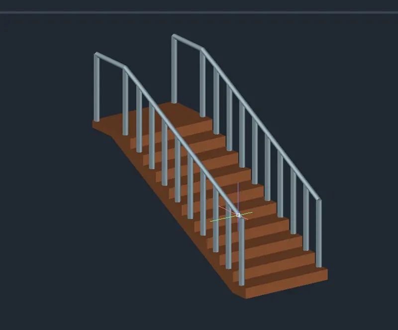
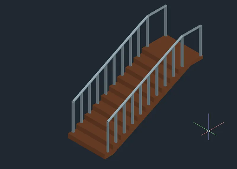
AIM: Create the isometric 3d view of a stair with railing as shown in the plan and elevation. Assume the size of the balustrades and the hand rails.
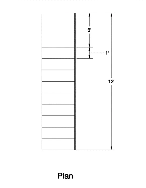
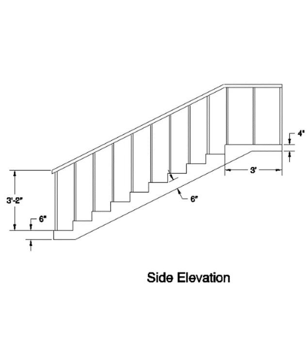
PROCEDURE:
- Using Line command for create the side face of the elevation in isometric view.
- Using Join command for join the all lines make it into polyline.
- Apply the region for make it into solid.
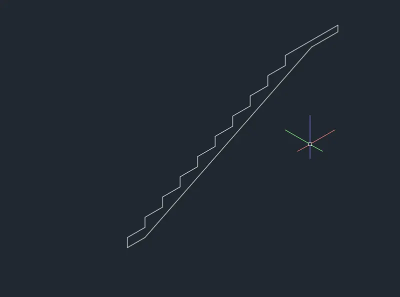
- Using extrude command to create the elevation.
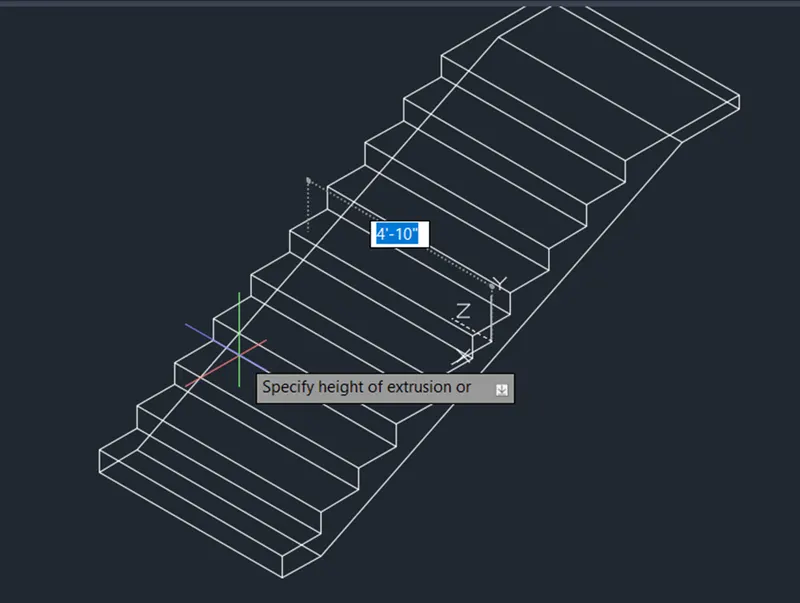
- View in a 3D shaded.
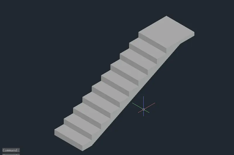
- Then using circle to create the railing.
- Using UCS command to work on a required face.
- Extrude the circle to 3’-2” height.
- Using Copy command to copy the cylinders to required positions.
- After creating the railing bars Using 3DPOLY for connects the mid points of the to the cylinder
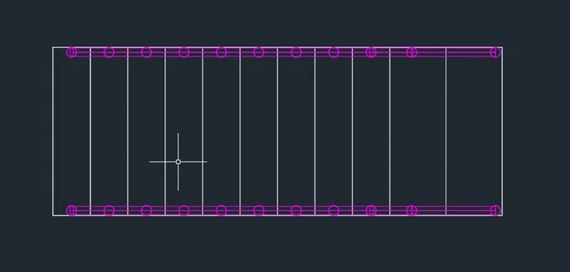
Then create a circle and make it Sweep by path line.
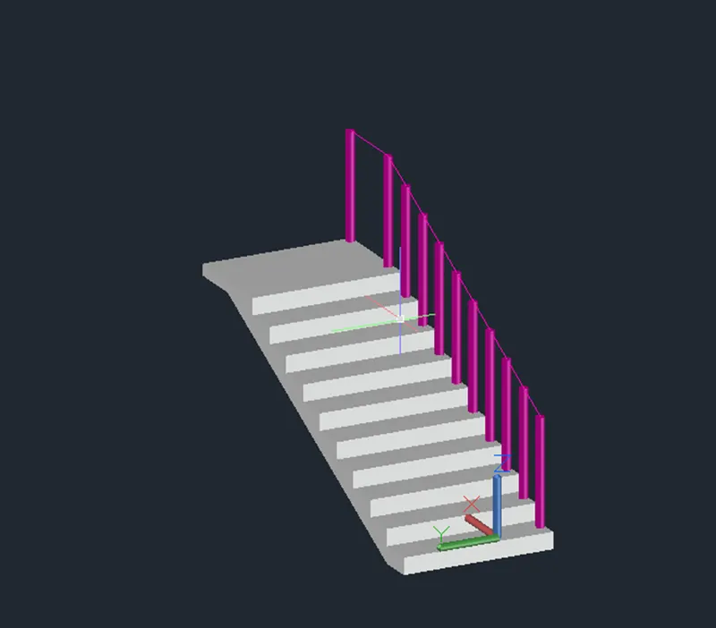
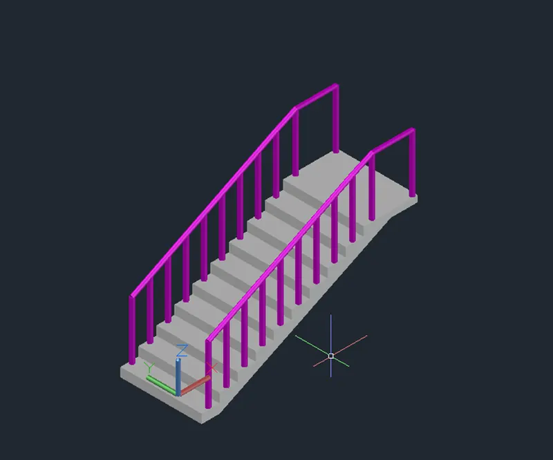
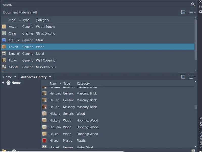
After assigning the material properties.
RESULT:
4.ANSWER
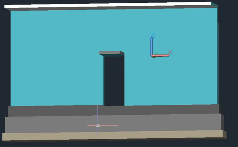
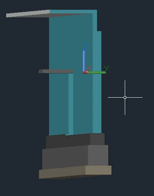
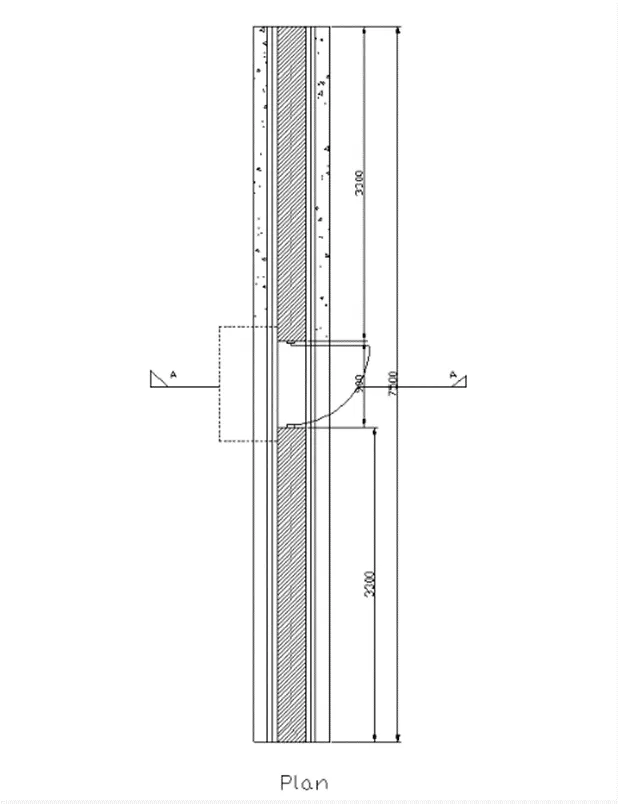
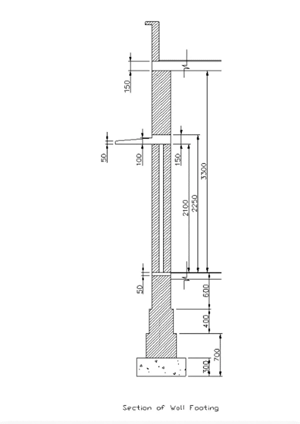
AIM: Create the 3D view of a Wall with spread footing. Create the Door opening only. Assume the size of the parapet and the coping. See the plans and elevation for the details. Also, create a rendered view of the model with materials as of your choice.
PROCEDURE:
Change the units engineering to metric and precision 0 ENTER.
- Using Rectangle, Move, Line Extrude, Press pull, Union, Subtract and Region commands to create the spread footing.
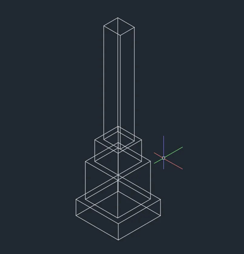
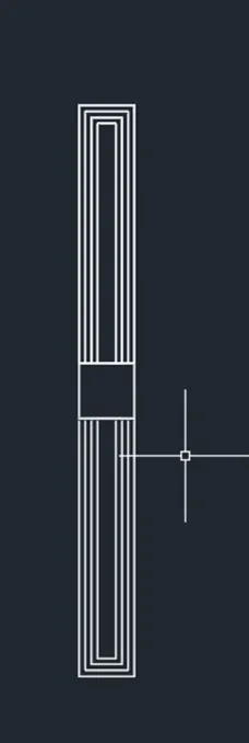
- Top view of the spread footing after creating by using rectangle, line, extrude, region etc.
- View of isometric in 2d wireframe.
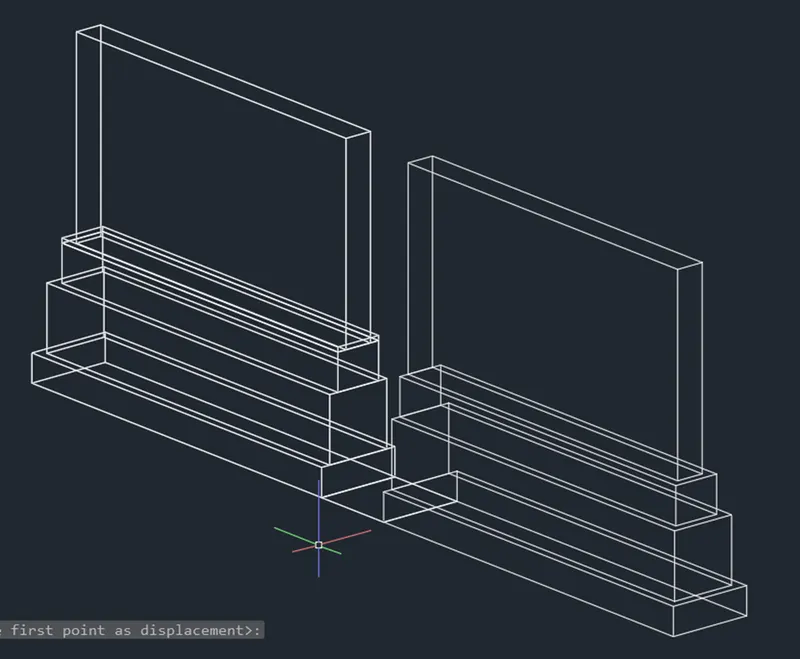
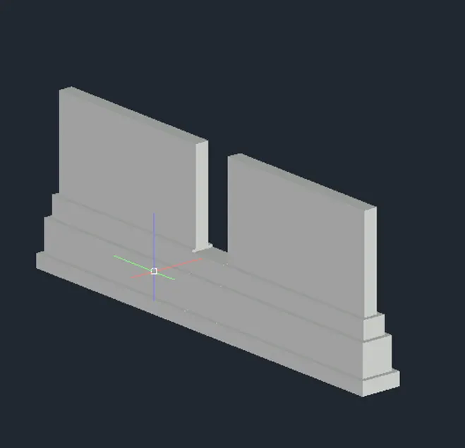
- Using UCS command for work on required faces.
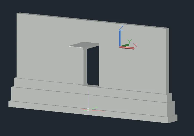
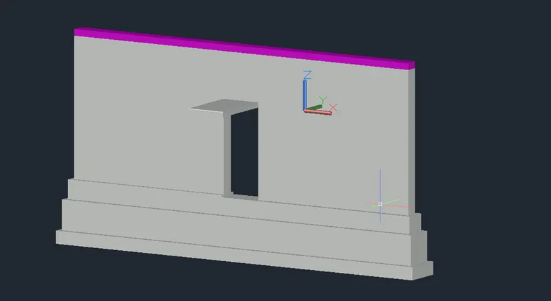
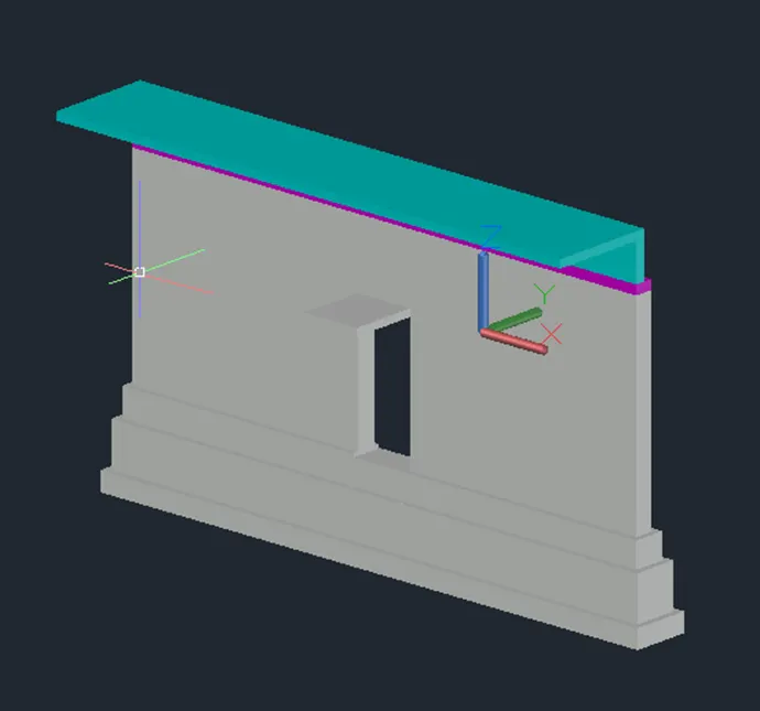
- After creating the 3D view of wall with spread footing.
- Assign the material properties from visualization tab.
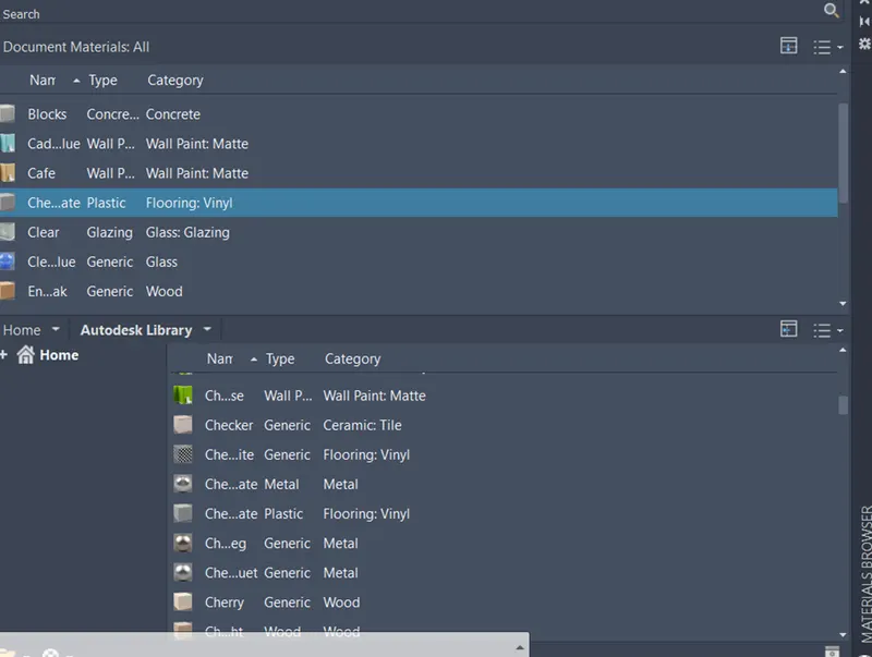
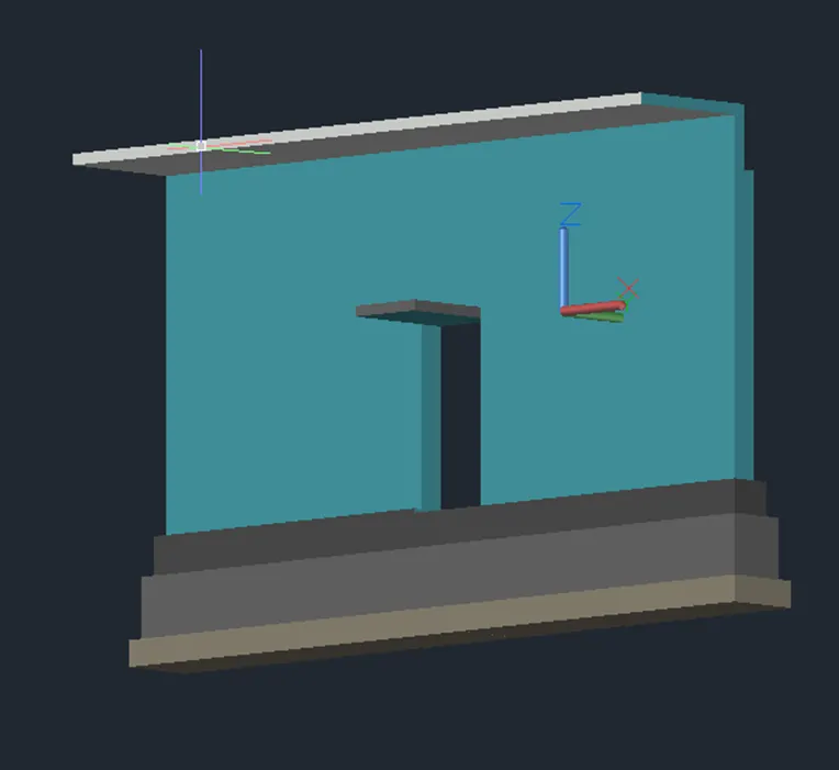
RESULT: