Project 2_Creating a 3D rendered model for a Residential Building in AutoCad
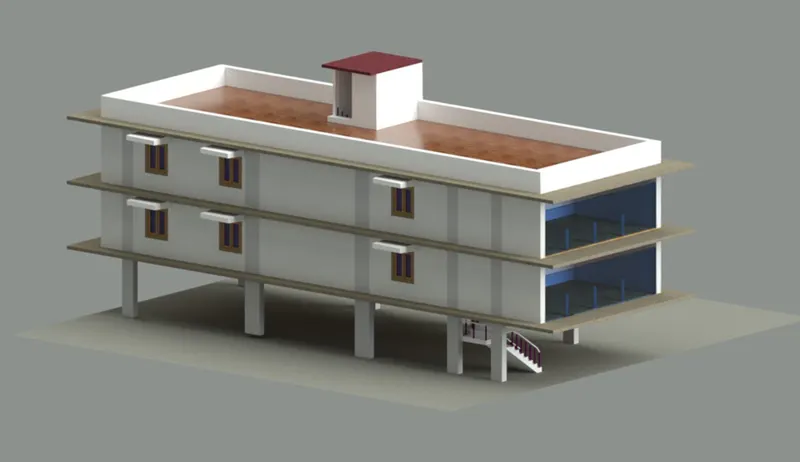
PROJECT 2 : Creating a 3D rendered model for a residential building in Autocad.
AIM : To draw the 3D residential building and create the rendered view.
PROCEDURE:
Here iam taking week 8 challenge project 1 layout for creating 3D rendered view.
The general commands used for creating the elements are as follows:
- Line
- Rectangle
- Copy
- Move
- Erase
- Offset
- Trim
- Rotate
- 3Dorbite
- 3Drotate
- Extrude
- Presspull
- Fillet
- Mirror
Etc.
Open the new file and copy and insert the week 8 project1 layout in the new sheet.
Made some changes in the plan.
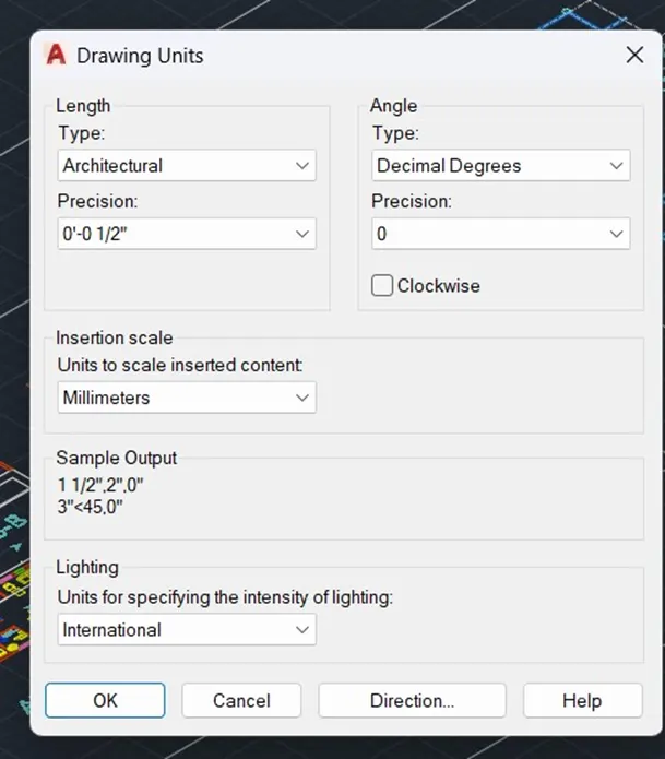
Change the units metric to architecture and precision as 0’-0” ENTER.
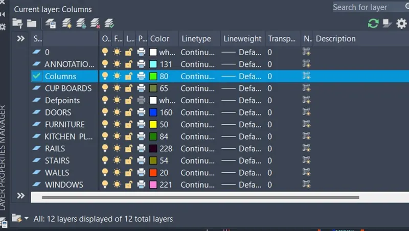
- Assigning different layer properties to the different elements.
- Creating ground floor layout for parking area and future expansion purpose.
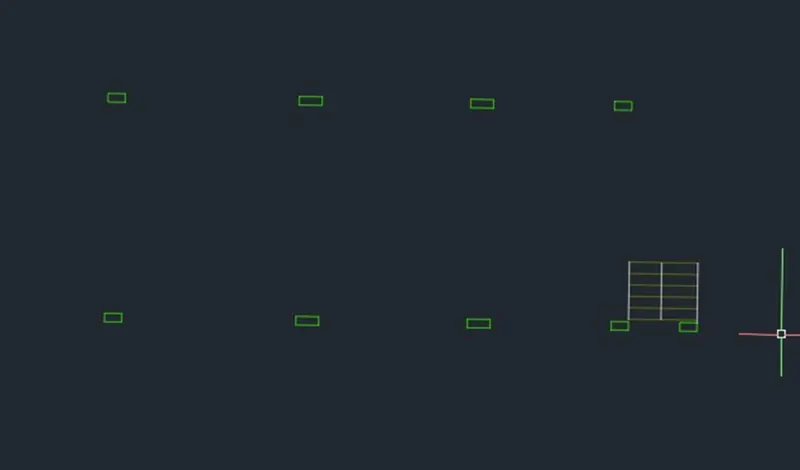
- Apply the region to the columns.
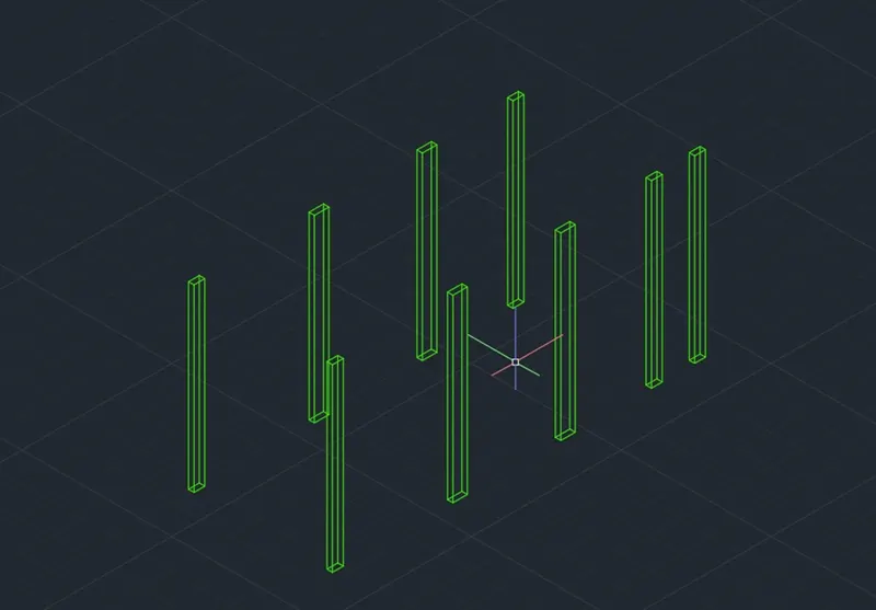
- Extrude it at specified height by typing EXT in the command prompt ENTER.
The required dimensions are,
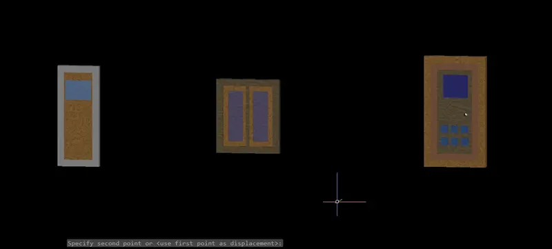
- Door1 = 3’- 4” X 6’- 11”
- Door2 = 2’- 9” X 5’- 11”
- Window= 3’- 2” X 4’- 2”
Dimensions of the rooms,
- Bed Room 1 = 13’-6” X 9’ -1”
- Bed Room 2 = 13’-6” X 9’ -1”
- Staircase = 6’-0” X 7’-5”
- Toilet 1 = 6’-2” X 9’ -1”
- Common washroom = 6’-2” X 6’-0”
- Dinning area = 16’-6” X 7’- 6”
- Living room area = 20’ – 6” X 9’ – 10”.
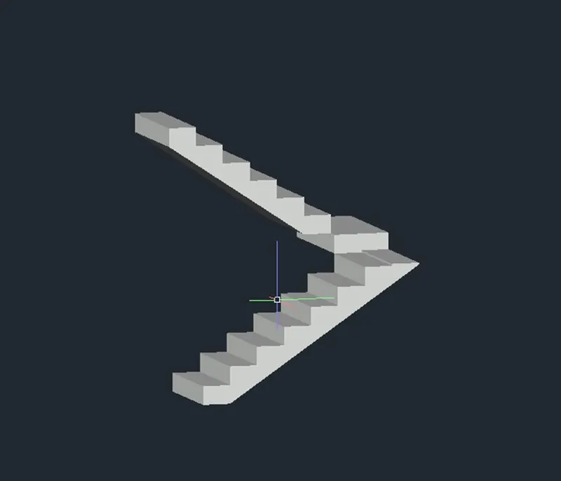
Creating a staircase by using Line command. Rise 6” and treads 6.
Using Join command by typing J in the command prompt to make them in a polyline.
After creating the face of the stairs extrude 3’ by using EXT ENTER.
Copy the created staircase for another flight.
Using 3Drotate command to rotate the staircase for required position.
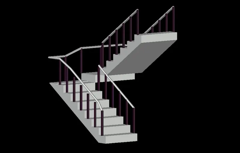
- Create rail by using Circle command with radius 2” enter.
- Extrude the circle at the height of 3’ ENTER.
- Copy them at each tread by using Copy command.
- Then Using 3DPOLY for creating handrail select at the top of the railing.
- Create a circle with 2” diameter and use a command Sweep and select a object then show the polyline as a path.
First floor Layout
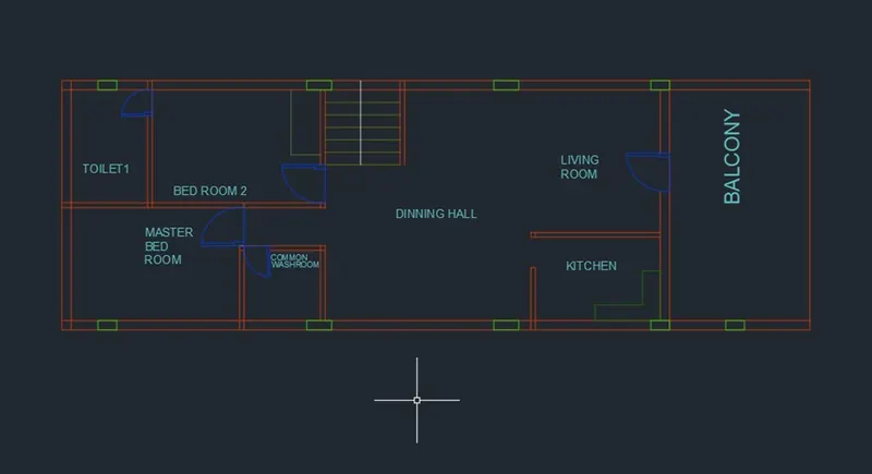
- The external walls are 9” and interior walls are 4.5”.
- Using a Boundary command to create a wall in a 3D model.
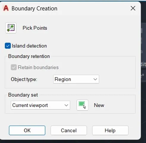
Join the all lines before picking the internal portion of the wall.
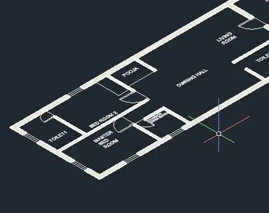
Then extrude the walls at required height by typing EXT in the command prompt.
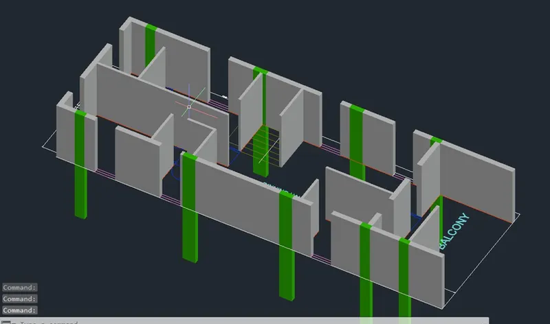
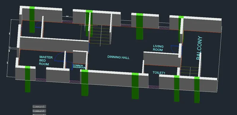
- Create the doors and windows at the openings.
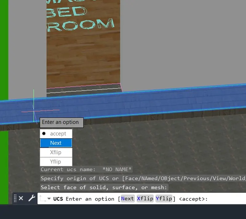
- Using UCS command to work on the required face.
- Top view of the first floor plan layout.
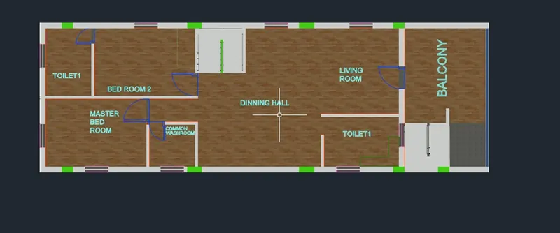
- Add the Floor sheet by using rectangle command and using extrude with floor thickness.
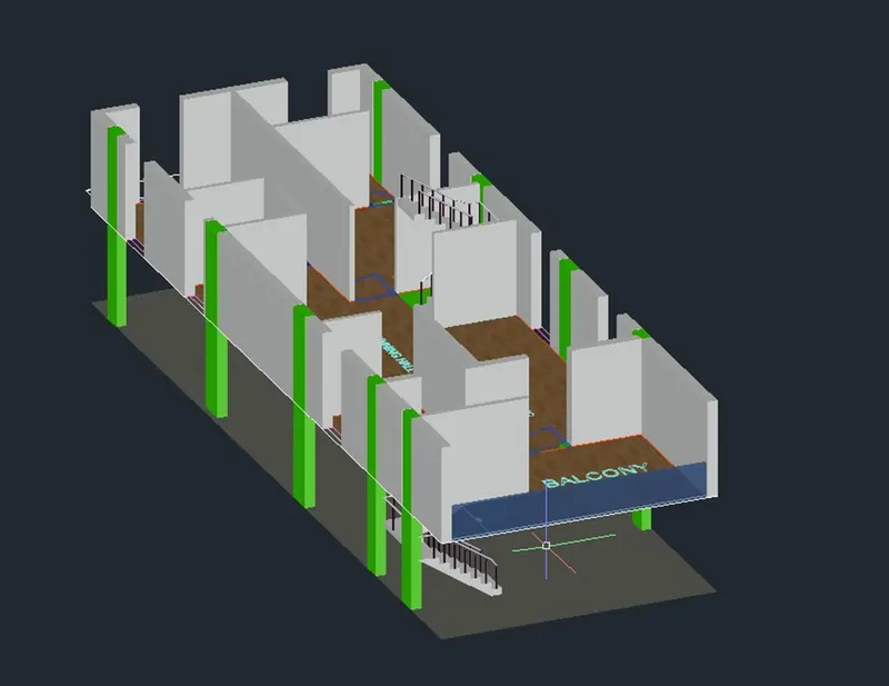
- Applying different material properties to the elements such as Glass, Wood, Floor, Wall paint Etc.
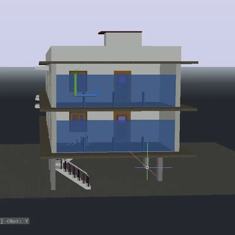
- Here iam using Glass in the first and Second Floor elevations.
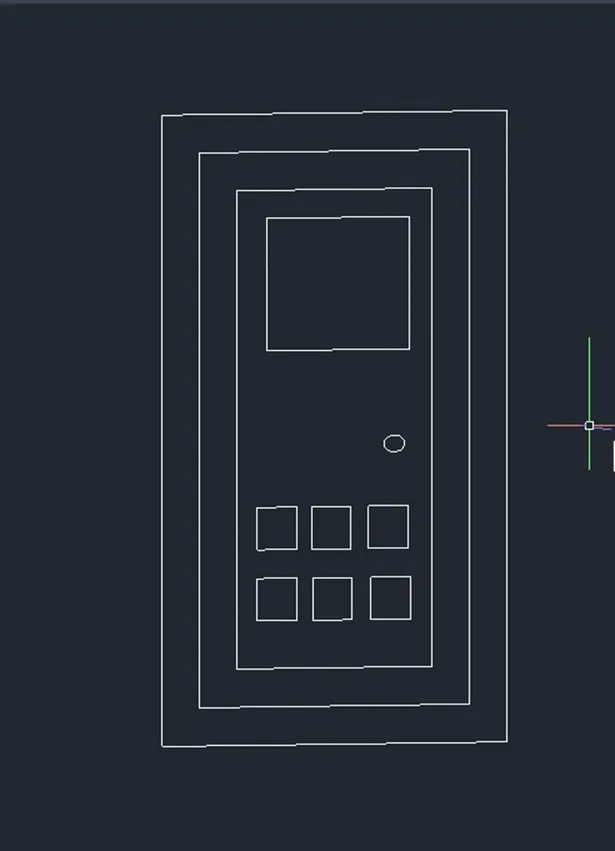
- Using Rectangle, Copy and Offset commands for creating the doors in 2D wireframe.
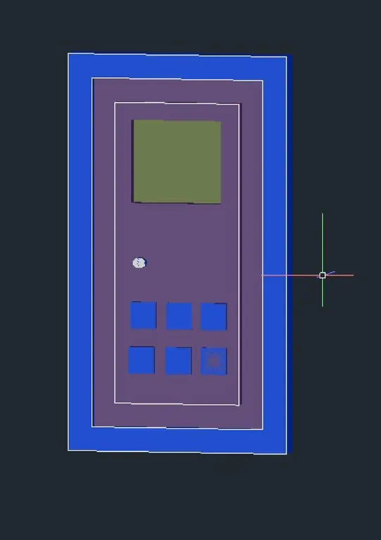
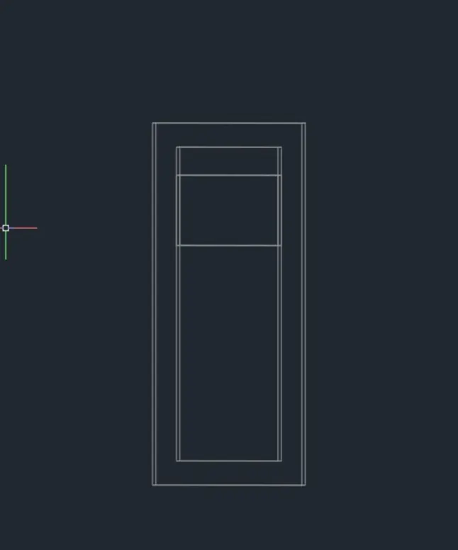
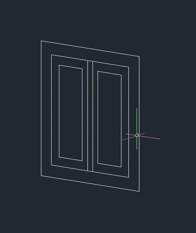
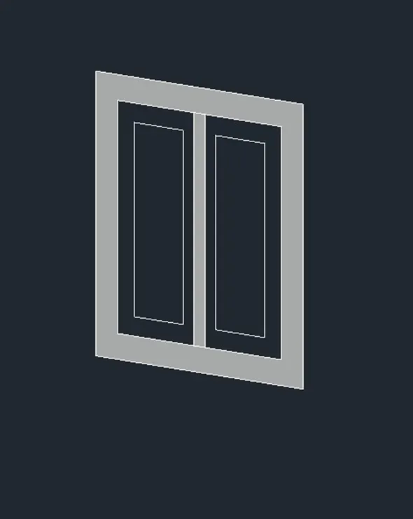
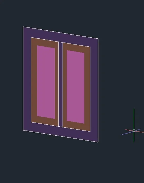
- Then apply the layer to identify the panels frames and elevation.
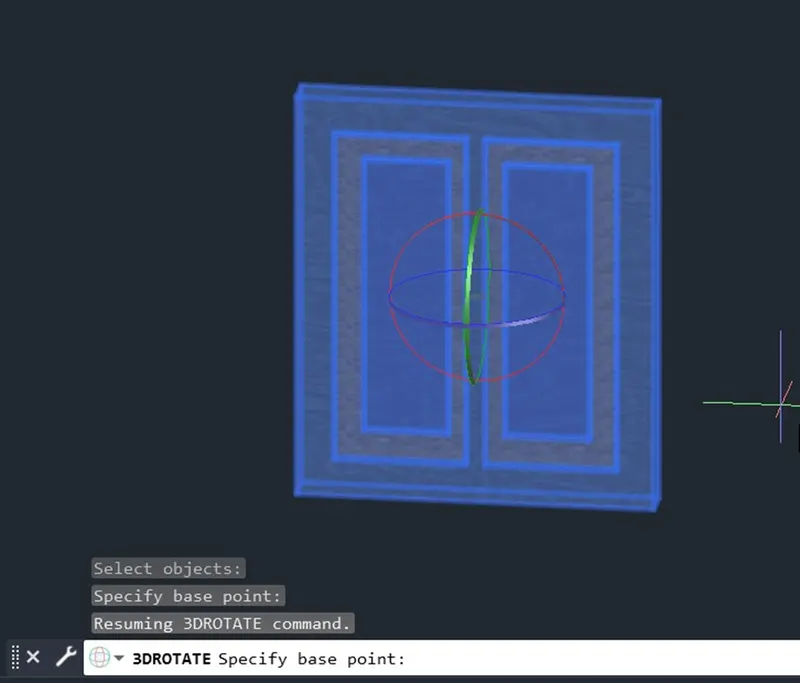
- Using 3DRotate to rotate at required positions.
- Using Subtract, Union and Press Pull command for creating the door and windows.
- Assign the material properties to the elements.
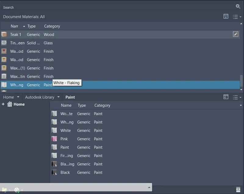
Door1
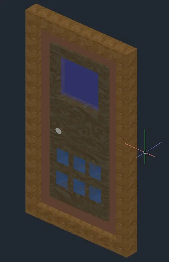
Door 2
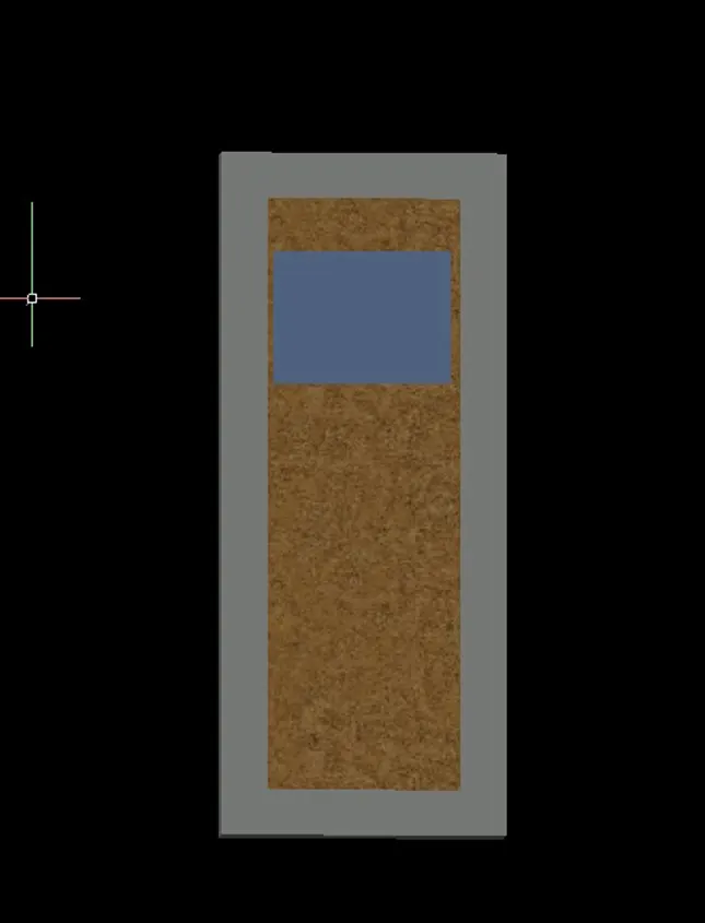
Window
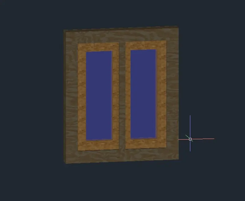
RESULT:
- After Creating Copy them into the required openings.
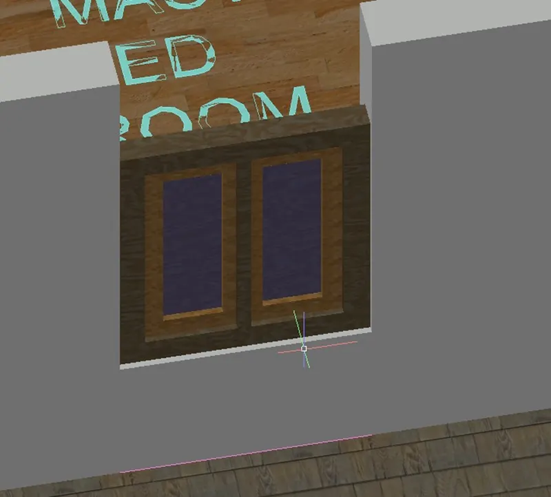
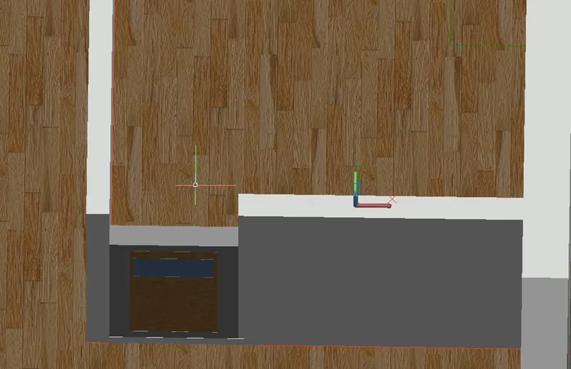
- Using the rectangle or solid box command for fill the remaining portions of the openings.
- Using 3Drotate command to rotate one face to another face.
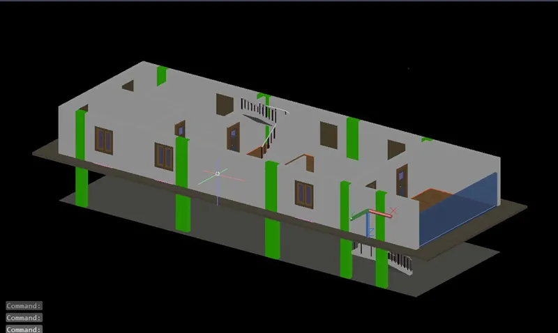
- Assign the material properties to the elements in visuvalization tab material tab browser.
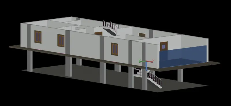
- Placed the all Doors and Windows in the first floor.
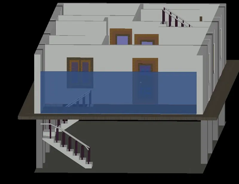
- Creating many view ports for quick edit and work on the specific face.
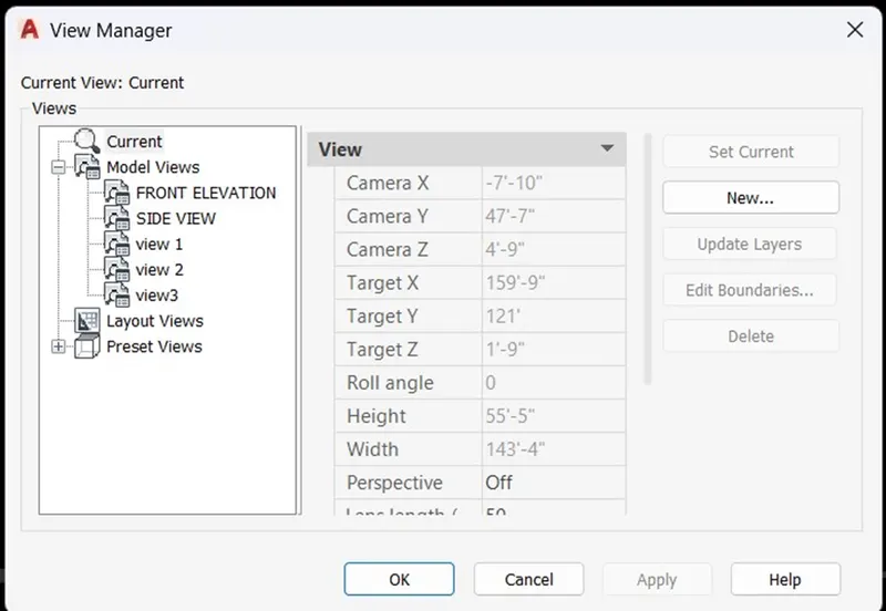
3D view in the wireframe.
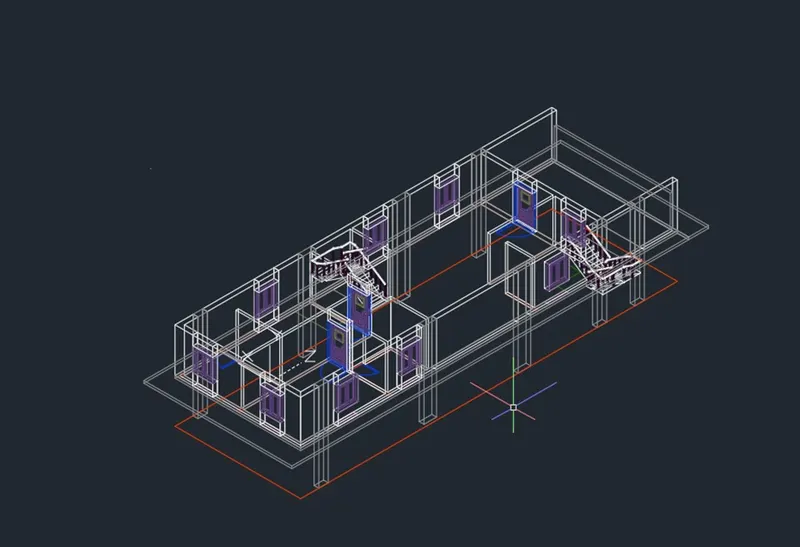
- Create a projection slab and elevation to the building with 6” thickness.
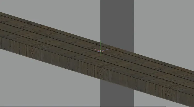
- Copy the First floor portion to make Second floor and make some changes.
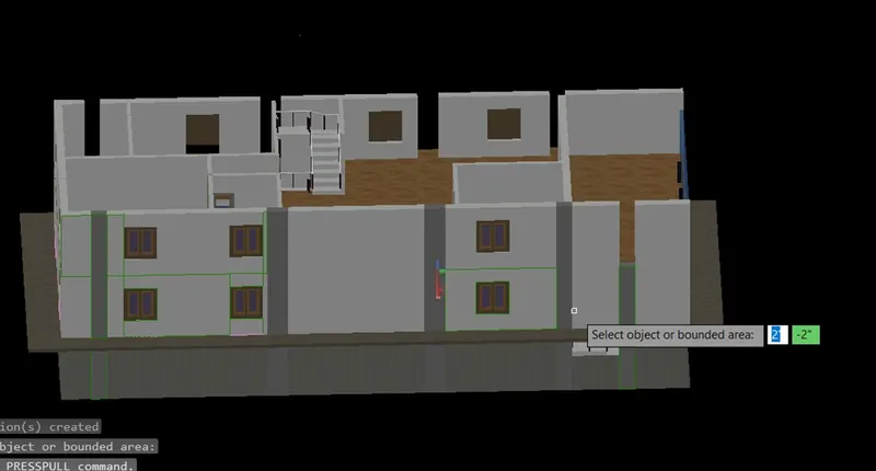
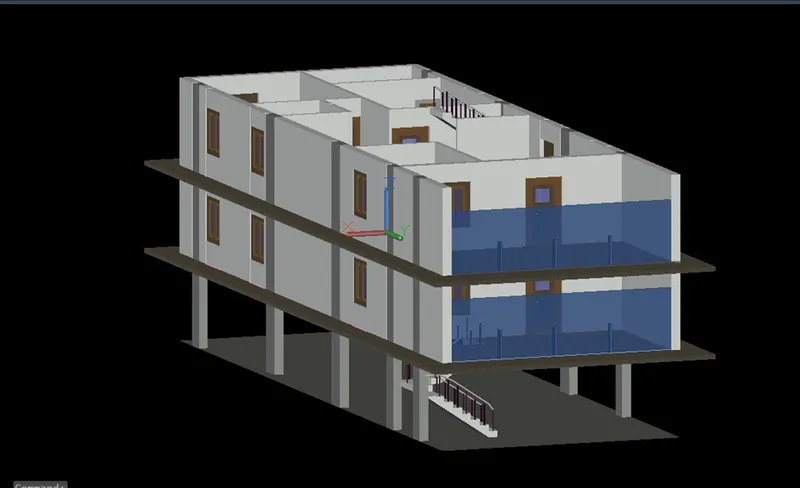
- First and Second floor layouts are same so I copy the exact first floor as second floor.
- Add the floor and copy the projection slab at required position.
- Creating a sunshade or chajja by using Rectangle and Extrude with Tamper on the top of the window.
- Copy the sunshade at the top of all windows and using a 3DRotate to rotate at required positions.
- Using 3Dmirror for mirror the solid object.
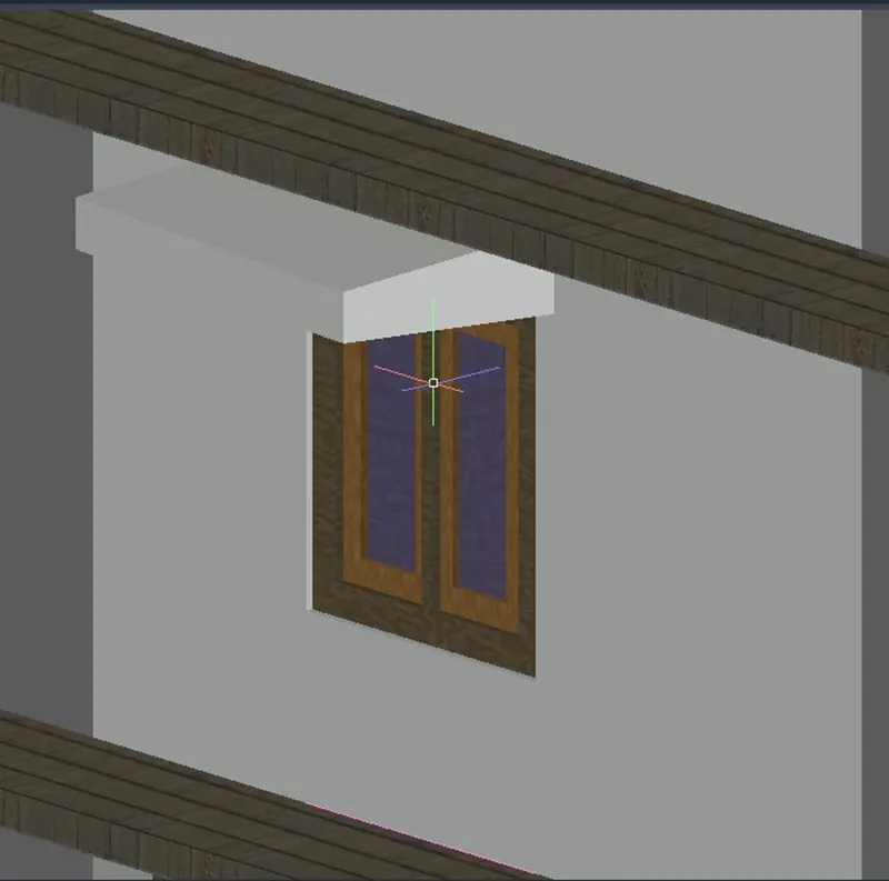
This is the Terrace floor layout.
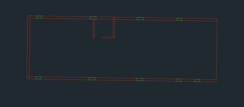
- Create the walls and roof as mentioned above.
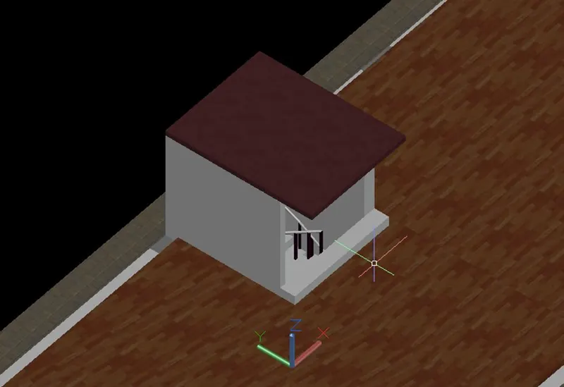
- Create the Staircase head room and the roof and slab of the head room.
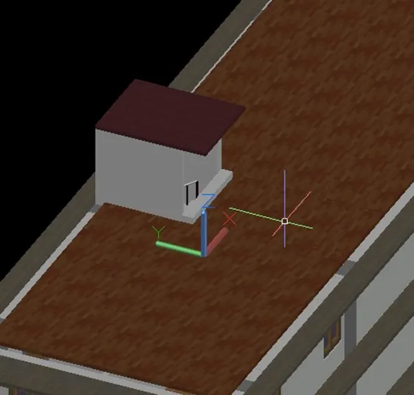
- Assign the material properties to the elements.
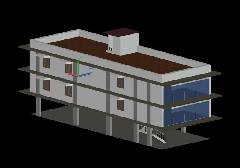
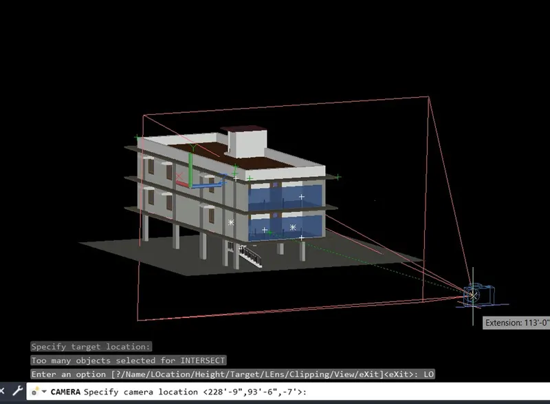
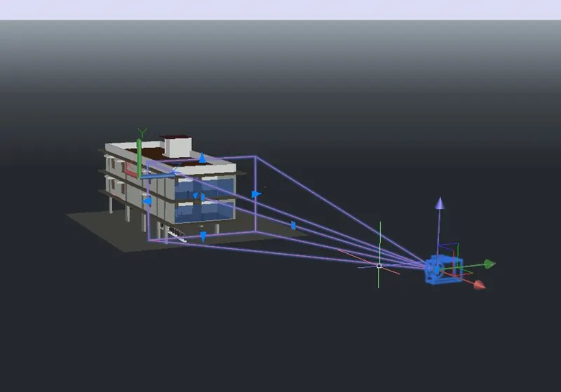
- Set the CAMERA in the visualization tab.
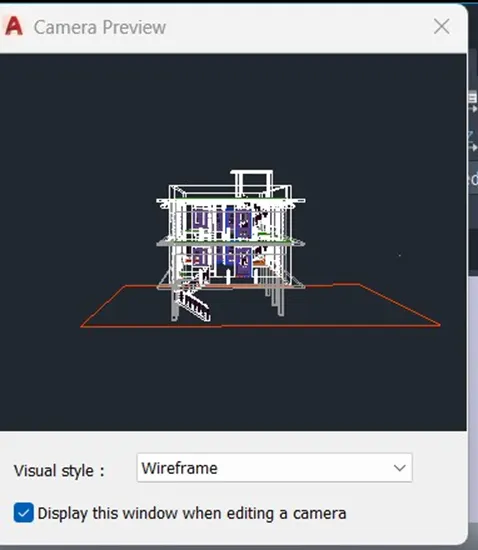
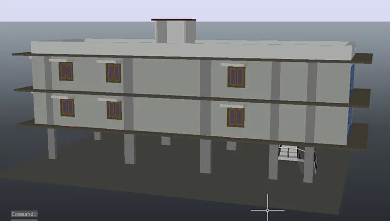
- Preview of the camera view.
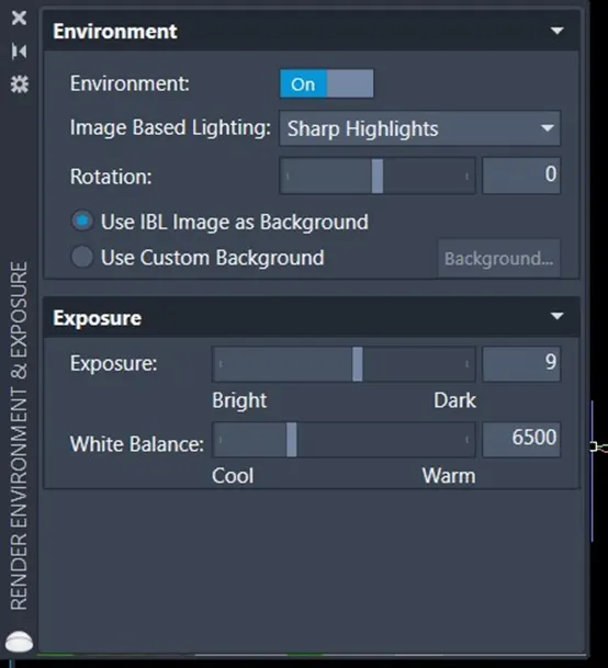
- Change the atmospheric Weather condition in the visualization tab.
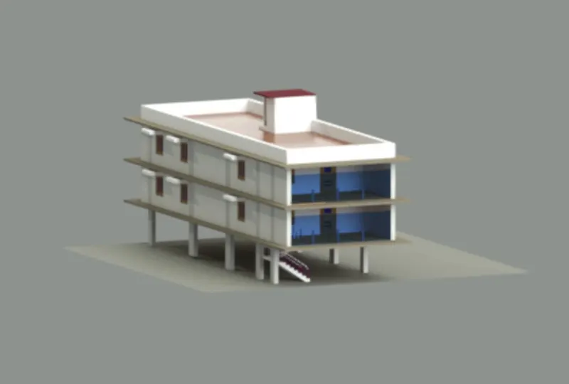
- After completing the creation of residential building here is the final rendered view.
- To create advance rendered go to the visualization tab then Render tab in the ribbon.
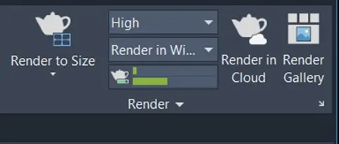
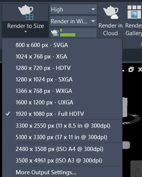
- We can select the quality of the rendered file.
RESULT: