Challenge 2
Aim:-
Que (1):- What are the structural components of a bridge? Explain in detail about the foundation, sub structure and super structure components of the bridge
Answer:-
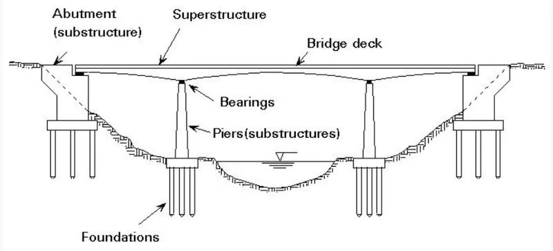
Structural components of bride are categorized into three-part
- Superstructure
The superstructure components of the bridge refer to the components that lie above bearings. which include
- Deck
- RCC Deck Slab
- PSC Deck Slab
- Composite Deck Slab
- Steel Deck Slab
- Parapet wall
- Cast in situ
- RCC parapet
- Handrailing
- Steel
- RCC
- Girders
- I section Grider
- RCC girder
- PSC Girder
- Box Girder
- U Girder
- Steel Plate Girder
- Truss Girder
- Utility
- Cable wire
- Electric poles
- Drainage
- Rail Plinth
- Expnsion Joint
- Sub-Structure
The substructure of a bridge is the component that supports the superstructure and distributes the load to the bridge footings and foundation.
- Bearing
- Elastomeric bearing
- POT- CUM bearing
- Bearing Pedestals
- Seismic arrestors
- Pier Cap
- Prestress pier cap
- RCC pier cap
- Pier
- Circular Pier
- Square pier
- Abutment
- Wing Wall
- Pile Cap
- Foundation
Bridge foundation is the base of a bridge that transmits the loads from the piers, abutments, and wings to the supporting strata.
- Open Foundation
- Pile Foundation
- Well Foundation
Que (2):- What is Super Imposed Dead Load means? What are loads that needs to be considered as SIDL for a metro viaduct bridge?
Answer:-
Other permanent objects such as parapets and road pavement, as well as other non-structural and architectural attachments to the bridge, are called superimposed dead loads. These things are long-term, though they may be replaced during the Structure's lifetime.
It is determined as the product of volume and material density, just like self-weight.
Superimpose dead load include all the weight of materials on the structure that are not structural element but are perment. Follwing are the load include
- Weight of Track
- Plinth
- Rails
- Fasteners
- Cables
- Parapet
- Hand Rail
- OHE mast
- Cable trought
- Signaling equipment
All this will be considered in the design as per the site conditions.
The SIDL can be of two type: Fixed or non-variable, and variable. In case the metro certifies that a portion of SIDL is of fixed or non-variable type and is not likely to vary significantly during the life of the structure and a special clause for ensuring the same is incorporated in the metro maintenance manual, the load factor applicable for dead load may be consider for this component of SIDL
Que (3):- What are the different types of girders that can be used for a metro viaduct?
Answer:-
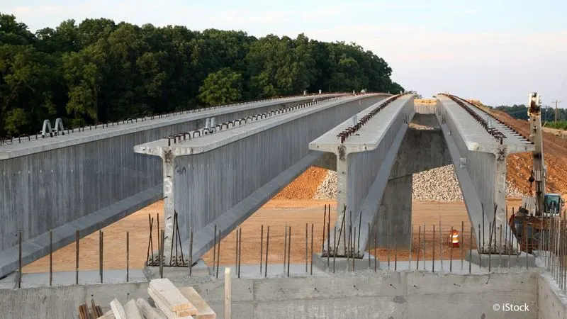
The bridge in which girders are used for supporting its deck is called the girder bridge.
- I / T Girder
A horizontal main structural member as in a bridge that supports vertical loads and that consists of a single piece or of more than one piece bound together.
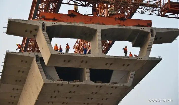
- Box Girder
A box or tubular girder is a girder that forms an enclosed tube with multiple walls, as opposed to an I- or H-beam. Originally constructed of riveted wrought iron, they are now made of rolled or welded steel, aluminium extrusions or prestressed concrete.
For the long it is mostly prefered for long span bridge and it is best for torsion load
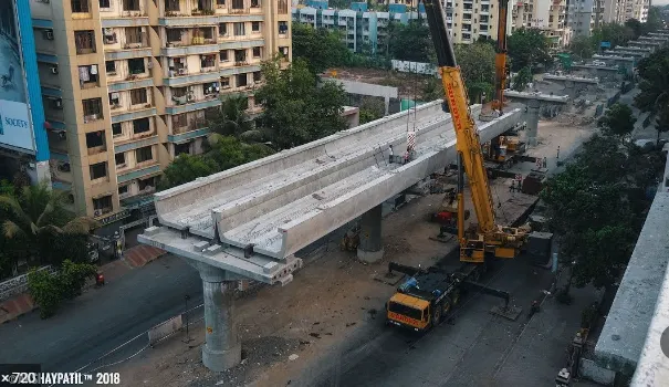
- U Girder
U girders will involve casting the entire span of a viaduct between two piers in a single piece, u grider have many advantage like noise cancelation, fast to construct
It have range between 25 to 28 meter, upto to 27 Meter it is most suitable
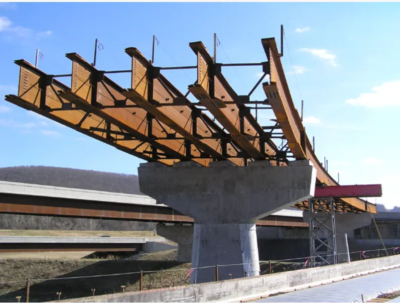
- Steel Plate Girder
Girder bridges are the simplest bridge type in structure and consist of steel beams shaped to an I-section or box section, called a plate girder bridge or a box girder bridge, respectively. Girder bridges are comprised of deck slabs, on which vehicles and people pass, and of main girders supporting the deck slabs.
Que (4):- What are bearings in a metro viaduct? Explain the types of bearings and analyses the types with respect to their advantages and disadvantages
Answer:-
Bridge bearings are structural equipment or devices installed between bridge substructure and superstructure to transfer the applied load including earthquake loads; wind loads; traffic loads; and superstructure self-weight. Bridge bearings also makes rooms for relative movements between superstructure and substructure, for instance, rotation movements and translational movements in horizontal and transverse direction. Bearing used in the construction of bridge structure is divided into two major categories namely expansion bearings and fixed bearings. The former permits both translational and rotational movements whereas the latter allow rotational and limited translational movements.
Followingare the type of bearings
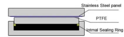
- Sliding bearings
Sliding bearing consist of two metal plates, commonly stainless-steel plates, that slide relative to each other and hence makes room for translational movement and lubricating material between themA friction force is generated in sliding bearing and it is imposed on substructure, superstructure and sliding bearing itself. So, it may be required to provide lubricant such as polytetrafluoroethylene (PTFE) to decline generated friction. It is specified by ASSHTO that sliding bearing cannot be used unless the bridge span is smaller than 15m. This is because sliding bearing cannot be purely used if the bridge experiences rotation movement. However, the span restriction for sliding bearing utilization can be disregarded when it is used in combination with other bearing types.
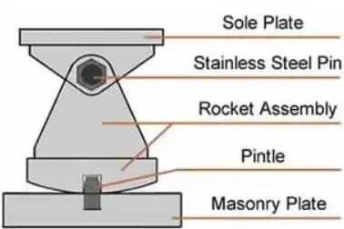
- Rocker and pin bearings
Rocker is an expansion bearing composed of curved surface at the bottom, which accommodate translational movement and a pin at the top makes room for rotation movement Pin bearing is a fixed bearing that make room for rotation movement through the application of steel pin. It has similar structure and component like rocker bearing apart from the bottom of pin bearing which is flat and fixed to the concrete pier Both rocker and pin bearings are mainly employed in steel bridge structure. Rocker and pin bearing should be considered when the bridge movement is adequately known and described, since such bearings can make rooms for both translational and rotational movements in one direction only. These bearings are likely to suffer deterioration and corrosion, so it is necessary to conduct regular inspection and maintenance.
- Roller bearings
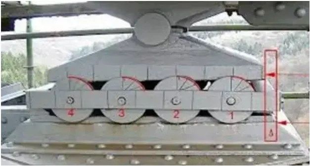
Roller bearing can be used in the construction of reinforced concrete and steel bridge structure. There are two main configurations including single roller bearing which is composed of one roller placed between two plates and multiple roller bearing that consist of several rollers installed between two plates. The former as shown in Figure-5 can accommodate both rotation and translation movement in longitudinal direction and it is cheap to manufacture but its vertical load capacity is limited. In contrary, the latter as shown in Figure-6 can make room for translation movement only and rotation movement can be accommodated if rollers are combined with pin bearing. Multiple roller bearings are expensive and support considerably large vertical loads. Regular inspection and rehabilitation should be conducted since roller bearing are susceptible to corrosion and damages.
- Elastomeric bearings
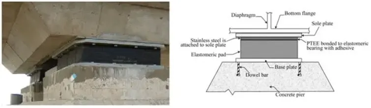
It consists of elastomer manufactured from synthetic or natural rubber and can take both translation and rotation movements through elastomer deformation. The ability of elastomer to carry large vertical loads is because of reinforcement provision that prevents lateral bulging of elastomer. There are number of elastomeric bearing pads classified based on types of reinforcements used. For example, steel reinforced, plain, fiberglass reinforced and cotton duck reinforced elastomeric bearing pads. Strength and response of each type is different, steel reinforced elastomeric bearing is the strongest one and plain elastomeric pad is the weakest. Elastomeric bearing is neither expensive nor requires considerable maintenance, that is why it the most desired bearing type.
- Curved bearings
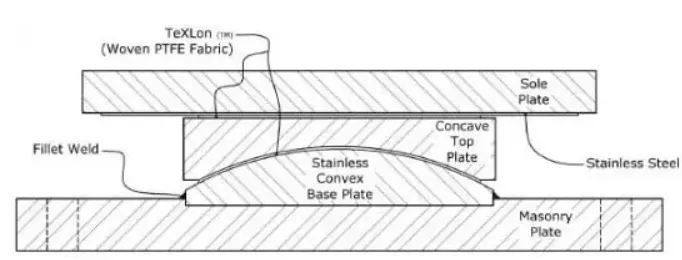
It consists of two curved plate that match each other as shown in Figure 8. If curved bearing is cylindrical, then it only accommodates rotation movements. However, both rotation and translational movements can be dealt with if curved bearing is spherical. Due to the fact that both gravity loads and curved geometry generate lateral resistance against and consequently lateral movement would be limited, that is why polytetrafluoroethylene (PTFE) slider is adhered to the bearings in order to make rooms for lateral movements.
- Pot bearings
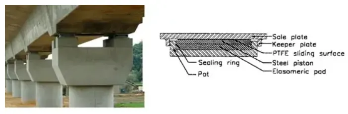
Bearing consists of elastomeric disk confined in a pot, steel piston that is properly tailored into the pot wall and flat sealing rings which keeps elastomeric inside the pot. Pot bearing can support considerable vertical loads and it is commonly transferred through steel piston to the elastomeric disc which is almost incompressible. As far as lateral load is concerned, it is transferred as the steel pistol moves toward pot wall. Translational movement is limited in pure pot bearing that is why PTFE are introduced to the sliding surface to make rooms for translation movement.
- Disk bearings
Different components of disk bearing are shown in Figure-10 in detail. Rotation movement is accommodated through the deformation of elastomer whereas the translation movement is considered through the application of PTFE slider. The utilized elastomer should be adequately hard to support vertical loads without suffering large deformations and sufficiently flexible to allow rotational movement. Both vertical loads and lateral loads are supported by elastomeric disk and metal ring in the center of the bearing respectively.
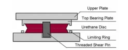
Que (5):- During the construction of metro viaducts across water passages, explain the topographical check list that needs to be considered for the designing the height of the viaducts?
Answer:-
For construction of a metro viaduct across water passage, we need to collect hydraulic design data,
Checklists shall be done before designing the metro viaduct
- Determination of Design Highest Flood Leve
- Determination of Design Discharge
- Discharge for Design of Foundation and Protection Works
- Determination of Waterway
- Linear waterway
-Restricted Waterway
-Effective Linear Waterway
- Determination of Afflux
- Freeboard
- Vertical Clearance over HFL
- Determination of the Maximum Depth of Scour
- River Training and Protection Works
- Hydraulic and Mathematical Model Studies
Que (6) What are the different types of girders that can be used in a metro viaduct construction? Explain the differences of the girders and elucidate how a designer has to choose his girder type whilst designing.
Answer:-
- I / T Girder
Generally I Girder is for Use all type of structures it is a universal girder for the long-range and short range this girder is used, It is consist of two type RCC & PSC property, Form the designer point of view we can manage the lenght of girder in longitudinal direction, economy wise it is also good
I gired is most comenly use girder in construction, Any contractor has a tendency to cast this type of girder
- Box Girder
Box girder is also known as segmental girder, Nowadays it is preferred in the construction field because for the long span up to 35 meter it is suitable, It has a high torsion load capacity for the heavy construction it may be prefered, we have to connect all segments one by one to complete the one girder, It is time taking process
- U Girder
U girder is most use in metro project because u girder have many benefits rather than other girders it has a longitudinal range between 25 to 28 meter, 27-meter longitudinal span most prefered,
From the design point of view it is best for the short range of girder, completely one whole segment is cast in the workshop because of that speedy work has done on the site
- Steel Plate girder
For the long sapn bride and curving span this girder is used it made up of full steel
Que (7) Explain why the choice of metro designers would be precast U girders in India.
Answer:-
U Girder is most popular choice supersrtucture by the metro designer in the elevated metro project, It has beter quality and it is open structure easy to construct also it is slender section lite weight In u girder rail is runing at lower location economy wise cost also saved and two sides of this girder act as a parapet wall so additional parapet cost is an increase structural element of u girder is good aand asol act as a noise barried in citys, they are easy to construct & errect time taken for construction is 2 to 3 hour as compair to other girder speed of construction is very fast, we can cast the whole girder at workshop and bring to site and place it on pier cap at less time and without disturbing traffic also, It is the very thin section it has less dead weight as compair to other girders, so less dead weight means we can also reduce the weght of other component, The range of u girder is upto 30 meter and probal rang for design and construction is betwwen 25 to 27 meter because in that range it have capacity to resist the torsion load coming on girder, that all the reason why designre choose for U girder
Que (8):- What is an open web structure? Brief the advantages of the system.
Answer:-
Open web structure is most poperly use structure nowadays, open web structure is called because the web is not connected to each other the upper part of the structure is open It is quitl efficient structure to construct because it is light weight &b easily lifted from the ground & put it on pier cap & another advantage are it is a precast element it is made in casting yard with good quality controls concrete is effectively utilize and we get cost efficient structure the girder can be easily lifted by crane and bearing can be placed this can be done in less time those all are the advantage of open web structure
Que (9):- Explain the load flow behavior in a open web girder.
Answer:-
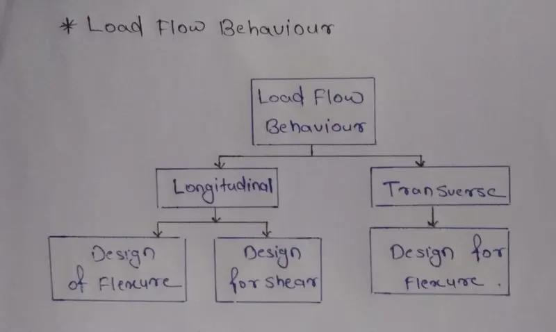
Train is moving on the girder and wheel causing longitudinal bending and transverse bending so that we have to design the girder in longitudinal direction as well as in transverse direction, For the designing of girder we have to make to separate model in software one is for longitudinal model and another is for the transverse model. In the longitudinal direction prestressing takes all the load on structure and in transverse direction reinforcement takes all the load of the structure
Que (10):- As per IRS CBC, Table 11(Clause 10.2.2) the stress limitations of SLS, Explain your understanding of the table and how it correlated while designing a viaduct for metro rail construction.
Answer:-
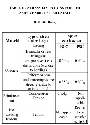
For the material concrete Triangular or near triangular compressive stress distribution (e.g. due to bending) is considered 0.50fck for RCC and 0.40fck PSC because the fiber in this regin is faraway that why this data is consider for other stress loading Uniform or near uniform compressive stress (e.g. due to axial loading) is consider 0.38fck and for PSC 0.30fck because fiber is closure
For reinforcement compressin tension 0.75fy is considered from background data this all data are given in IRS CBC code.
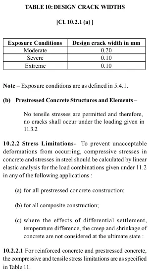
Que (11):- Explain your understanding of crack widths. Brief the three different design crack widths with respect to IRS CBC
Answer:-
The crack width of a flexural member is obtained by multiplying the maximum crack spacing by the mean strain of the flexural steel reinforcement. Therefore, the crack width depends on the nature and the arrangement of the reinforcing steel crossing the cracks and the bond between the steel bars found in the tension zone of concrete.