Project 1
Project 1 :-
To Create a Station model of Metro rail project which is located at Ahmedabad city and applying the dead load , IRS live loads , Earth pressure load , wind load and seismic loads to the structure and perform analysis using STAAD.Pro software.
Given Data :-
- The unit weight of soil as 18 kN/m3.
- Use IS 875 part 3 code book for finding the Basic wind speed.
- Use IS 1893 code book for determining the seismic zone.
Calculating Mannual Loading of all the Load
1) DEAD LOAD
- For calculating dead load we have to assume all the size of structure.
- Assumption of all the structure size are given in below image.
- Lenght of the model we assume 20 Meter.
- Width is 24 Meter.
- And unit weight of the RCC structure is 25 kN/`m^3`
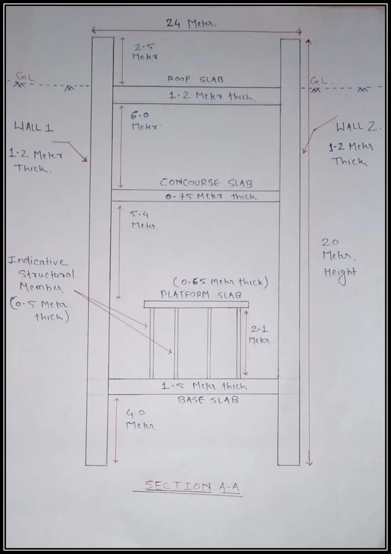
A) Dead load calculation for wall 1 and wall 2.
Calculation for first wall.
Volume X unite wt.
= 20 x 20 X 1.2 X 25
=12000 kN/`m^3`
We have two wall so multiplying load with 2
= 12000 X 2
= 24000 kN/`m^3`
:. Dead load on Wall 1 and Wall 2 is 24000 kN/`m^3`
B) Dead Load Calculation for Roof slab.
- With of the slab is 21.6 ( 24 - 2.4 = 21.6)
= 20 X 21.6 X 1.2 X 25
= 12960 kN/`m^3`
:. Dead Load On roof slab is 12960 kN/`m^3`.
C) Dead load calculation for concourse slab
= 20 X 21.6 X 0.75 X 25
= 8100 kN/`m^3`
:. Dead load on slab is 8100 kN/`m^3`
D) Dead load calculation for Base slab.
= 20 X 21.6 X 1.5 X 25
= 16200 kN/`m^3`
:. Dead Load on base slab is 16200 kN/`m^3`
E) Dead load calculation for platform
- Width of platform is platform is 13.50 meter.
= 20 X 13.50 X 0.65 X 25
= 4387.5 kN/`m^3`
:. Dead load on platform is 4387.5 kN/`m^3`
F) Dead load calculation for indicative structural member.
= 20 X 2.1 X 0.5 X 25
= 525 kN/`m^3`
We have 4 nos of member so multiply load with four.
= 525 X 4
= 2100 kN/`m^3`
Total load of member is 2100 kN/`m^3`
Now,
We have to calculated total dead of member so we have to add all the which we calculated.
= Wall load + Roof slab + Concourse slab + Base slab + Platform + Indicative member
= 24000 + 12960 + 8100 + 16200 + 4387.5 + 2100
= 67747.5 kN/`m^3`
Total Dead load of structure is 67747.5 kN/`m^3`
2) EARTH PRESSURE LOAD
- Height of the structure below ground level is 17.5 meter
- Unite weight of the soil is given 18 kM/`m^3`.
- Assuming angle `theta` = `25^0`
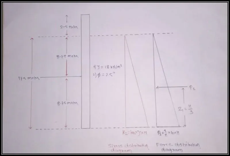
First we need to determin the value of Ka by using rankine method
ka=`(1- sin theta)/(1+sin theta)`
= `(1- sin 25)/(1 + sin 25)`
= 0.406
Now we need to calculate the earth pressure acting on wall (K1)
K1 = Ka X Unit wt of soil (`gamma`) X height of structure (H)
= 0.406 X 18 X 17.5
= 127.89 kN/`m^2`
Value of P1 we need to calculate.
P1 = `1/2` X K1 X H
= `1/2` X 127.89 X 17.5
= 1119.03 kN
P1 act at a distance Z1
Z1 = `H/3`
= `17.5/3`
= 5.83 M
Total Earth presure load acting on Wall is 127.89 kN/`m^2`
3) WIND LOAD
We have to calculate wind speed as per IS 875 part 3 following are data given below
- Basic wind speed of ahmadbad city is 39 m/s
- K1 factor is 1.06
- k2 factor is 0.80
- K3 factor is 1
- k4 aslo 1
First we need to calculate the Design wind speed (Vz)
Vz = Vb X K1 X K2 X K3 X K4
= 39 X 1.06 X 0.80 X 1 X 1
= 33.072 m/s
Wind pressure (Pz)
Pz = 0.6 X `(Vz)^2`
= 0.6 X `(33.072)^2`
= 656.25 N/`m^2`
= 0.65625 kN/`m^2`
Wind pressure acting on structure is 0.65625 kN/`m^2`
4) SEISMIC LOAD
We have to calculated seismic load from IS 1893 (part 1): 2016
- Ahmedbad city is coming under zone III
- Suitable factor we have to consider in staad.pro software.
Creating Model and performing analysis using STAAD.pro software.
Step (1) :- Creating Model in STAAD.pro software.
- First open a staad.pro software.
- Fill all detail regarding model in software.
- Then click on create option to start the software.
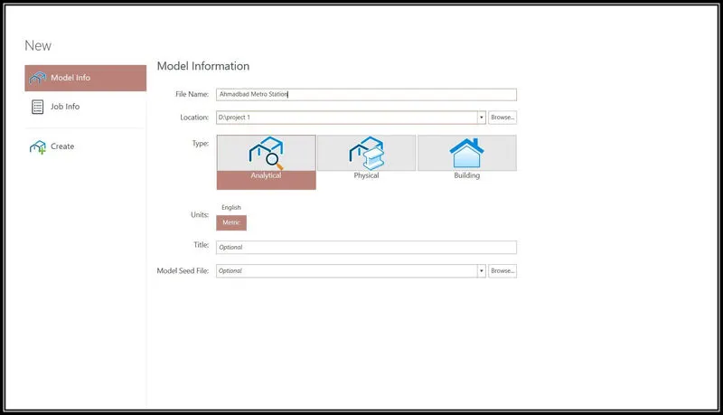
Now we need to create the model
- Create a first node using coordinate
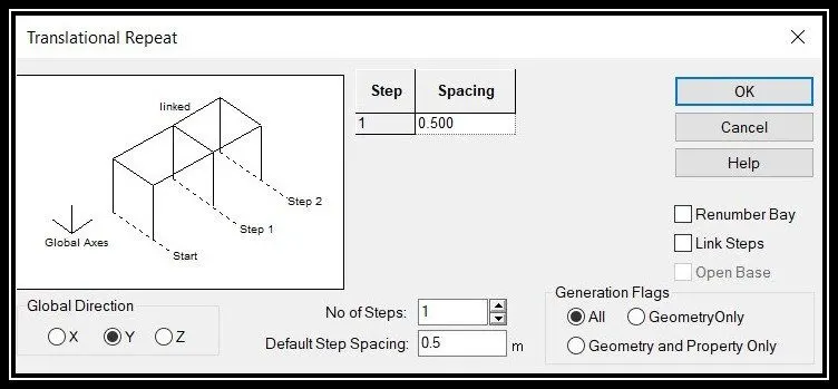
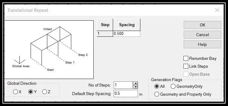
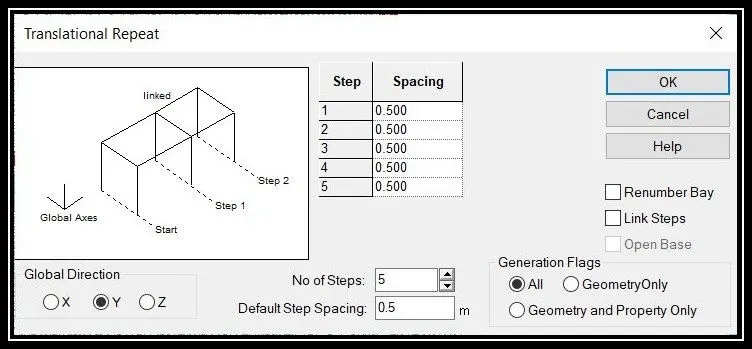
- Select that node using node cursor and copy it in Z direction upto 0.5 meter using translational repeat option.
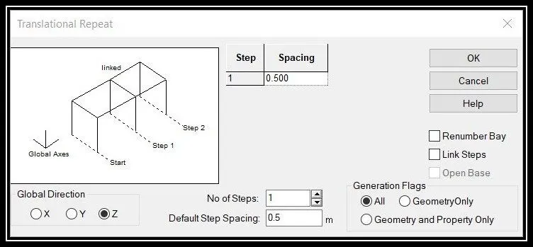
- Again select both the node and copy them in Y direction upto 0.5 meter height using translational repeat option.
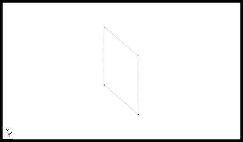
- Now we need to add plate in that created node
- For go to geometry option in that select add plate option by using this option insert the plat in created node.
- Hence one plate is created.
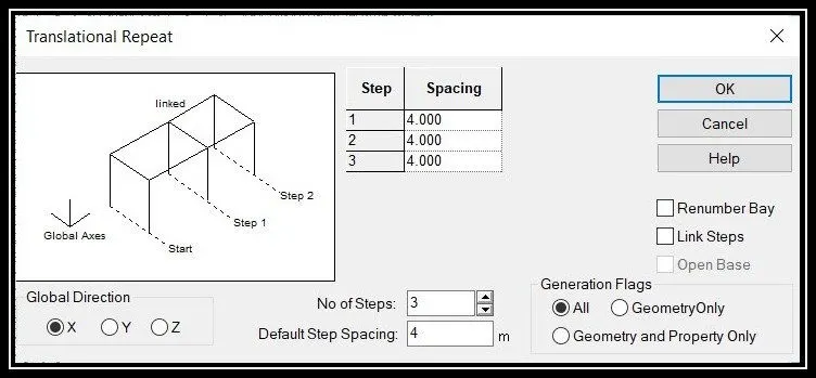
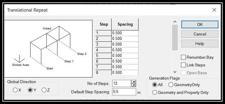
- Select that plate using plate cursor copy it in Y dirction using translational repeat option upto 4 meter height.
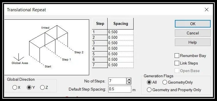
- In translational repeat option no of step is 7 and direction Y and spacing should be 0.5 meter then click on Ok to create.
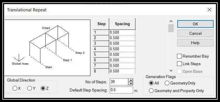
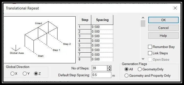
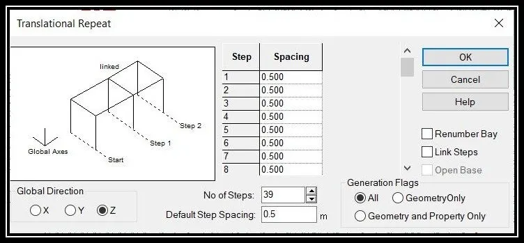
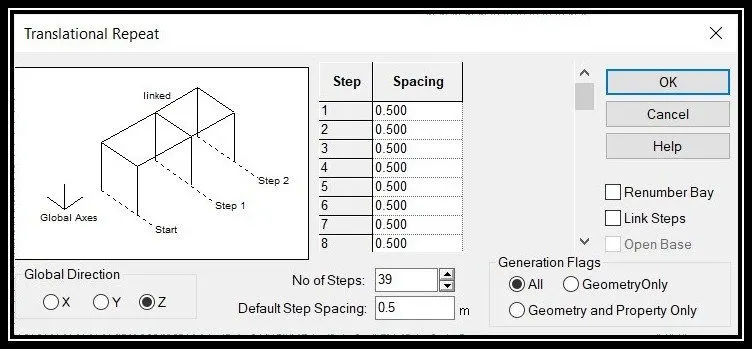
- Again select all the plate and copy them in Z dirction upto 20 meter length.
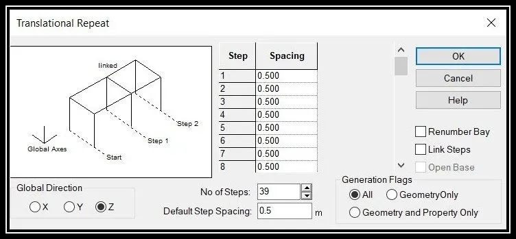
- We assume lenght of the structure is 20 meter, so no of step will be 39 nos and spacing is 0.5 meter.
- Again select all the plate and copy them in X diection upto 22 meter ( Because width of the bridge is 22 meter ).
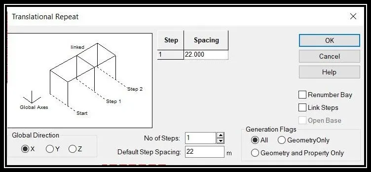
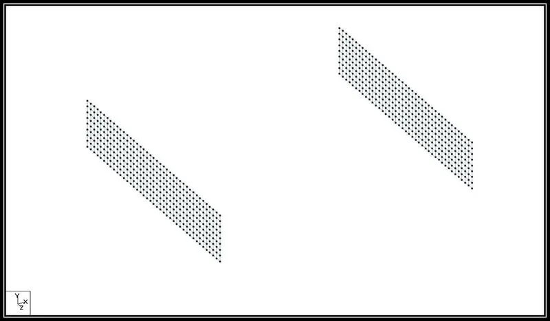
Now we are creating base slab,
- For that select top both the node of the first plate and copy it in X direction upto 0.5 meter.
- Inster the plate in that node using add plate option.
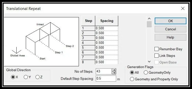
- Then select that plate and copy them in X direction using translational repeat option.
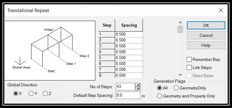
- In translational repeat option no of steps is 43 no (:. 22/0.5=44, 44-1 = 43 nos)
- Direction is X and spacing should be 0.5 meter.
- Againg select all the base plate which we created and copy them in z direction.
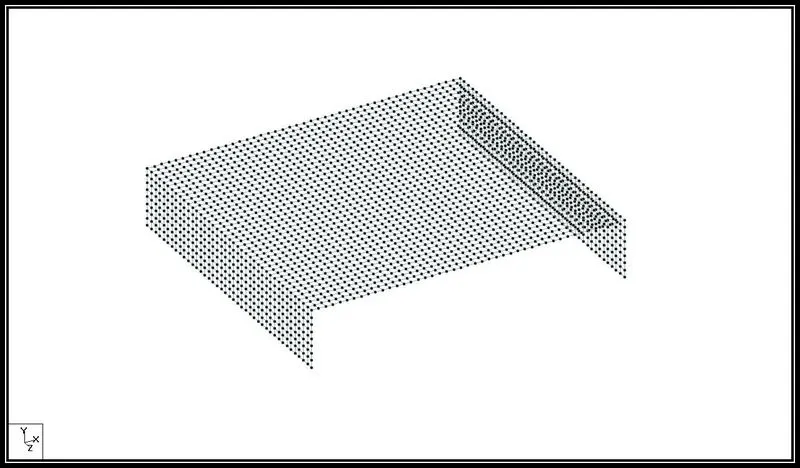
Creating Indicative structural members.
- First select both the node base slab which is loacated 5 meter distance from first node.
- Copy both the node in Y direction upto 0.5 meter using translational repeat option.
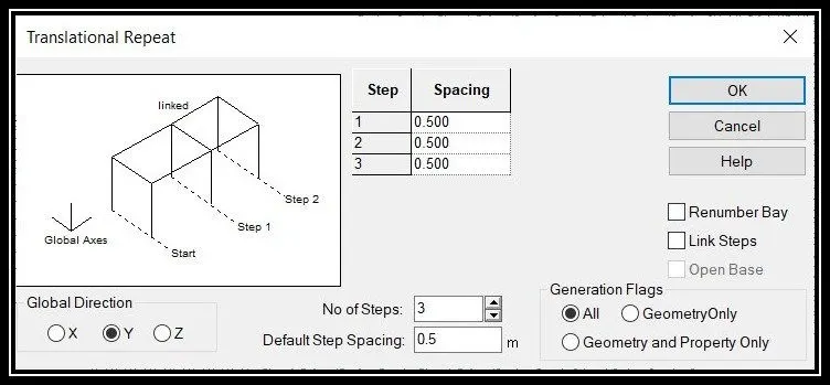
- Now add plate in created node.
- Then select that plate and copy it in Y Direction upto 2 meter height.
- Againg select all the plate and copy them in Z direction upto 20 Meter.
- We have to 4 nos structurel member so select all the plate and copy in X dirction.
- Hence all plate is created.
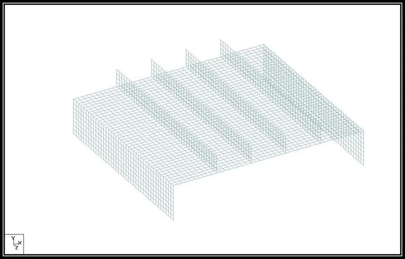
Creating platform slab.
- Select top both node of first plate indicative structural member.
- Then copy them in X direction upto 0.5 meter and add plate in that node.
- Then select that plate and copy them in X direction.
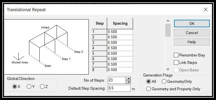
- again select all the plate and copy them in Z direction
- Hence Platform slab is created
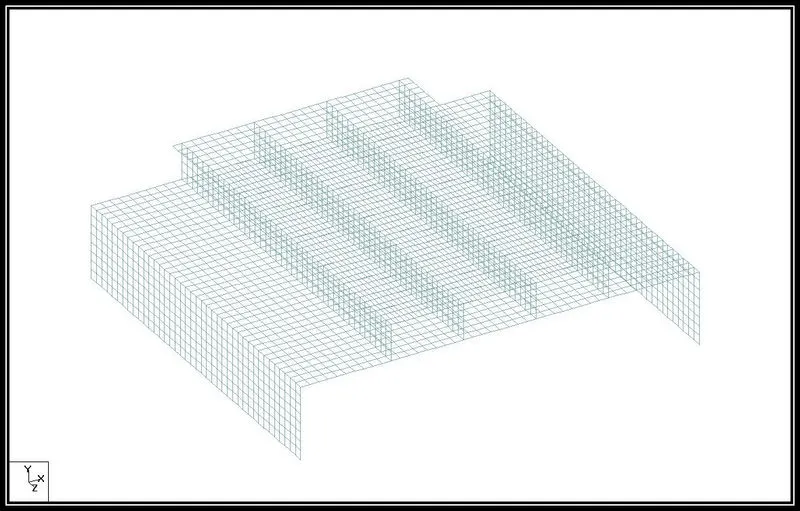
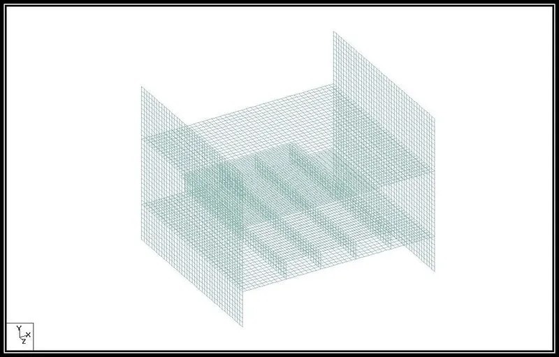
Creating both the wall upto 7.5 meter height
- Select the plate of both the wall which shown in below image.
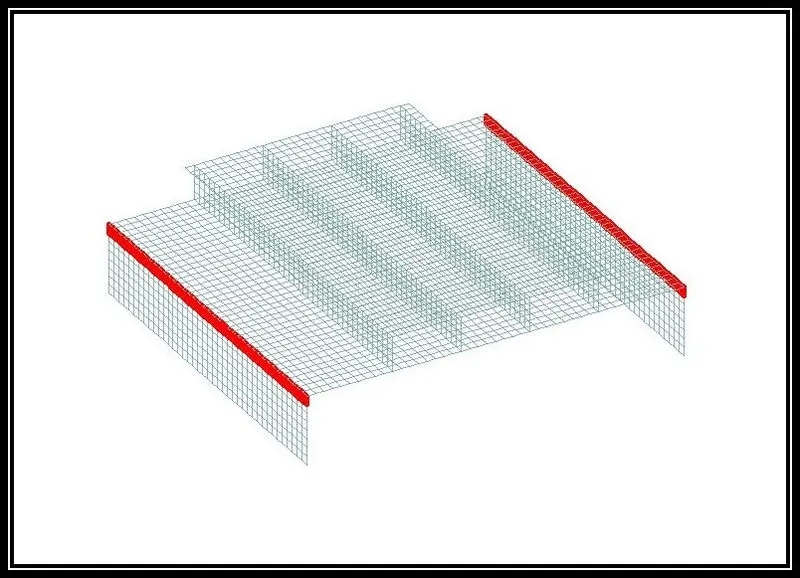
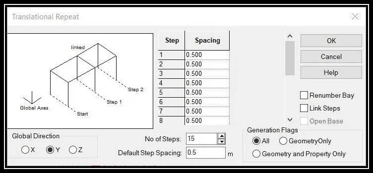
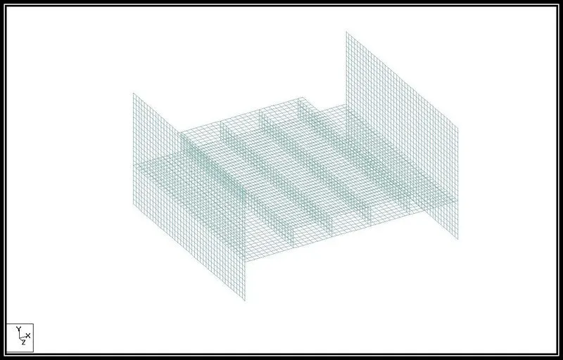
- Copy this selected plate in Y direction upto 7.5 meter using translational repeat option.
Creating Concourse level slab,
- Select top both the node of first plate and copy them in X direction using translational repeat option.
- Then insert plate in that node using add plate option
- After creating plate Select that plate and copy them in X direction using translational repeat option.
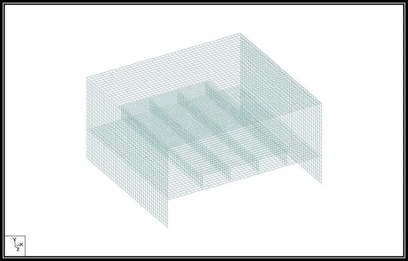
- Again select all the plate and copy them in Z direction upto 20 meter.
- Concourse slab is created
Again creating both wall upto 6 meter height,
- Select bothe wall plate as we select in above step.
- Then copy them in Y direction upto 6 Meter height using translaional repeat option.
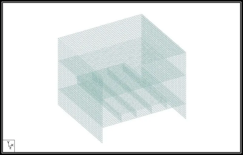
Creating Roof slab
- Select top bothe the node of first plate in copy them in X direction using translational repeat option.
- Then insert plate in that node using add plate option.
- After creating plate Select that plate and copy them in X direction using translational repeat option.
- Again select all the plate and copy them in Z direction upto 20 meter.
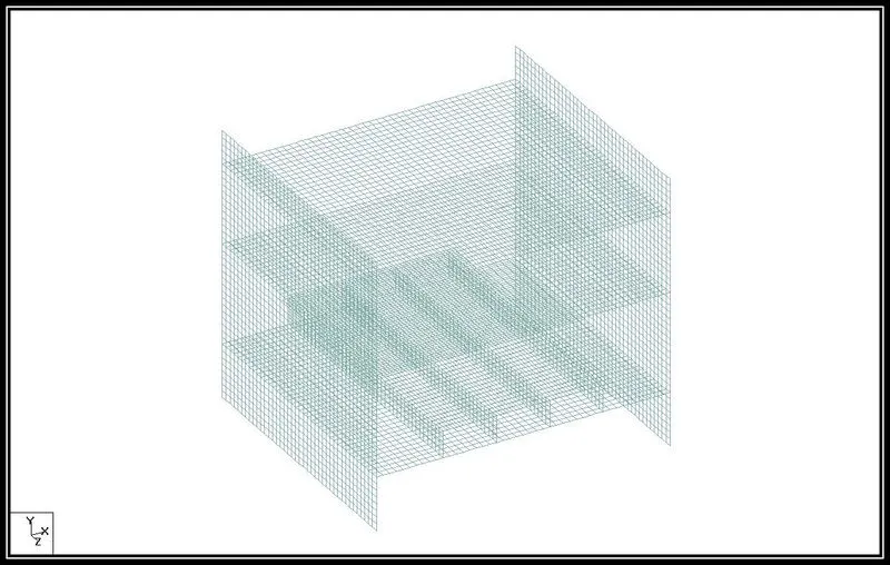
Creating both wall above ground level,
- Select the both wall plate and copy them in Y direction upto 2.5 meter height
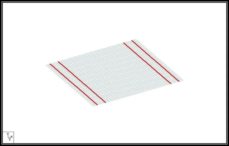
Adding beam to the structure.
- Beam we are creating above the base slabe both side of the platform.
- We are creating beam from distance wall upto 1.5 meter in X direction.
- For adding beam go to specification in that select add beam option.
- Select node from distance 1.5 meter
Creating support to the structure
- For creating support first go to specification in that select fixed support option.
- Then create support option window will open in that window click on add option.
- After that this window will open.
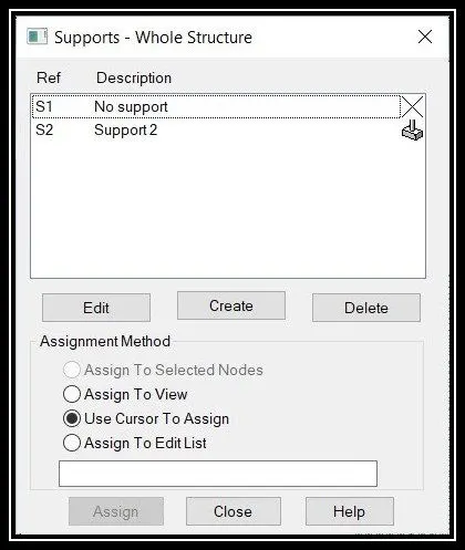
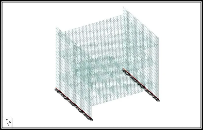
- In above window click on support 2 option then mouse cursor will change by using this cursor select all buttom node of the structure.
- After that select Assign To selected nodes optionin above window.
- Then click on assign button to add the support.
- All support is assign.
Step (2) :- Adding and Assigning property to the structure.
- First we are adding property to the both the wall
- For that go to specification then click on plate thickness then plate property element window will open.
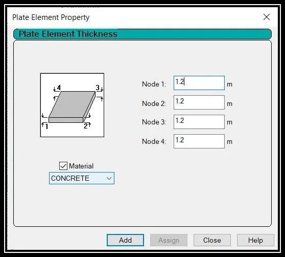
- In plate property element window put the size of plate as 1.2 meter then click on add button.
- After that select both the wall plate of the structure and assign this property to it.
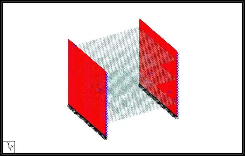
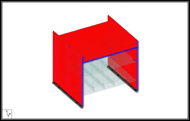
- Adding and assigning 1.2 meter plate thickness to the roof slab.
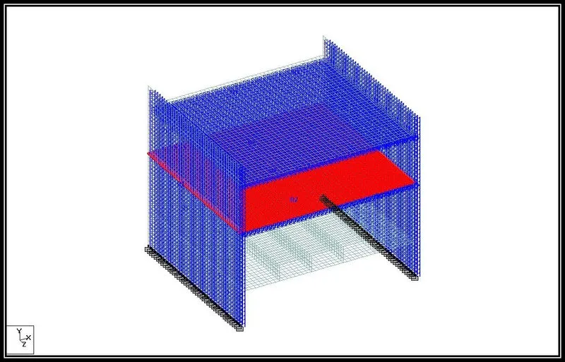
- Adding and assigning 0.75 meter thickness to the concourse slab.
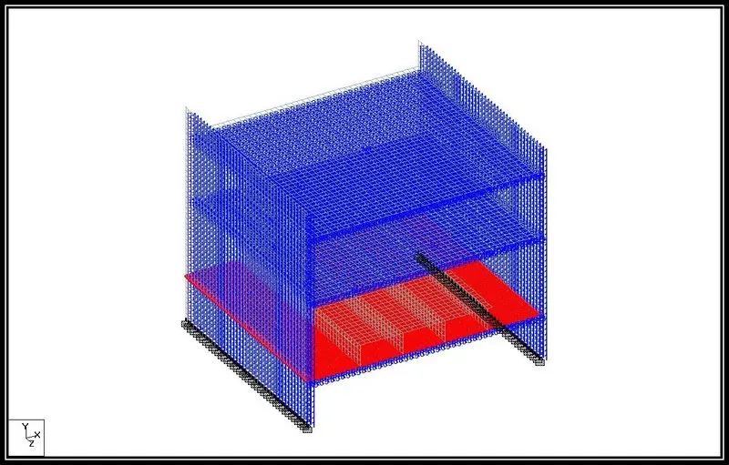
- Adding 1.5 meter plate thickness to the base slabe
- Adding 0.65 plate thickness to the platform slab.
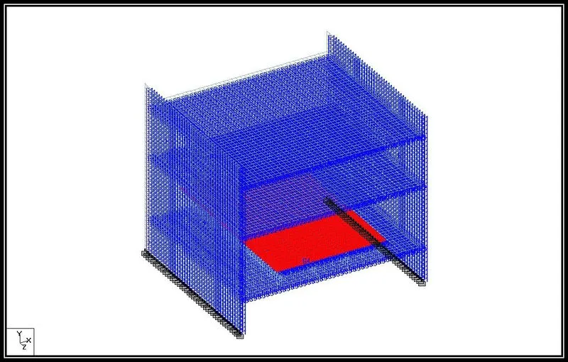
- Adding 0.5 meter plate thickness to the indicative structural member.
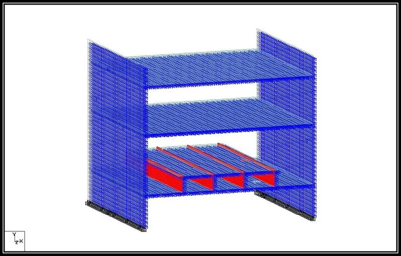
- Now adding size to the beam.
- For that go to specification in that click on prismatic option.
- Then property window will open.
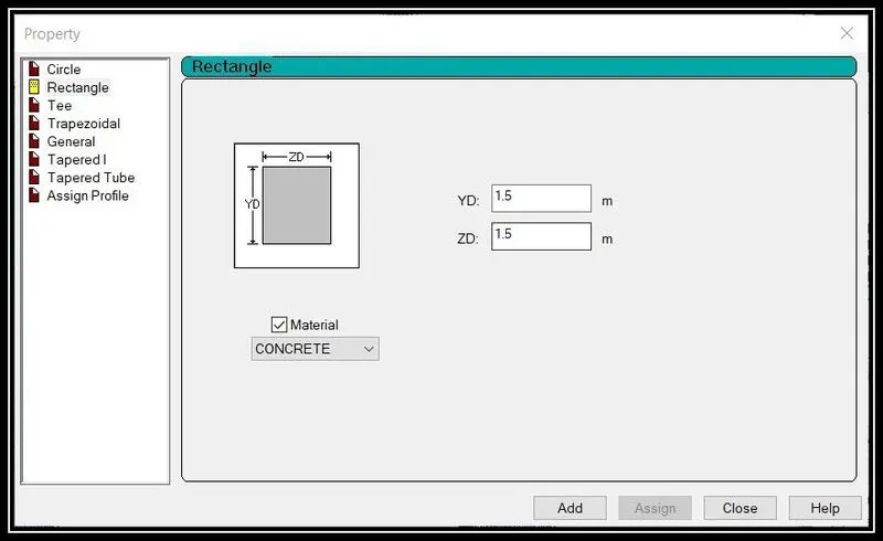
- In above window select rectangle option and add size of beam as 1.5 M X 1.5 M.
- After that select all the beam and assign this property to it.
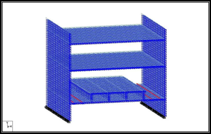
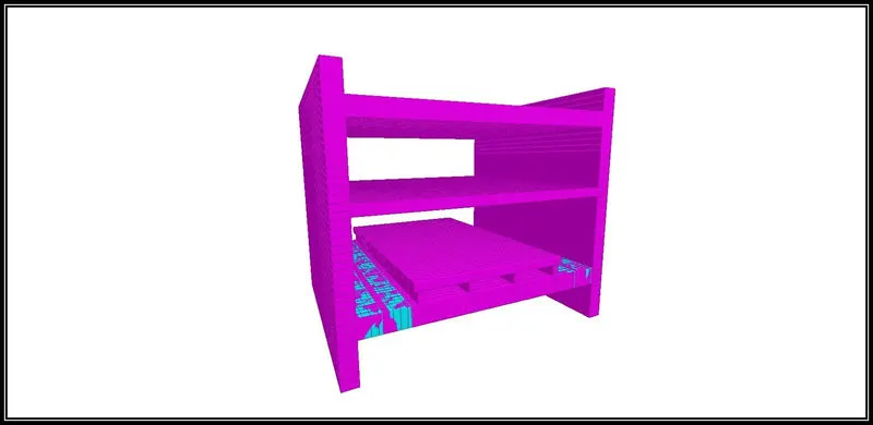
3D Model
Step (3) :- Adding load to the structure.
A) Seismic Load
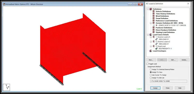
- For adding seismic load go to loading option.
- In right side of the window there is load & defination window is there.
- By using this window define first load case as seismic load.
- Go to defination option.
- Then select seismic defination then this window will open.
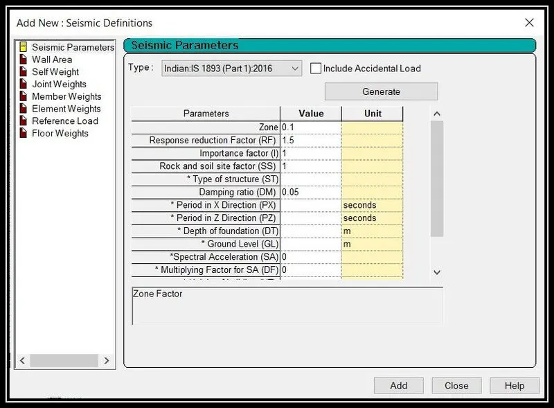
- In above option click on generate option then seismic parameters window will open.
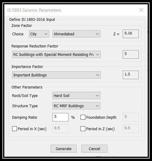
- In that window select city as ahmedabad and responce reduction factor as RC building with special moment resisting frame.
- And importance factor as important building.
- Then click on generate option then click on add.
- Also add selfwt factor in seismic defination.
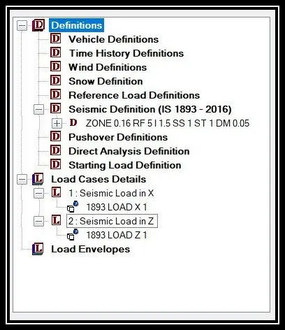
- Now create load case detail for seismic load for that click on load cases detail then click on add then this window will open.
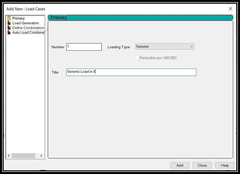
- Create 2 loadcases first is in x direction and second is in Z direction.
- After creating load case select first load case and click on add option the add:item window will open.
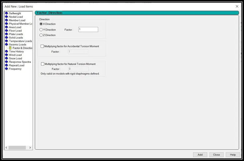
- select direction as X and then click on add option
- Repeat same procedure for second load case
- In second load case select direction as Z.
B) Dead Load
- For creating dead load create one loadcase as dead load
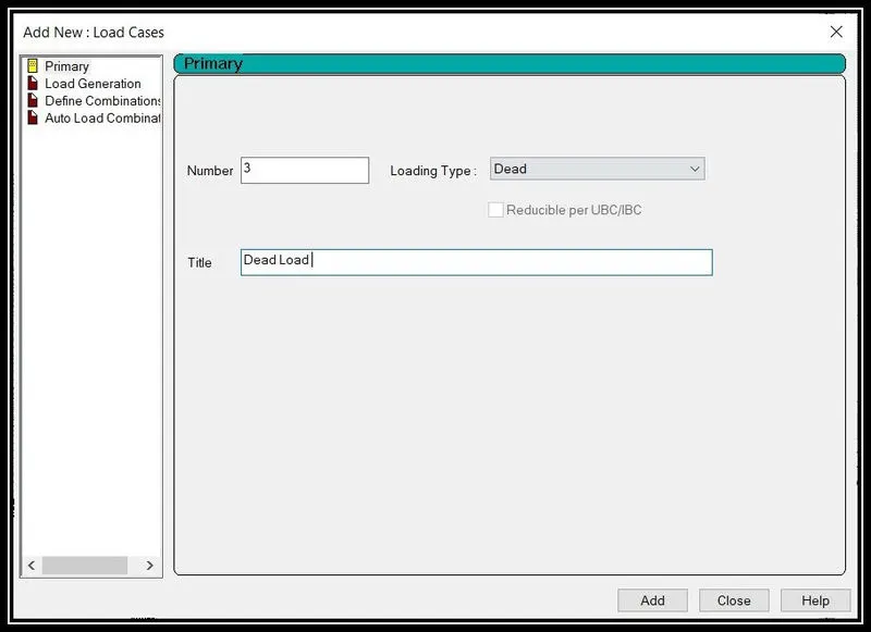
- The select that load case and click on add option.
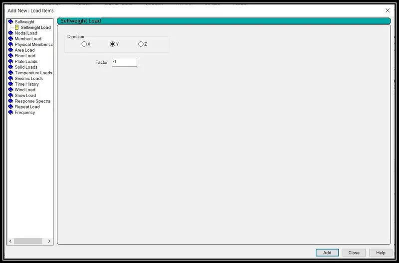
- Add selfwt factor and then select that factor and assign it to all structure.
C) Live Load
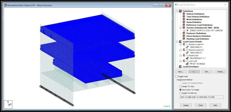
We have to provide live load of 10 kN/`m^2` on all the slab
- So create one load case as Live load.
- Select that load and then click on add option then this window will open.
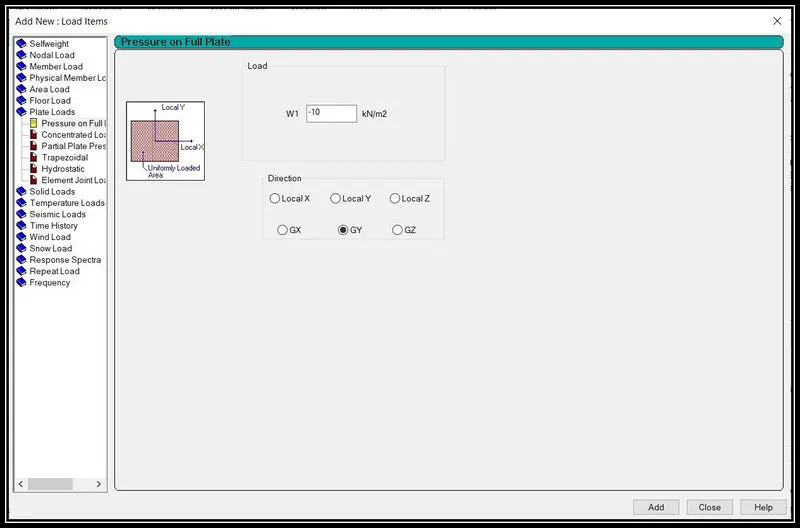
- In above window select plate load and add the value of live load in W1 as -10 than select direction as GY
- Then click on add button.
- After that select that live laod and assign it on the all three slab. (Top,middel and platform slabs)
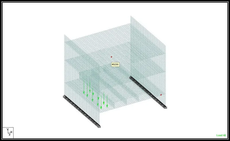
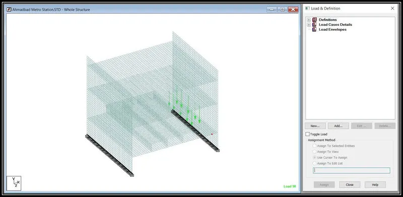
D) IRS live Loading
We have to create metro live loading on the structure.
- First we need to define the vehical load.
- For that select vehical defination option in load and defination window then vehical defination window will open.
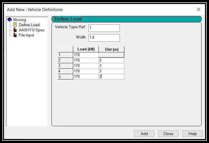
- Define Load according to above window and then click on add button.
- After that click on load case detail and again click on add button.
- Than LoadCase window will open.
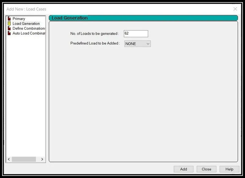
- In above window select load generation than add 62 nos of load in that box and click on add button.
- After that select that generated load and click on add button new load case window will open.
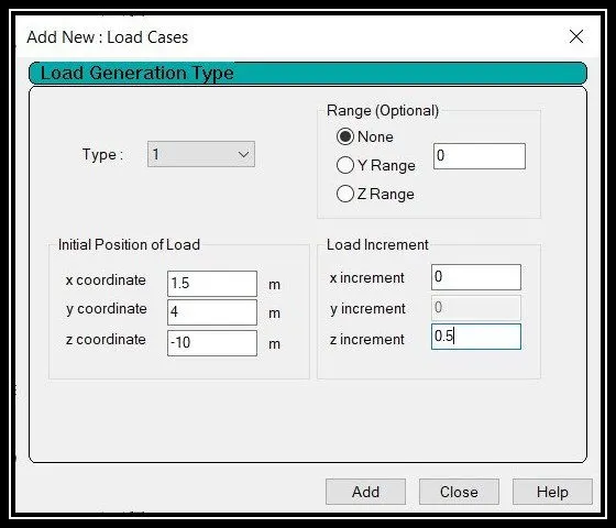
- Put coordinate where from train is coming and than click on add button.
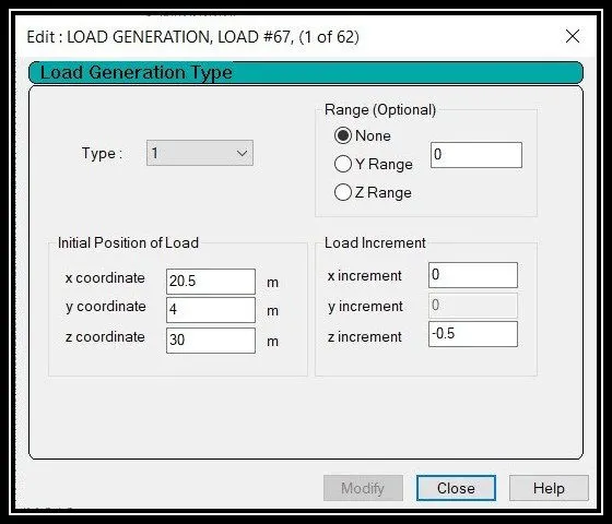
- Repeat same procedure in another direction .
- Generate new load case for different platform
- Coordinate for another platform is differen which shown below.
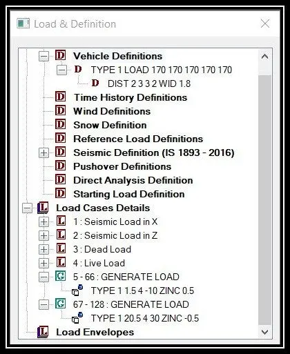
- Loading and definition of IRS live loading
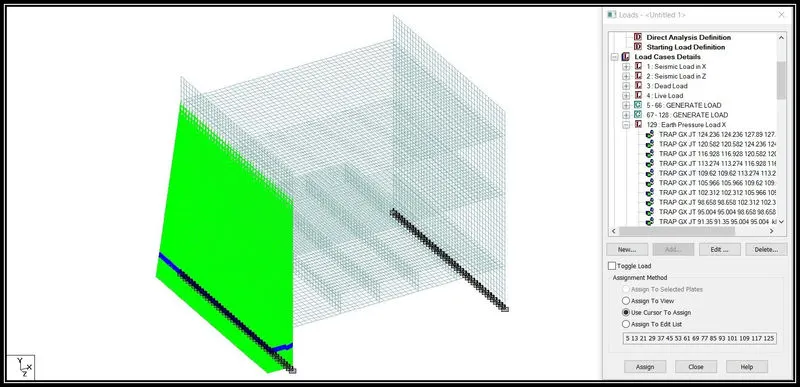
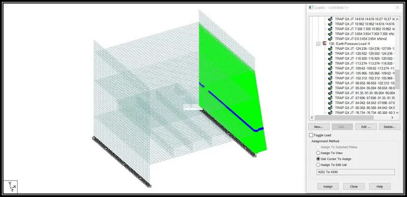
E) Earth Pressure Load
Earth pressure load we calculated above mannual
- For applying earth pressure loading.
- First we need to create a two load case for Earth pressure loading. which is in X and -X direction.
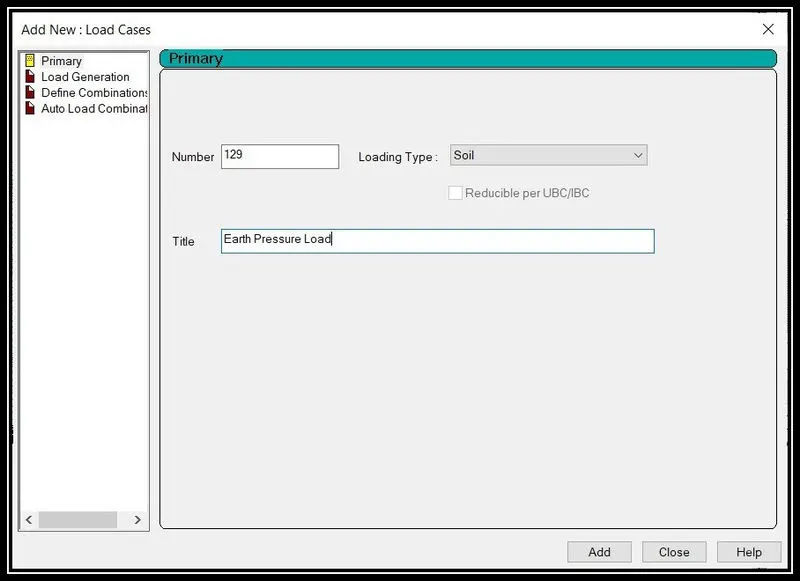
- After that select that load and click on add button then this window will open.
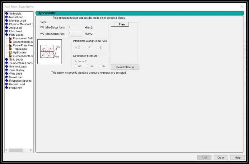
- In above window click on select plate option.
- Then select the plate of first wall.
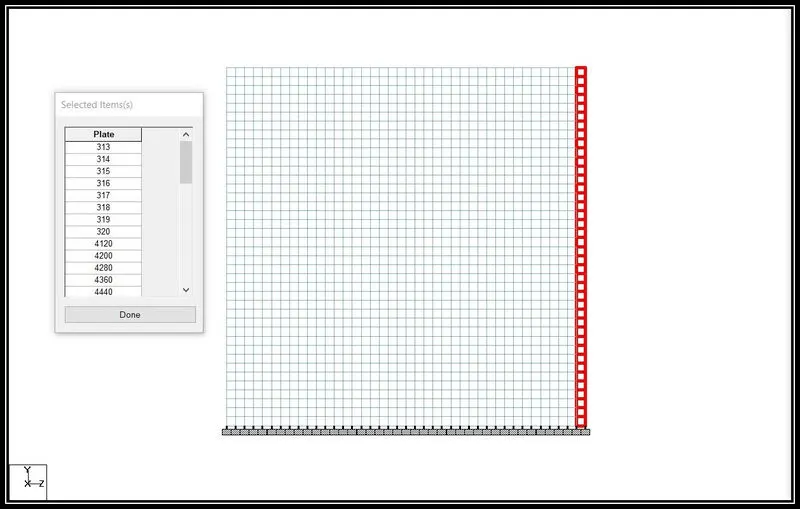
- Then Click on done button than again this window will open.
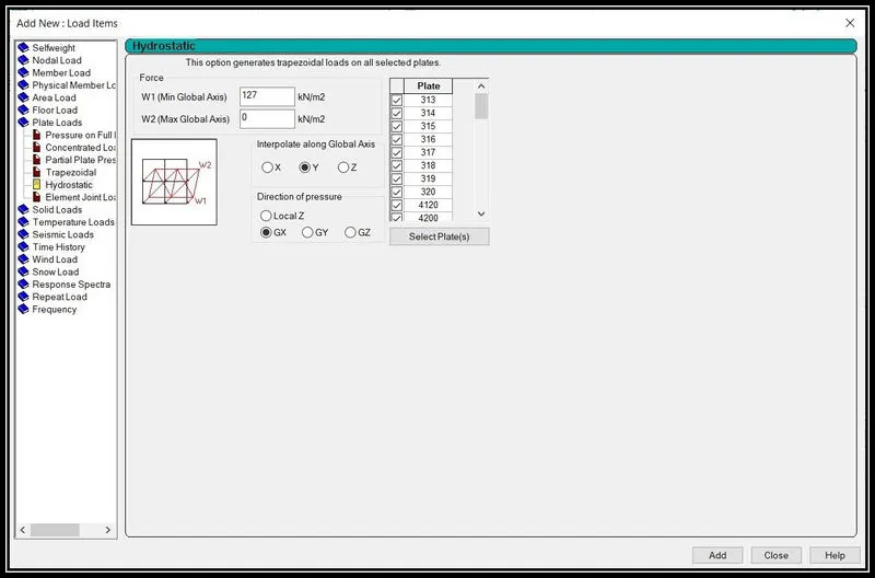
- In above window put the value of W1 as 127 kN/`m^2` which we calculate above mannualy
- And select global axis as Y and direction of pressure is GX and then click on add to apply.
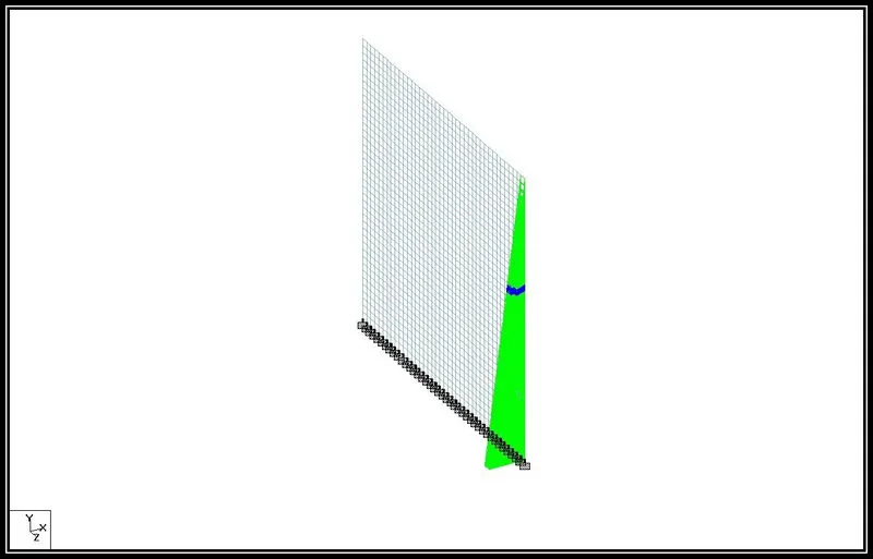
- For applying earthe pressure load full plate.
- Select induidial plate one by one and assign this load on structure.
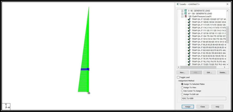
- Repeat same procedure for wall 2
- Value of W1 is -128 and direction are same.
F) Wind Load
Wind Load is acting on top wall of the structure.
- For Appling wind load first create the two load case which is in X and - X direction.
- Then select that case and cilck on add button then this window will open.
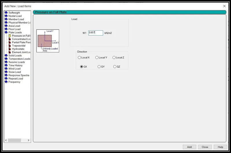
- In above window select plate load in that select pressure on full plate.
- Then put the value of W1 as wind pressure which we calculated above and click on add button.
- Then select that load and assign it to the plate.
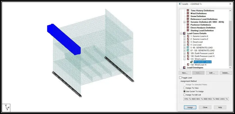
- Repert same procedure for different wall
- Use value of W1 is -0.657 becaue wind is coming from inverse direction.
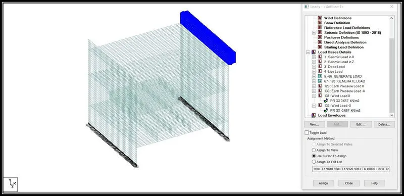
- Hence all load is assign to the structure.
All Load On Structure

Step (4) :- Performing analysis.
- For Anlaysis of the structure go to Analysis And Design option.
- In that click on run analysis option to start the analyis
- Then this window will shown after successfull analysis is done.
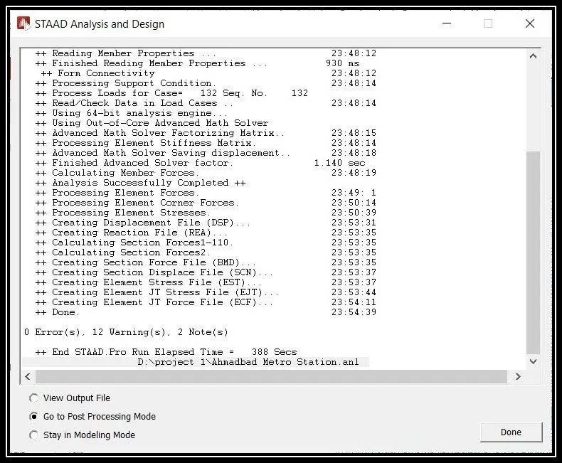
- For the result click on post processing mode to view.