Week 12 Challenge
Aim :- To create truss bridge model and applying barge impact load on it and perform analysis using Staad.pro software.
* Manual calculation *
Given data :-
- (W) The Dead weight tonnage of Panamax vessel is 52500 DWT.
- (V) = 60 km /hr -- 16.67 m/sec.
- (CH) =1.25.
- (L) Span of the Bridge is 12m.
- (B) Width of the bridge is 7m.
- Piers of size 2.5 m x 2.5m.
- The cross Girders size 0.75 m x 1.8 m.
- The Deck slab is 500 mm thick.
Calculation of barge impact :-
Barge collision energy.
KE = 500 X CH X W X `(V)^2`
= 500 X 1.25 X 52500 X `(16.67)^2`
= [ 9118229531 ]
Barge damage depth 'aB'
ab = 3100 X [ (1 + 1.3 X `10^-7` X KE )0.5 - 1 ]
= 3100 X [ (1 + 1.3 X `10^-7` X 9118229531 )0.5 - 1]
= [ 103675.5316 mm ]
Barge Collision Impact force Pb
Pb = 6.0 X `10^6` + 1600 X (ab)
= 6.0 X `10^6` + 1600 X 103675.5316
= 171880850 N
= 171880 KN.
Uniform Force
= Pb / length of bridge
= 171880 / 12
= 14323 kN/m
* Analysis using Staad.pro software *
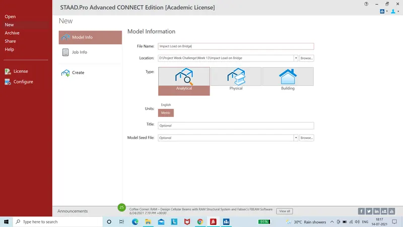
Step (1) :- Opening of Stadd.pro software
- Fill all inforation about model.
- Then click on create to open the model.
Step (2) :- Creating Truss bridge model.
- Create the first node using the cordinate.
- Now we need to create first cross beam of bridge
- For that select that first node using node cursor and copy it in Z direction upto 7 meter (Width of the bridge Given) using translational repeat option
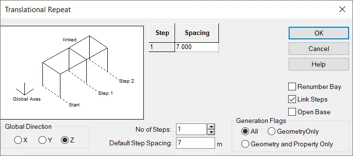
- In translational repeat option select direction as Z and spacing should be 07 and also click link steps option to connect both the node then click on Ok to creat the cross beam.
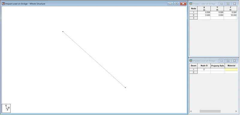
- Lenght of the bridge is given 12 meter.
- So select that beam using beam cursor and copy it in X direction using translational repeat option.
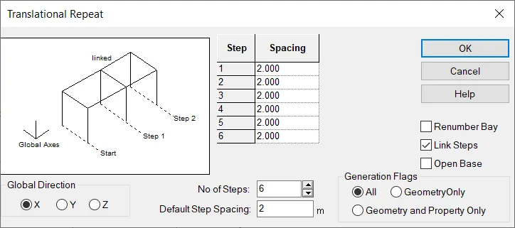
- In translational repeat option select direction as X and spacing should be 2 meter and No of steps 6 nos.
- Also click on link steps to connect all the cross beam.
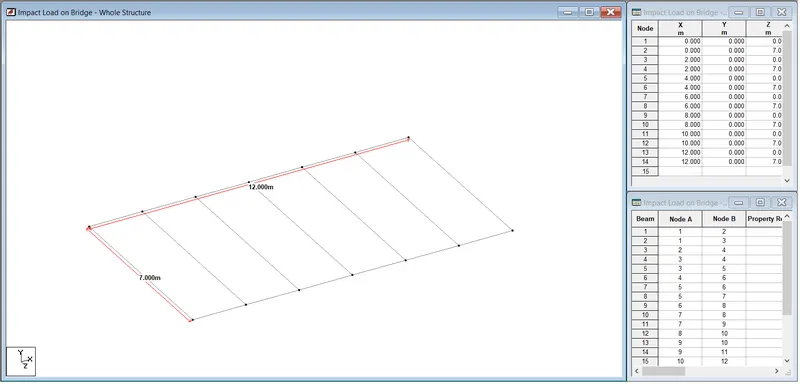
- Then Creating pier in model
- For creating pier fisrt select all four ending node of cross girder and copy them in Y direction using translational repeat option.
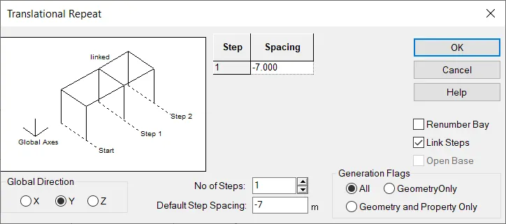
- In Translational repeat option select direction as Y and spacing should be -7 meter assumption (because we are copying node in inverse direction)
- No of step should be 1 and aslo select link steps option to connect both the node then click on OK to create.
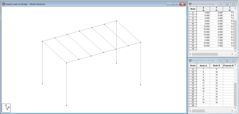
- Creating vertical member.
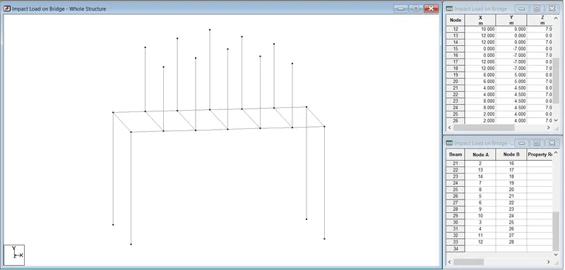
- For that select both side node of middel cross beam and copy them in Y using translational repeat option upto 5 meter.
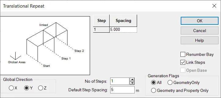
- In translational repeat option select direction as Y and spacing is 5 meter and also click on link steps to connect both the node than click on OK to create.
- Repeate same procedure for another cross beam .
- But put variation in spacing.
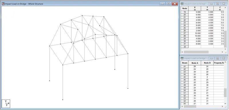
- After that connect all the node using add beam option.
- For that first go to geomertry in that select add beam option then connect all the node like wise shown in question.
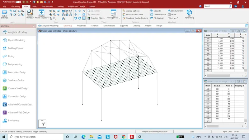
- Creating deck slab for bridge.
- Select first node on crossbeam and copy them in X direction upto 0.5 meter using translational repeat option.
- Again select both the node and copy it in Z direction upto 0.5 meter using translational repeat option.
- After that adding plate to that node which we created for that go to geometry option in that select add plate option and connet all 4 node using this.
- Hence one plate is created.
- Then select that plate using plate cursor and copy it in X direction using translational reapeat option.
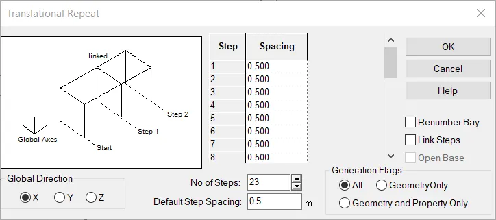
- In teanslational repeat option select direction as X and spacing should be 0.5 Meter.
- And no of step is 23 nos, lenght of the bridge is 12 m so 12/0.5 = 24 , 24-1= 23 nos then click on OK to create.
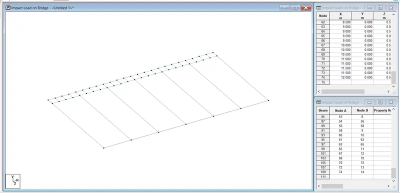
- Againg select all the plate using plate cursor and copy them in Z direction using translational repeat option.
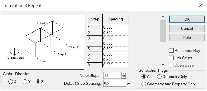
- In above windown select direction as Z and spacing is 0.5.
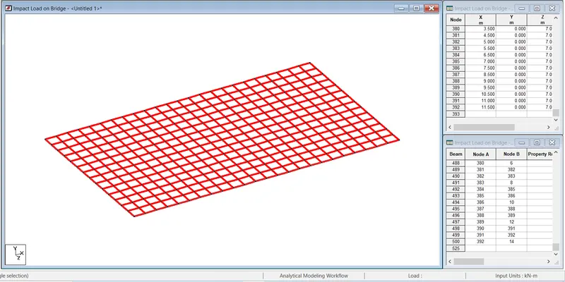
- Width of bridge is given 7 meter so no of step should be 13 nos, 7/0.5=14, 14-1= 13 nos.
- Adding support to the piers.
- For adding support first go to specification then select fixed support option.
- Then one window will open in that window click on add option.
- After that suppot window will open.
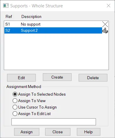
- In above window click on support 2 option and select all button node of all the piers and then click on assign button to add the support.
- Hence support is assign to all the piers.
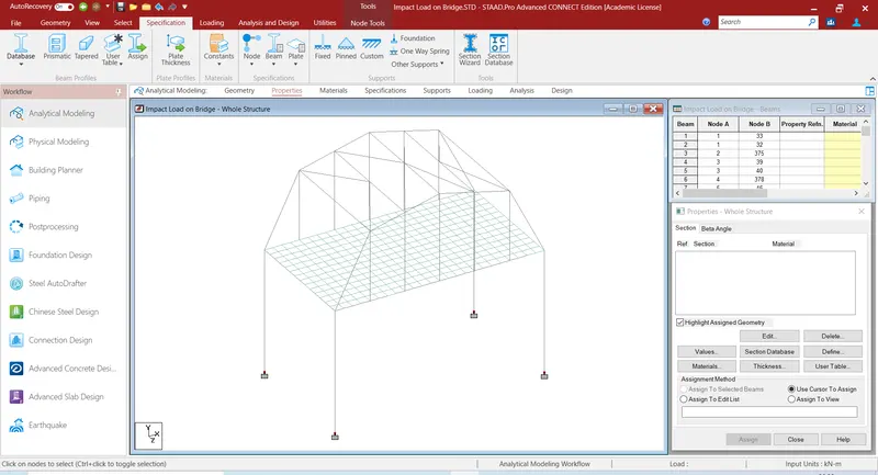
Step (3) :- Assigning property to the structure.
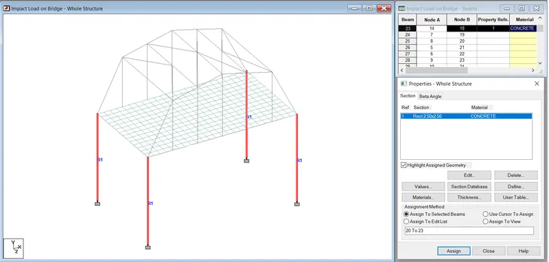
- Adding property to the structure.
- For assigning proprty first go to specification then click on prismatic option then property window will open.
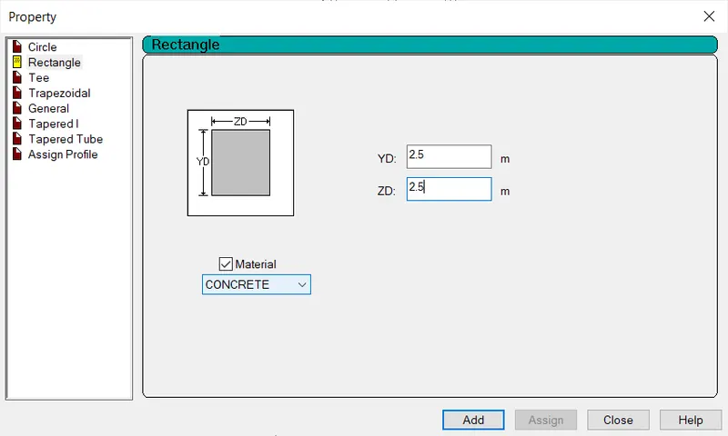
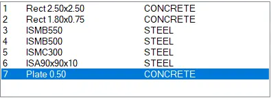
- Instert the value of piers as 2.5 X 2.5 M which is given in question then click on add option.
- After select all the pier using beam cursor and assign this proprty to it.
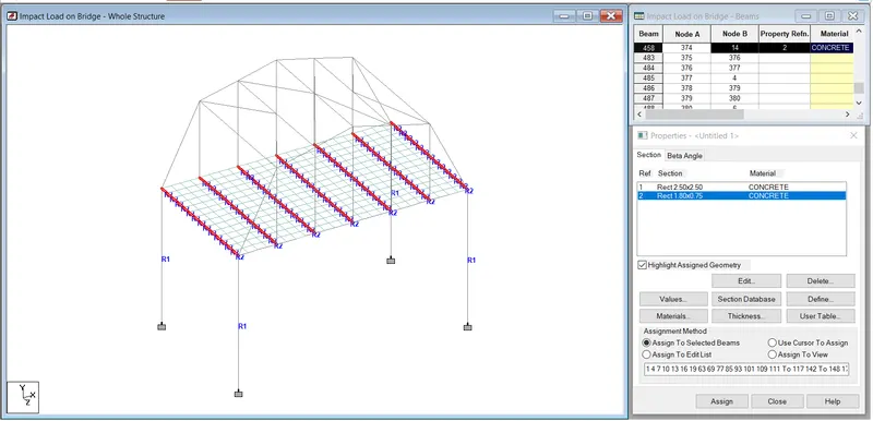
- Adding property to the crossgirder.
- Repeat same procedure as above.
- In property window put value of cossgirder as 0.75 X 1.8 metre as also mention in question.
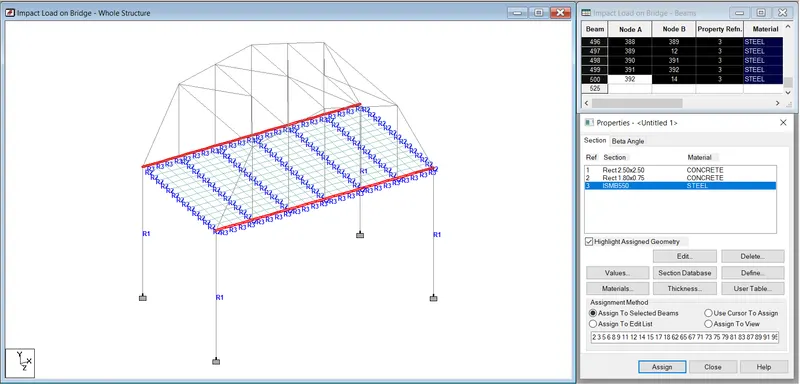
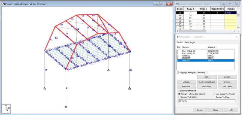
- For main girder assume S shape property as ISMB 550
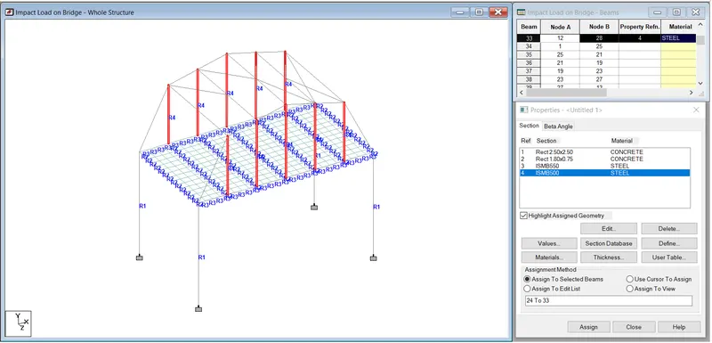
- For vertical component of bridge truss assume property as ISMB 500.
- For top chord and strut component of bridge assume property as ISMC 300
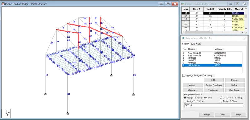
- For top lateral bracing assume angle property as IAS 90X90X10
- Adding propery to deckslab.
- For that go to specification then click on plate thickness after that plate property window will open.
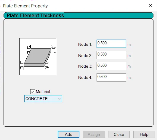
- Assign 500 mm thickness of deckslab then click on add.
- Select the deckslab using plate cursor and assigned this property to it.
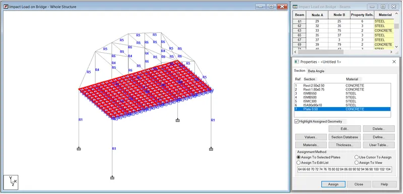
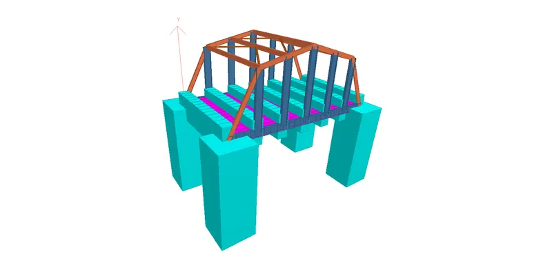
3D Model
Step (4) :- Assigning barge impact load to the structure.
- For assigning barge impact loading to the sturcture go to loading option.
- In right side of the window load & defination window will shown.
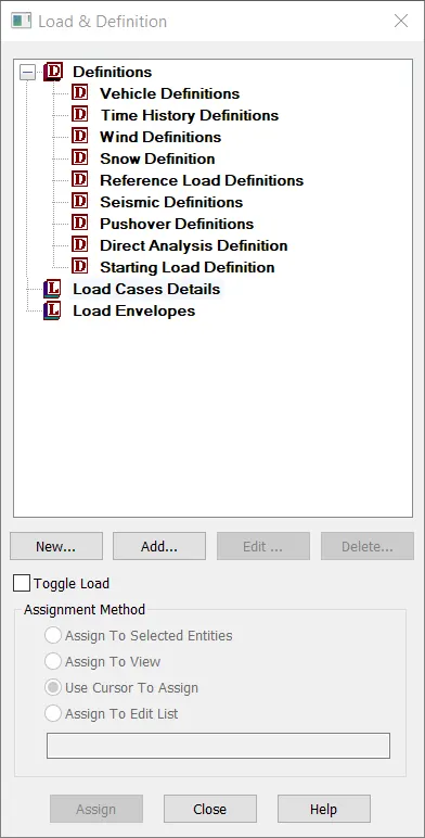
- In above window create load case 1 as barge impact load.
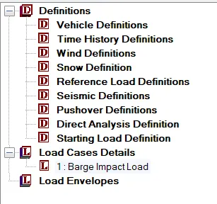
- Select that load which we created and then click on add option.
- After that this window will open.
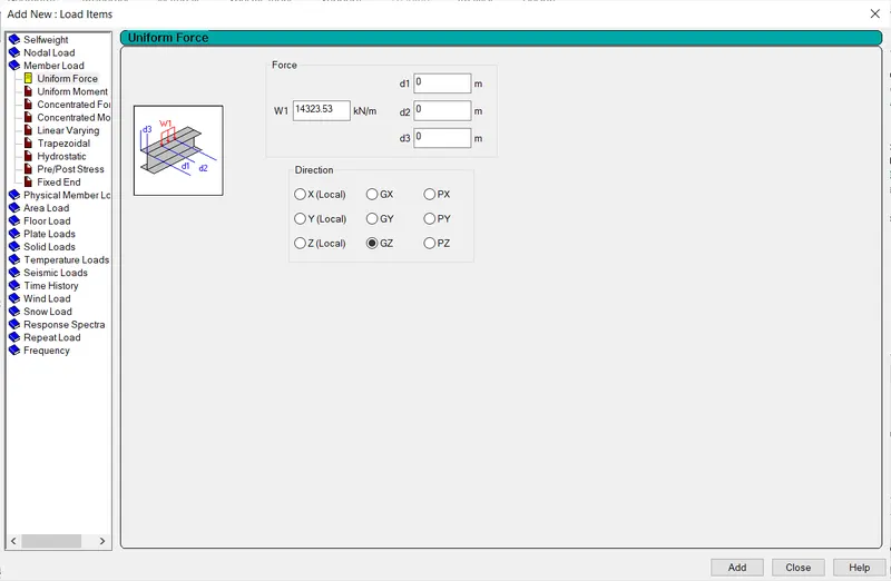
- In above window select member load in that select uniform force and insert that W1 as 14323.53 kN/m ( Barge Impact force) and also select direction as GY then click on add option.
- Then select that load and assign to the structure.
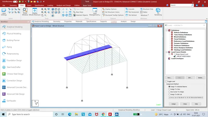
Step (5) :- Analysis of model.
- Go to analysis and design option than click on run analysis option.
- Then analysi process will start.
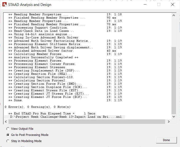
- To view the result select post prossing mode in above window and click on done option.
Result :-
A) Bending moment diagram
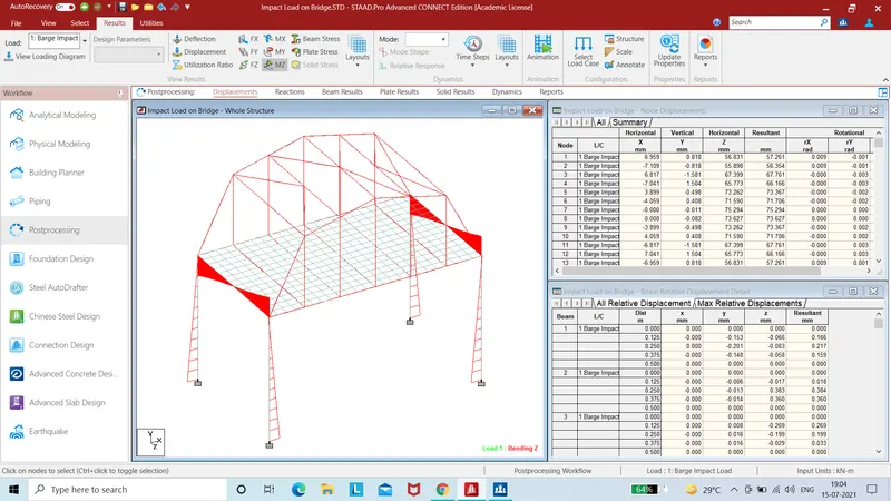
B) Deflection diagram
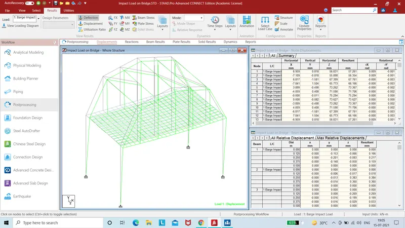
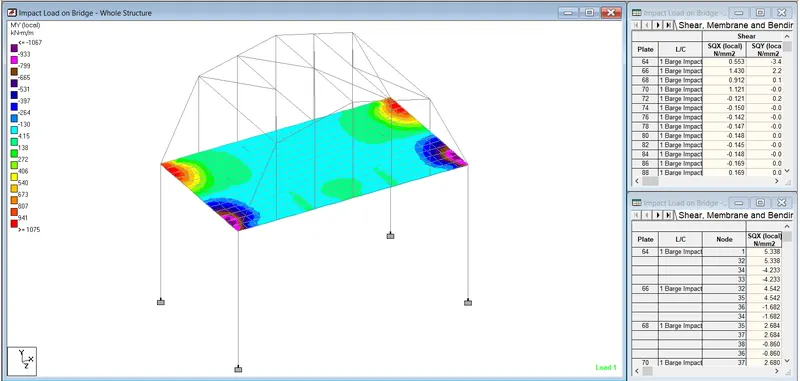
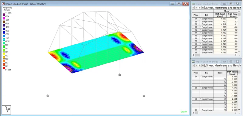
C) Plate stress in MY and MX