Project 2
Aim:-
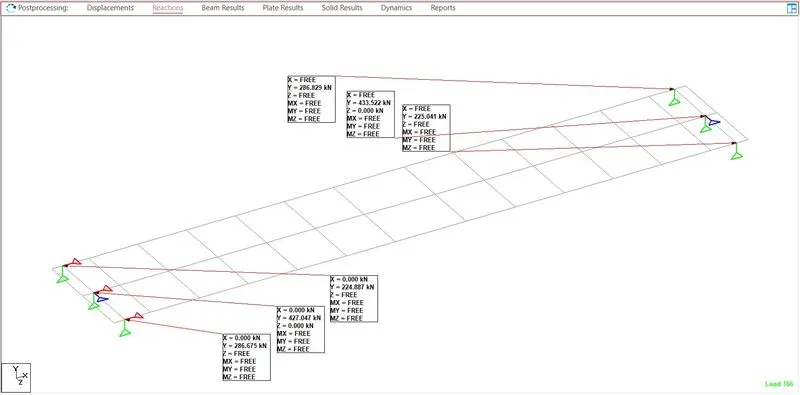
Que (1):- From the grillage model for I-Girder (Longitudinal Analysis of 3 X 25 Meter Prestressed I-Girder) modeled in project 1 extract the reaction and answer the following Question)
Answer:-
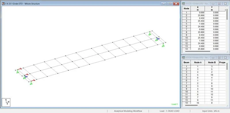
- Staad Model
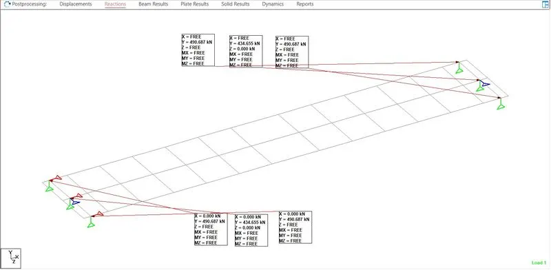
- Dead Load reaction
Maximum Y = 490.687 kN , Minimum Y = 434.655
Y= 51 T
Rotation = 0.004 rad
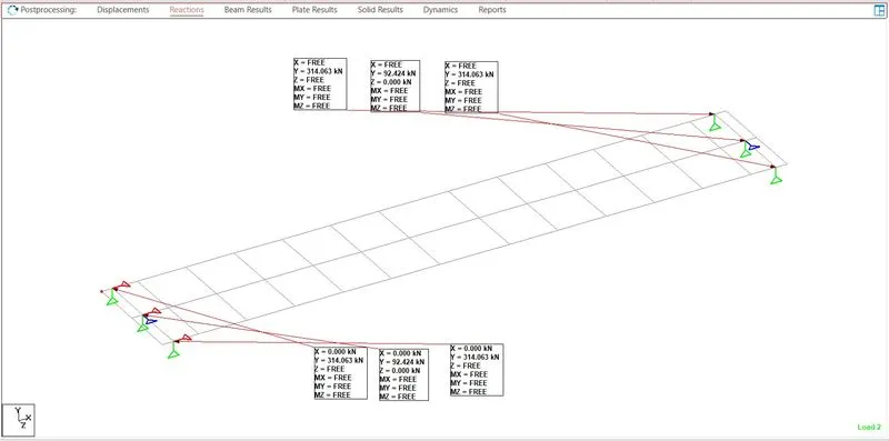
- SIDL reaction
Maximum Y = 314.063 kN , Minimum Y = 92.424
Y = 33 T
Rotation = 0.002 rad
- Live Load Reaction
Maximum Y = 433.522 kN , Minimum Y = 224.887
Y = 45 T
Rotational = 0.002 rad
Que (2):- Design the elastomeric bearing with the given design parameter.
Answer:-
| Design Parameter | ||||
| Span Length | L | = | 25.9 | m |
| Bearing to Bearing Length | Lo | = | 25 | m |
| Young's modulus of concrete for M60 | E | = | 36000 | Mpa |
| Static Shear modulus of elastomer | G | = | 0.9 | Mpa |
| Dynamic Shear modulus of elastomers | Gs | 1.8 | Mpa | |
| Inertia os section ( I Beam only ) - At mid span | I | = | 0.27835 | m4 |
| Inertia os section ( I Beam+Slab ) - At mid span | I | = | 0.62468 | m4 |
| Max reaction due to total dead load ( From Grillage Model) | PDL | = | 51 | T |
| Max reaction due SIDL ( From Grillage Model) | PSIDL | = | 33 | T |
| Max reaction due Live Load + Impact ( From Grillage Model) | PLL | = | 45 | T |
| Maximum rotation due to live load ( From Grillage Model) | αLL | = | 0.002 | rad |
| Rotation due to ( DL + Slab + X-girder) ( From Grillage Model ). | αDL | = | 0.004 | rad |
| Rotation due to ( SIDL ) ( From Grillage Model ). | αSIDL | = | 0.002 | rad |
| Creep Coefficient | ecr | = | 4.30E-05 | /Mpa |
| Translation due to Creep | ucr | = | 7.28 | mm |
| Shrinkage coefficient | eSH | = | 3.00E-04 | |
| Translation due to shrinkage | USH | = | 4.05 | mm |
| Coefficient of thermal expansion | eT | = | 1.17E-05 | |
| Translation due to thermal expansion | UT | = | 5.53 | mm |
| Translation due to BR/TR= F/K ( K = Stiffness of bearing = G*A/T) | UBR/TR | = | 11.33 | mm |
| Max translation (+) = UT + UBR/TR | Umax (+) | = | 16.86 | mm |
| Max translation (+) = Ucr + USH + UT + UBR/TR | Umax (-) | = | 28.19 | mm |
| Design Data | ||||
| Dead Load | PDL | = | 490687 | N |
| SIDL | PSIDL | = | 314063 | N |
| Total Slow Vertical Load | PC | = | 804750 | N |
| Rapid Max Vertical Load | Psmax | = | 0.00 | N |
| Rotation in Longitudinal direction. due to slow loads | αc | = | 0.01 | rad |
| Rotation in Longitudinal direction. due to rapid loads | αs | = | 0.00 | rad |
| Rotational due to position tolerance | αo | = | 0.00 | rad |
| Translation in Longitudinal direction. due to slow loads | UC | = | 16.86 | mm |
| Translation in Longitudinal direction. due to rapid loads | US | = | 0.00 | mm |
| Total Translation in Longitudinal dir. | U | = | 16.86 | mm |
| Dimensioning of Bearing | ||||
| Overall width of bearing in longitudinal direction | a | = | 420 | mm |
| Overall width of bearing in Translation direction | b | = | 420 | mm |
| Thickness of Individual layer of elastomer | ti | = | 12 | mm |
| Thickness of top/bottom layer of elastomer | te | = | 6 | mm |
| Total number of internal layer | n | = | 5 | |
| Thickness of steel laminate | ts | = | 4 | mm |
| Total plan area, A=a*b | A | = | 176400 | mm2 |
| Effective plan area, A' = (a-U) x b | A' | = | 169318.8 | mm2 |
| Total Thickness of Elastomer Bearing | T | = | 72 | M |
| The factor of sefty | ||||
| Factor for serviceability state (SLS) | ||||
| Dead Load | = | 1 | ||
| SIDL | = | 1.2 | ||
| Live Load | = | 1 | ||
| Factors for fracture state (ULS) | ||||
| Dead Load | = | 1.2 | ||
| SIDL | = | 1.8 | ||
| Live Load | = | 1.3 | ||
| Partial safety factor of steel at Limite State | gs | = | 1.2 | |
| Yield Strength of Steel | σa | = | 240 | Mpa |
| Max. Permissible compressive stress in bearing | σo max | = | 11 | Mpa |
| Min. Permissible compressive stress in bearing | σo min | = | 2 | Mpa |
| DESIGN OF BEARING | ||||
| A. Mean Pressure - Serviceability State (Cl.4.3.31) | ||||
| σm = P/A' ≤ 11 Mpa | = | 4.752868553 | Mpa | |
| Where | ||||
| P = PC + PS | ||||
| CONDITION VERIFIED | ||||
| B. No Slip - Serviceability State ( Cl.4.3.3.2) | ||||
| B1 σm mini = Pmini / A ≥ 2.0 Mpa | = | 4.56207483 | Mpa | |
| B.2 H<f*p | ||||
| Enter the type of contact of bearing face with the structure | ||||
| f=0.12+0.2/Sigma m | ||||
| For Slow loads: | ||||
| T>(G *A*Uc) / (0.12 Pc + 0.2A) | T | > | 20.30105119 | mm |
| For Rapid Loads: | ||||
| T>G*A*(Uc + 2Us) / (0.12 Pc + 0.2A) | T | > | 20.30105119 | mm |
| CONDITION VERIFIED | ||||
| C. Limitation of Distortion - Serviceability State (Clausee 4.3.3.3) | ||||
| tH / G ≤ 0.7 | ||||
| or T > ( Uc +Us) / 0.7 | T | > | 24.08571429 | mm |
| CONDITION VERIFIED | ||||
| Fracture State | ||||
| D. No uplift at the edge with the least load - Fracture load ( Clause 4.3.3.4) | ||||
| D.1 tanα < 6∑ eic / a | ||||
| For Internal layer | ||||
| Si = ab / 2ti (a+b) | Si | = | 8.75 | |
| σmc = Pc / A' | σmc | = | 4.752868553 | Mpa |
| eic1 = tiσmc/(4GSi2 + 3σmc) | ∑eic1 | = | 0.19674939 | mm |
| For top & bottom | ||||
| Si = ab / 2te (a+b) | Si | = | 17.5 | |
| eic2 = tiσmc/(4GSi2 + 3σmc) | ∑eic2 | = | 0.051071397 | |
| Total eic ( ∑eic1 + ∑eic2) | ∑eic | = | 0.247820788 | |
| Therefore | 6∑eic/a | = | 0.003540297 | |
| Tanαc = (αc + αo) | tanαc | = | 0.01 | |
| CONDITION VERIFIED | ||||
| D.2 tan αc + 1.5 tan αs < 6∑e1 / a | ||||
| αm = ( Pc + Ps ) / A' | σm | = | 4.752868553 | Mpa |
| For internal layer ei1 = tiσmc/(4GSi2 + 3σm) | ∑ei1 | = | 0.19674939 | mm |
| For top & bottom layer ei2 = tiσmc/(4GSi2 + 3σm) | ∑ei2 | = | 0.051071397 | |
| 6∑ei/a | = | 0.017701485 | ||
| tanαc + 1.5 tanαs | = | 0.0100 | ||
| CONDITION VERIFIED | ||||
| Shear and strength of plate | ||||
| E. No buckling ( Clause 4.3.3.5) | ||||
| a/10 ≤ T ≤ a/5 | ||||
| T | = | 72 | mm | |
| a/10 | = | 42 | mm | |
| a/5 | = | 84 | mm | |
| CONDITION VERIFIED | ||||
| F. Shear - Servicebility State ( Clause 4.3.3.6) | ||||
| tp + th + ta < 5G | ||||
| tp = 1.5 ( PC + 1.5 Ps ) /(Si a b) | tp | = | 0.782069971 | Mpa |
| tH = ( GUC +GsUs) / T | tH | = | 0.21075 | Mpa |
| ta = G a2 ( tanαc +1.5tanαs) / (2 T ti ) | ta | = | 0.91875 | Mpa |
| tp+tH+ta | = | 1.911569971 | Mpa | |
| 5G | = | 4.5 | Mpa | |
| CONDITION VERIFIED | ||||
| G. Strenght of Plate - Fracture State ( Clause 4.3.3.7) | ||||
| ts > a/Si . Sm/Sa. Gs | ||||
| a/Si | = | 48 | mm | |
| σm / σs | = | 0.019803619 | ||
| gs | = | 1.2 | ||
| a/Si.Sm/Sa.gs | = | 1.140688453 | mm | |
| ts | = | 4 | mm | |
| CONDITION VERIFIED | ||||
Que (3):- From the model determine the axial loads (reaction) and moments in the longitudinal and transverse direction at the base of the pier (DL, SIDL, LL). Using those values calculate the design BM and design SF for the design of the open foundation in both directions.
Answer:-
Calculating Total Load "P" at Pier bottom
- Total Dead Load calculation from model
| Dead Load | |||
| Right Side | Left Side | ||
| 490.687 | 490.687 | ||
| 434.655 | 434.655 | ||
| 490.687 | 490.687 | ||
| Total | 1416.029 | 1416.029 | 2832.058 kN |
289 Ton
- Total SDIL calulation from model
| SIDL | |||
| Right Side | Left Side | ||
| 314.063 | 314.063 | ||
| 92.424 | 92.424 | ||
| 314.063 | 314.063 | ||
| Total | 720.55 | 720.55 | 1441.1 kN |
147 Ton
- Total Live load calculation from model
| Live Load | |||
| Right Side | Left Side | ||
| 224.887 | 286.829 | ||
| 427.047 | 433.522 | ||
| 286.675 | 225.041 | ||
| Total | 938.609 | 945.392 | 1884.001 kN |
193 Ton
- Calculating the Self weight of pier cap
Considering rectangular shape pier cap
Where
Lenght = 5 meter , Breadth = 2 meter , Height 1.8 Meter
Weight of the pier cap is = 5 x 2 x 1.8 x 2.5
= 45 T
- Calculating Selfweight of the pier
Considering circular shape pier
WherThe diameter
Diameter of the pier is 1.2 Meter, and Length is 10 Meter
Weight of the pier is = 1.13 x 10 x 2.5
= 28.28 T
Total Load on Pier bottom
= [ 289 + 147 + 193 + 45 + 28.28 ]
P = 702.28 T
Calculating Longitudinal Moment (ML)
Dead Load
ML = ( 144.5 x 0.45 ) - (144.5 x 0.45)
= 0 T
SIDL
ML = (78.5 x 0.45) - (78.5 x 0.45)
= 0 T
Live Load
ML = (95.72 x 0.45) - (96.41 x 0.45)
= 0.3105
Total Longitudinal Moment (ML) at pier bottom
= [ 0 + 0 + 0.3105 + 45 + 28.28 ]
ML = 73.60 Calculation
Claculation Transverse Moment (MT)
From the above calculation refrences MT = 0 T
We have the Total load, total ML and MT at pier bottom
Therefore
| P (T) | ML (T) | MT (T) |
| 702.25 | 73.6 | 0 |
We Refer Foundation parameter from the Vilectureture
| A1 | 5.25 | m2 |
| A2 | 81 | m2 |
| Total weight of foundation | 455.6 | T |
| Area of foundation | 81 | m2 |
| ZL or ZT | 121.5 | m3 |
Governing Load Case
| P(t) / A | ML / ZL | MT / ZL |
| 8.669753 | 0.605761 | 0 |
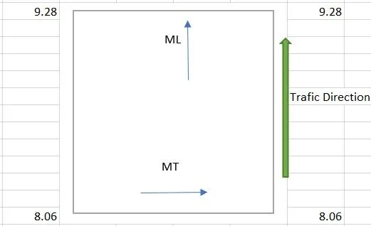
Adding self-weight of the footing in a bove value so we get
= 9.28 + 5.62 :- 14.90
= 8.06 + 5.62 :- 13.32
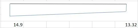
- Bending Moment at the face of the pier
= `(14 xx (3.25^2)/2+ (14.9-14)/2 xx 3.25 xx 2/3xx3.25)xx8`
= 616.85 t-m
- Shear Force at d Distance from the Face of pier (Per Meter)
=`14.25 xx (3.25-2.25) + (14.9-14.25)/2 xx (3.25 - 2.25)`
= 14.575 t-m
Que (4):- Calculate the load at the base of the pier - Wind, Seismic, LWR, Breaking and Centrifugal force with the following data.
Loacation of the metro viaduct - Chennai
Height of the pier = 10 M
Speed of the train = 75 km/h
Radius of curvature = 1000 m
Answer:-
- Wind Load
- This load comes into play when wind applied force on the structure.
- In this case the wind pressure will be normal, allowing the movement of live load.
`Vz = Vb xx K1 xx K2 xx K3`
Where,
Vb (m/s) is regional basic wind speed.
K is tarain factor
Calculation of wind load is based on IS-875 (part 3) - 1987
The design wind speed at heighis consideredider as followed:
`Vz = Vb xx K1 xx K2 xx K3`
Vb(m/s): Regional basic wind speed, taken 50 m/s for Chennai City
| General Parameters | ||||||
| Total Structure Height above ground | H | = | 10 | |||
| Regional Basic Wind speed | Vb | = | 50 | |||
| Probability Factor | K1 | = | 1.08 | |||
| Terrain Height & Structure size factor | K2 | = | 0.82 | Category 3 Terrain, | ||
| Topography Factor | K3 | = | 1 | |||
- Design Wind Speed at Height z,
`Vz = Vb xx K1 xx K2 xx K3`
`Vz = 50 xx 1.08 xx 0.82 xx 1`
= 44.28 m/s
Wind Pressure,
`Pz = 0.6 xx Vz^2`
`Pz = 0.6 xx 44.28^2`
= 1176.44 N/m2
= 0.119 t/m2
- Seismic Load
- This load comes into play during earthquake, when the structure vibrate in the longitudinal direction.
- Live Load is not consider in the consider in this case as vibration don't have any impact on the live as it rolls away
Seismic Acceleration :- Ah = (Z/2) x (I/R) x (Sa/g) , Where:
Ah = horizontal seismic coefficient to be considered in design
Z = Zone factor = 0.16 (For Chennai)
I = Importance factor = 1.50
R = Response reduction factor
= 4 , for pier
Sa/g being computed as per IRC 6 :2017 for medium soil site
Mathematical expression are:
Sa/g = 1 + 15 T for 0.0 < T < 0.10
Sa/g = 2.5 for 0.10 < T < 0.55
Sa/g = 1.36/T for 0.55 < T < 4.00
- LWR Force
- The "Long Welded Rail" force acts on the structure due to the stresses generated in the railz
- It is generated by the expansion/contraction of the rail due to increase/decrease in temperature.
- LWR force are consider to be 0.8 t/m/track
Longitudinal LWR force = 0.8 t/m/track for two Track
Transverse force on the pier due to LWR : F [ `DeltaT` * `alpha` * Arail * Erail ] * [ no of rail ] * [ span length ] / R
where,
`DeltaT` = Temperature difference = 34 degree
`alpha` = Temperature coefficient = 1.17E-0.5 per degree
Arail = Area of one rail = 200000 MPa
Erail = Elastic modulus of rail = 7670 mm2/Rail
Number of Rail = 3 nos
Span lenght, Span 1 = 25 M
Span 2 = 25 M
Radius off Curvature = 100000
Transverse force acting @ Rail Level LWR = [ `DeltaT` * `alpha` * Arail * Erail ] * [ no of rail ] * [ span length ] / R
= [ 34 * `1.17xx10^-5` * 200000 * 7670 ] * [ 3 ] * [ 27 ] / 100000
= 45.80 Mpa
- Braking Load
- This Load comes into play when the train applies brakes while moving
- It is taken as 18% of the unfactored vertical loads.
Consider train load as 193 T, So 18 % of 193 = 34.74 kN
- Centrifugal Force
- This load acts on curved span
- It shall be calculated with the actual maximum allowable speed of the train in curve according to plan radius of curvature.
- Coefficient of CF = `V^2/(127xx R)`
Where,
`V^2` is design speed of the train in km/h
`R` is the radius of curve span in meter.
CF = `V^2/(127xx R)`
= `75^2/(127 xx 1000)`
= 0.0454
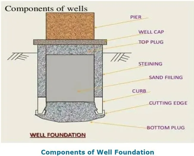
Que (5):- Write in detail about the component of well foundations and the function of each component with relevant drawing
Answer:-
Well, Foundation is the type of deep foundation which is mainly equipped below the water level for bridges. A Well foundation is the same as an open caisson and it can be established on the dry bed or after making a sand island. At locations where the velocity of water is high and the depth of water is higher than 5 to 6 m, wells can be created on the river bank and then floated to the last position and grounded. Much care is needed while grounding a well to assuring that the position of the well is exact. To prevent scour, sandbags are protected around the well. Wells or caissons are large-diameter foundations obtained in underwater conditions such as bridge foundations in rivers. Caissons are large-width foundations that transmit the load of the superstructure through the layer of weak soil to a firm stratum at a significant depth. The well may sink into the river bed by 500 mm to 600 mm under its self-weight. Additional sinking operation is equal to the sinking of wells on the dry bed. The construction of a well foundation is in principle, related to the ordinary wells sunk for obtaining underground water; in fact, it derives its word owing to this construction process.
The following are the component and it's function of well foundation:-
- Staining
Steining is a wall or shall type of structure made up of RCC, and which helps to transfer the load to the curb. It serves as an enclosure for excavating the soil for the penetration of the foundation well.
- Curb
It is an R.C.C. ring beam with a steel cutting edge below. The cross-section of the curb is wedge-shaped which facilitates the sinking of the well. The curb supports well stening. The curb is kept slightly projected from the stoning to reduce the skin friction. Well Curb is a RCC ring beam-type component of well having a steel cutting edge below. Vertical cross-section of the well curb is wedge-shaped, which helps during the well sinking. The curb supports well steining, and the steining is kept slightly projected outer side to reduce the skin friction during well sinking.
- Cutting edge
It is the lowest part of the foundation well, and fabricated in the yard as per approved drawing. Cutting edge shall be fabricated in a number of segments depending upon circumference and ease of handling and transport. Cutting edge helps to cuts the soil during the sinking operation.
- Bottom plug
After completion of sinking, the bottom of the foundation well is plugged with the help of concrete. The well curb confines the bottom plug, and functions like a raft against soil pressure from below.
- Backfill
The well is dewatered after setting of bottom plug concrete, and it is backfilled by sand or excavated approved material. Sometimes water can be used instead of sand/excavated material.
- Top plug
It is a concrete layer of thickness around 500mm, as mentioned in design and drawing. Top plug provided over the filling and inside the well dredge hole.
- Well cap
It is an R.C.C. slab provided at the top of the stening to transmit a load of superstructure to the stening and over which the pier is laid. The minimum thickness of the slab is about 750 mm.