Week 11 Challenge
Aim :- Calculate the temperature load for the RC bridge with M40 grade to be constructed in delhi and perform using STAAD.pro software.
`**`Manual Calculation`**`
1) Maximum temperature in the loacation as per IRC 6 isotherm at the location = 47.5 degree.
2) Minimum temperature in the loacation as per IRC 6 isotherm at the location = -2.5 degree.
`***`Effective temperature difference
= [47.5-(-2.5)]/2 + 10
= 25 + 10
= 35 degree.
`***`Stress due to temperature.
= `alpha` X `Delta T` X E
= `11.27X10^-6` X 35 X 5000 (40) `1/2`
= 12.47 kN/`m^3`
`***`Maximum permissible stress.
=(`2/3`) X 0.7 X `sqrt fck`
=(`2/3`) X 0.7 X (40)`1/2`
= 2.95 kN/`m^2`
Hence,
The stress are restricted to 3 kN/`m^2`
- Maximum Temperature = 47.5 degree.
- Minimum Temperature = -2.5 degree.
- Positive temperature difference
- Temperature at top = 47.5 degree.
- Temperature at buttom = (`2.1/17.8`) X 47.5
= 5.60 degree
`***` This temperature variation is applied as loading in STAAD.pro.
`**` Analyze Using STAAD.pro Software `**`
Step (1) :- Opening of STAAD.pro software.
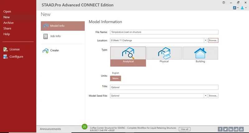
- First open a staad.pro software
- Fill model information regarding structure.
- Then click on create to open a model.
Step (2) :- Creating a Pier in model
- Create a first node using cordinate.
- Select that node and copy it in Y direction upto 10 meter using translational repeat option.
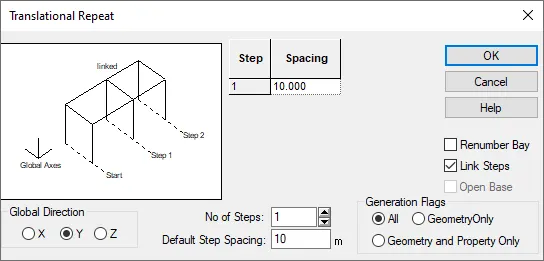
- In translational repeat option select direction as Y and spacing as 10 meter aslo select link step option to connect the node then click on Ok to create.
- Again select the pier using beam cursor and copy it in X direction upto 9 meter using translational repeat option.
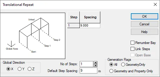
- In above window select direction as X and spacing as 9 meter because length of the span is given in question as 9 meter then click on Ok to create.
- Hence pier is created.
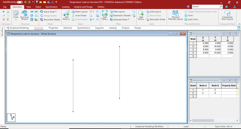
Step (3) :- Creating piercap and girder in model.
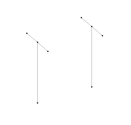
- First we need to create the piercap.
- For creating piercap select both top node of the piers using node cursor.
- Then copy them in inverse Z direction upto 3 meter using translational repeat option.
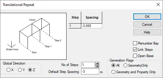
- In translational repeat option select direction as Z and spacing is -3 meter because we copying node in inverse direction.
- Also select link steps option to connect both the node.
- Again select top node of the piers using node cursor.
- And copy them in Z direction upto 3 meter using translational repeat option.
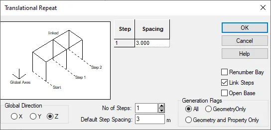
- In above window select direction as Z also spacing is 3 meter click on link step to connect both the node then click on Ok to create.
- :. lenght to the piercap is given in question is 6 meter.
- Hence piercap is created.
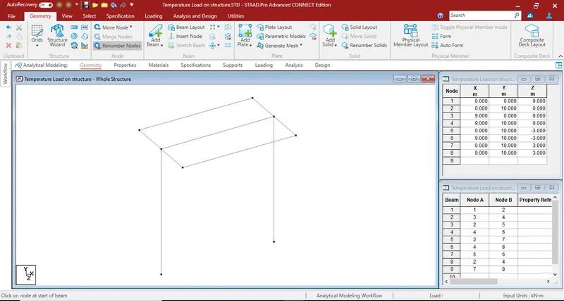
- Now we need to created girder in model.
- For that geometry then click on Add beam option, then cursor will change.
- By using that cursor connect all top node in model which is parallel to X direction.
- Girder is created in model.
Step (4) :- Creating Deckslab
- Creating 7 meter width of deckslab.
- Select first node of the model using node cursor.
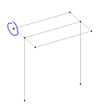
- Copy that node in X direction upto 0.5 meter using translational repeat option.
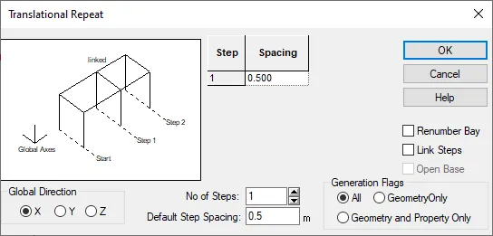
- In above window select direction as X and spacing should be 0.5 meter then click on Ok to copy.
- Again select both the node and copy then in inverse Z direction upto 0.5 meter using translational repeat option.
- Then Add plate in created node, For that go to geometry in that click on add plate option then cursor will change.
- By using that cursor connect all four node and create one plate.
- After that select that plate by using plate cursor and copy it in X direction.
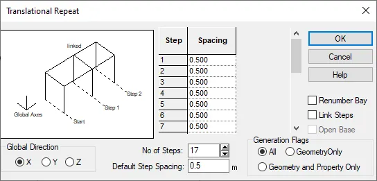
- In transational repeat option select direction as X and spacing should be 0.5 meter.
- No of step is 17 ( :. Span is given 9 meter in question so, 9/0.5=18, 18-1 = '17' no of step) click Ok to copy.
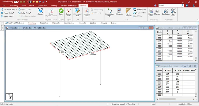
- Again select all the plate by using plate cursor which we created before and copy them in Z direction using translational repeat option.
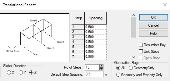
- In translational repeat option select direction as Z and spacing should be 0.5 meter.
- No of step is 13 (:. Width of the deckslab is given 7 meter so, 7/0.5=14, 14-1= '13' no of step) click Ok to copy.
- Hence deckslab is created.
Step (5) :- Assigning support to the pier.
- First go to specification in this menu click on Fixed support option.
- Then support window will open.
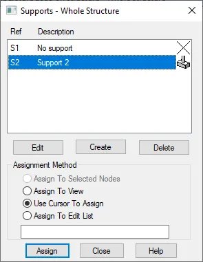
- In above window first select support then select buttom node of the pier after select assign to selected node option then click on Assign button to created the support.
- Hence, support is assign to the structure.

Step (6) :- Assigning property to the pier.
- For that first go to specification then click on prismatic option then property window will open.
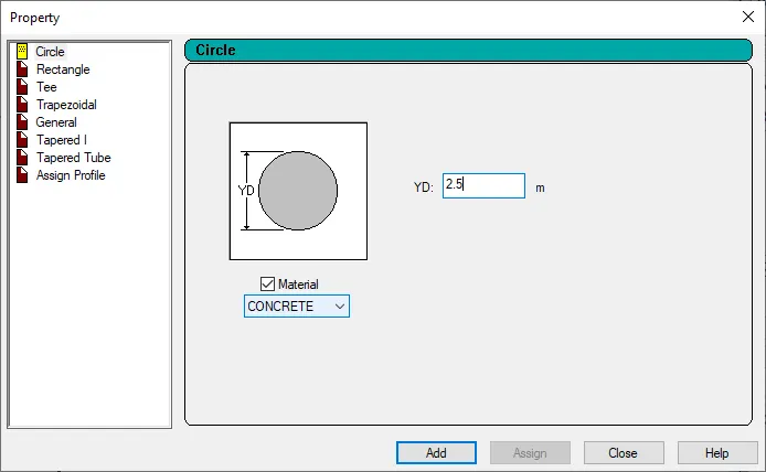
- In property window select circle and put diameter of circle as 2.5 meter which is given in the question.
- Then click on Add button.
- After that select both the pire using and assign this property to it.
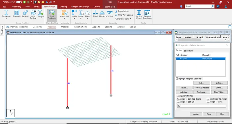
Step (7) :- Adding property to the piercap.
- Go to specification then click on prismatic option then property window will open.
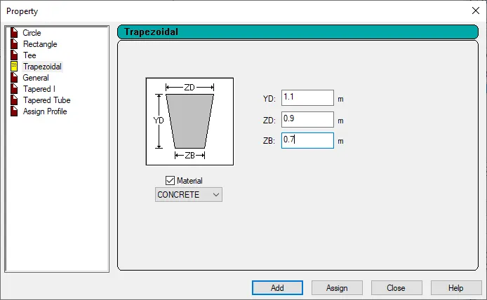
- In above window select trapezoidal then assume the size of piercap like above window then click on Add.
- Select both the pier cap and assign this property to it.
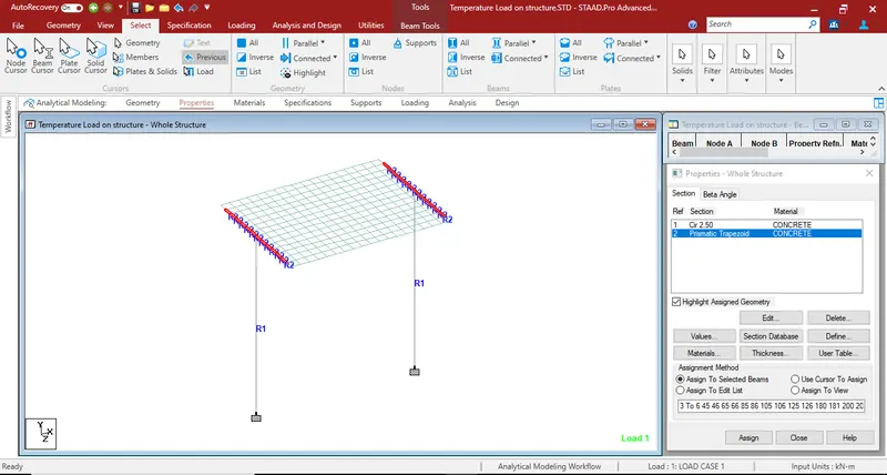
Step (8) :- Adding property to the box girder.
- Repeat same procedure as mention in step 6.
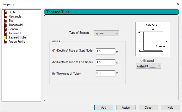
- In above window select tapared tube section and also select square type section.
- Put the size girder as mention in above window then click on add.
- Select all the girder and assign this property to it.
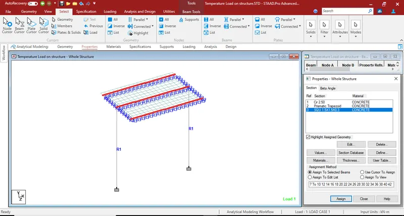
Step (9) :- Adding and assigning plate thickness to the deckslab.
- First go to specification then click on plate thickness option, then property element window will open.
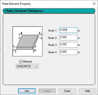
- Put plate thickness as 0.550 meter in above window which is given in question, then click on add.
- Select all the plate using plate cursor and assign this property to it.
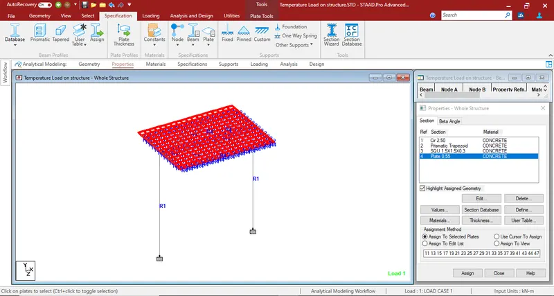
[ 3D Model ]
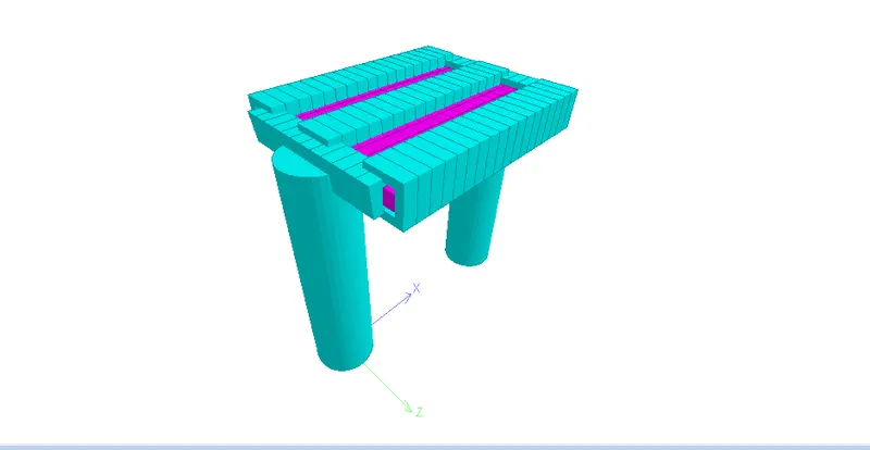
Note :- Crosscheck the model which we created is correct or not (:. Multiple structure, Missing property , Duplcate thing)
Step (10) :- Applying Temperture Load on structure.
- First go to loading option in right side of the window then this window will shown.
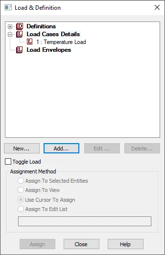
- In above window click on load cases details and create load case 1 as temperature load
- After creating load case select thet load case and click on add button then this window will open.
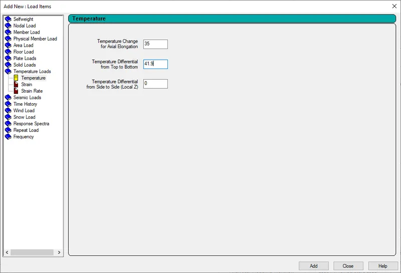
- In this window select temperature load and put all the load as we calculated earlier manually and click on add.
- Then select that load and assign to the structure model.
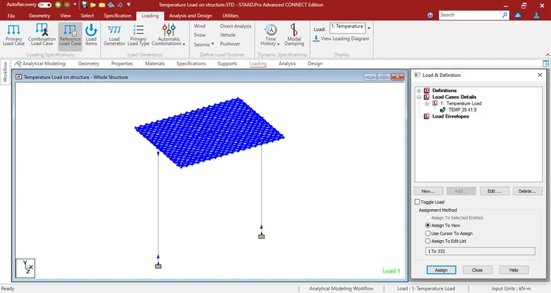
Step (11) :- Analysis of model.
- For analysis of the structure go to analysis and design option.
- In that click on run analyis option then analyis process will start.
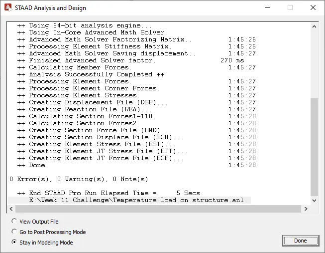
- After sucessfull analysis of the structure click on post processing mode to view the result.
Result :-
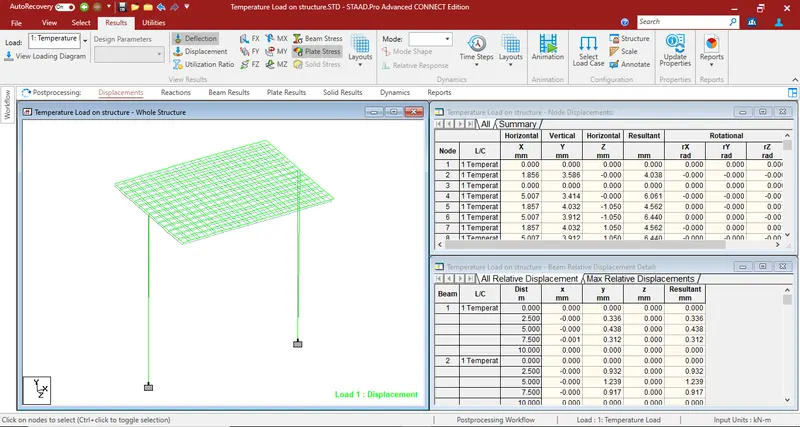
A) Bending Moment result
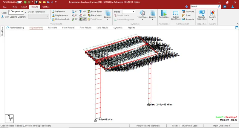
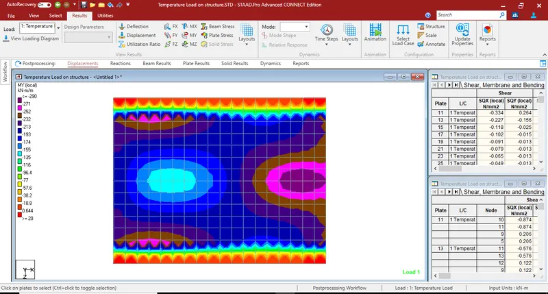
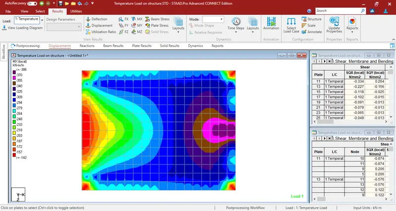
B) Plate stress in MY and MX local.