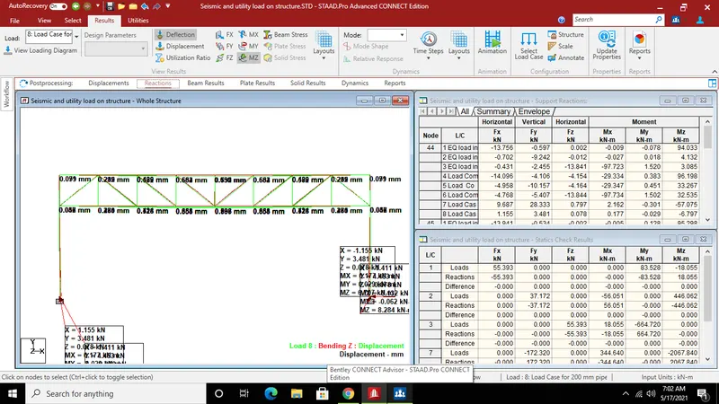
Week 6 Challenge
Aim :- To Create Steel truss bridge model and Applying seismic & pipe load on it and performing analysis using STAAD.pro software.
* Manual Calculation of pipe load *
Given -
Widht of bridge is 3 M
Lenght of bridge is 24 M
NB DI pipe 700 mm Dia
NB DI pipe 200 mm Dia
Assumption for model -
Height of the pier is 7 Meter ( Concrete)
Top and buttom chord is ISMB 250
Vertical and strut is ISMC 200
Diagonal and top lateral bracing in ISA 90x90x8
To Find -
Total pipe load acting om pier
For 700 mm dia pipe
= 338.2 kg/m
= 3.38 Kn/m
Area of pipe
=`pi/4 (0.7)^2`
=0.38 `m^2`
Live load on pipe
= Area x Unit Wt of water
= 0.38 x 10
= 3.8
Total load of pipe
= Self Wt + LL load
= 3.38 + 3.8
= 7.18 Kn/m
For 200 mm dia pipe
= 60.1 Kg/m
= 0.601 kg/m
Area of Pipe
= `pi/4(0.2)^2`
= 0.031 `m^2`
Live Load on pipe
= Area X Unit Wt of Water
= 0.03 X 10
= 0.3
Total Load of pipe
= Self Wt + LL load
= 0.031 + 0.3
= 0.331 kn/m
* Modeling and Analysis using STAAD.Pro *
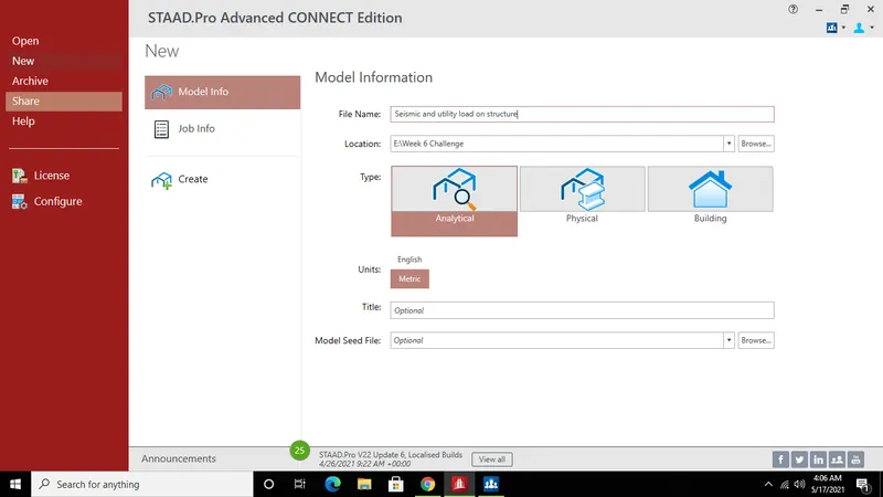
Step (1) :- Open a STAAD.pro software.
- Open a STAAD.pro software.
- Fill all detail about model in model information.
- Then click on the create to open the model.
Step (2) :- Create Floor beam of steel struss model.
- After opening STAAD.Pro software.
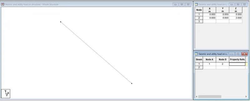
- Create the first node.
- Copy the node in global Z direction using translation repeat option.
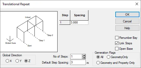
- Width of bridge is 3 meter which is given.
Step (3) :- Creating Bridge span.
- First Select the beam.
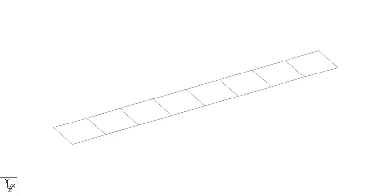
- Then Copy that beam in X direction using translation repeat option.
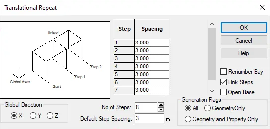
- No of step is 8 and spacing is 3 meter and also click on the link step to connect all the beam.
Step (4) :- Creating Top chord and vertical for truss bridge model.
- First select all the span.
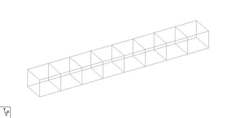
- And Copy the span in Y direction using translation repeatoption.
- Height of the bridge is 2.4 meter which is given in cross-section plan.
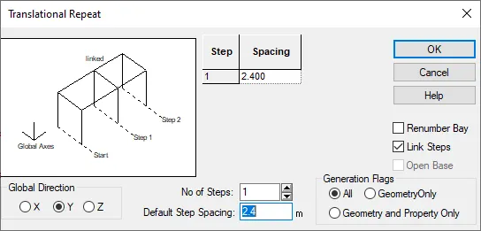
- No of step is one and spacing is 2.4 meter click on the link step to connect all the model.
Step (5) :- Creating Top lateral bracing and diagonal for bridge model.
- First go to geometry and select add beam option.
- Connect all the node using add beam option likewise in given plan.
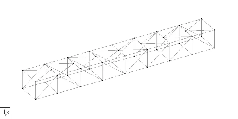
Step (6) :- Adding pier and assigning the support to it.
- Select end node of all four side of the.
- Copy selected node in Y direction using translation repeat option.
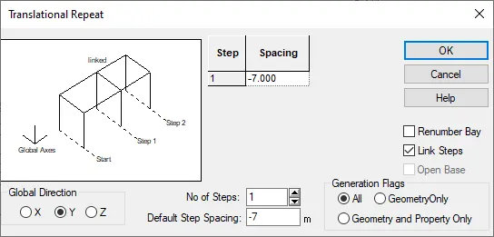
- Height of the pier is we assume 7 meter click ok to create.
- Now, assigning support to the pier.
- For that go to specification in this select fix support option. then click on add.
- Select the support and assign it to the pier.
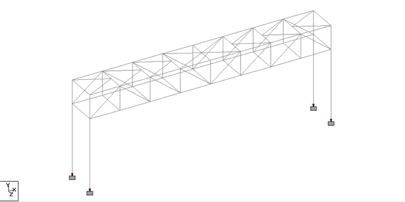
Step (7) :- Assigning property to the buttom and top chord component of the structure.
- First go to specification then in right side of the window this window will shown.
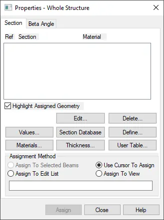
- In this window click on section Database then section profile table window will open.
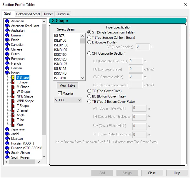
- Select indian option then click on S shape then select ISMB 250 property then click on add.
- After that select buttom and top chord component of the structure and assign this property to it
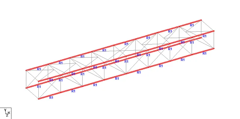
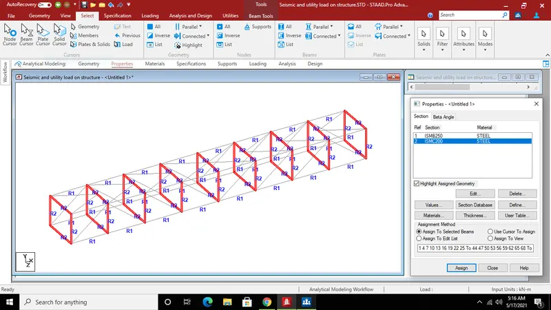
Step (8) :- Assigning property to Vertical and strut component of the structure.
- Repeat same procedur which is shown in step 6
- Go to channel section in the select ISMC 200 which we assume earlier.
- Select vertical and struct component of the structure and assign this property to it.
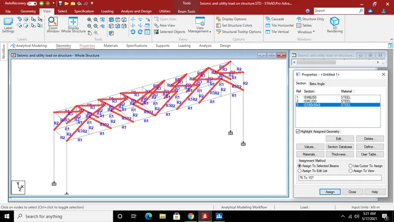
Step (9) :- Assigning property to top lateral bracing and diagonal component of the structure.
- Repeat same procedur which is shown in step 6
- Go to angal section in the select ISA 90x90x8 section which is our assemption.
- Select top lateral bracing and diagonal component of the structure and then assign this property to it.
Step (10) :- Assigning property to the pier.
- First go to specification in the select prismatic option then this window will open.
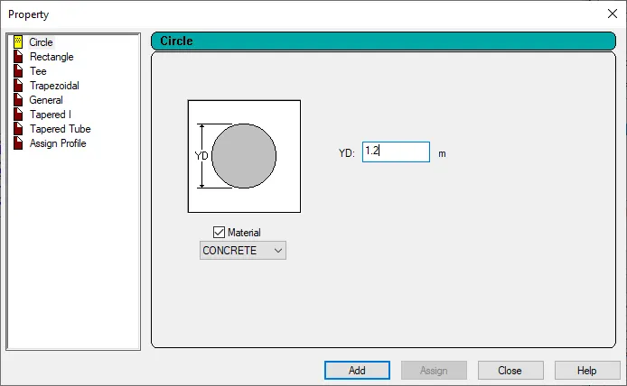
- Click on circle option and assume 1.2 meter diameter size of the pier and select the material as concrete and click on add.
- After select induidial all the pier and assign this property to it.
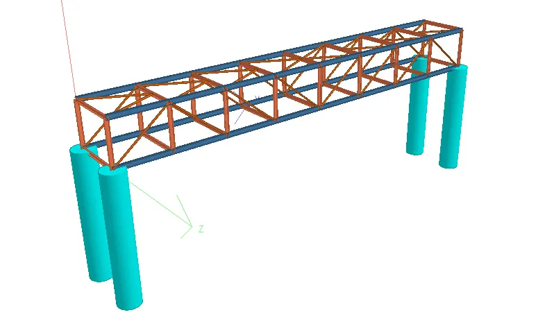
- Hence, all propety is assign.
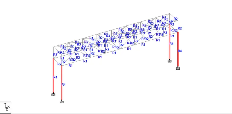
(3D Model)
Step (11) :- Applying Seismic load to the structure.
- Go to loading option in loading option this window will shown right side of the window.
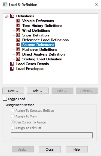
- In that window go to defination in that select seismic defination and click on add.
- Then Seismic defination window will open.
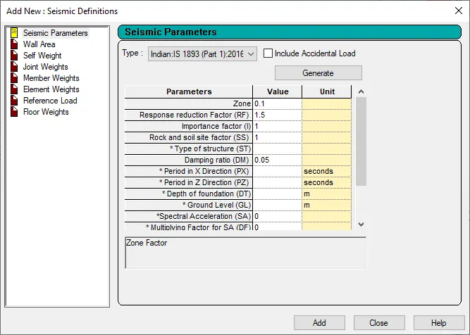
- First select IS 1893 (part 1):2016 indian code and then click on generate option and this window will open.
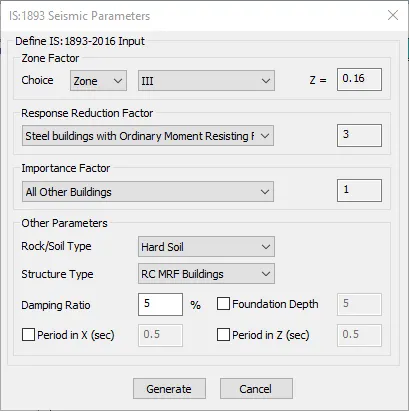
- Narmad river is flowing in zone III region so select zone III
- Then select response reduction factor as steel building with ordinary moment resistance.
- And Important factor as All other building.
- (The structure which we created is not important structure it is only use for pipe carying so select IF as all other building).
- Then click on generate button and add self weight also.
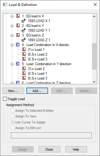
- After that select load case detail in load and difination window then click on add option .
- Create Load cases in all the direction (i.e X, Y , Z global)
- Select load case of X direction and click on add option then this window will open.
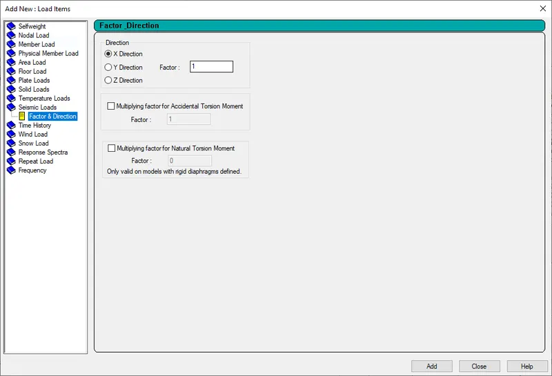
- In this window go to seismic load and select X direction and then click on add.
- Repeat this procedure in all the directiion individual Y & Z direction.
- Next is to define load combination for that structure.
- For that again select load case detail and click on add option then this window will open.
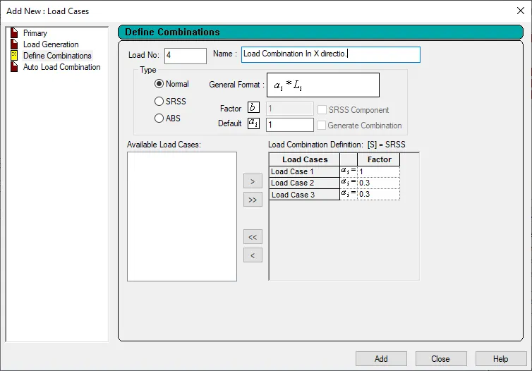
- In this window first go to define combination option then put the value in that
- Consider Factor 1 for X direction and 0.3 for other direction.
- Repeat this same procedure for different direction to define load combination.
Step (12) :- Applying pipe load on Structure.
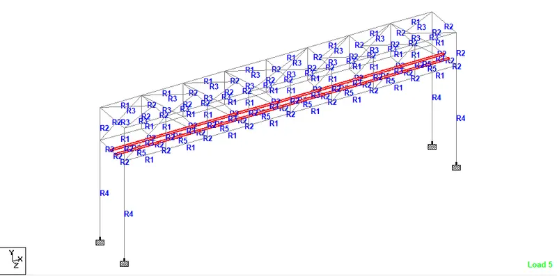
- First we need to create the beam for pipe.
- For that select all end node of Z direction which is parallel to X direction.
- Then copy them in - Z direction upto 1 meter by using translation repeat option.
- Again select copied node and again copy them in -Z direction uoto 0.64 meter.
- Connect all the node using add beam option for making beam.
- After that select both the beam and assign this ISMB 300 property to it (Assumption)
- Now Assigning pipe load on the beam.
- Fo that go to loading in right side load and difination window select load case and click on add option.
- Then create load case for 700 mm dia pipe.
- Again create another load case for 200 mm dia pipe.
- After that select load case for 700 mm pipe and click on add then this window will open.
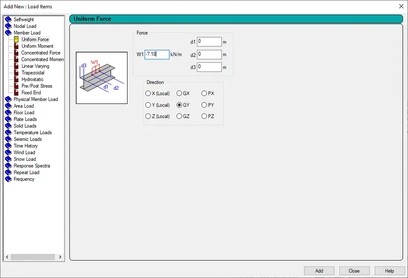
- In this Window select member load put UDl value 7.18 Kn/m for 700 mm dia pipe as we calclated manually above and click on add.
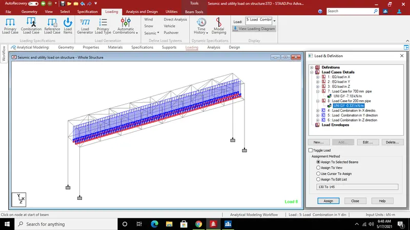
- Then Select the First beam we created earlier and assign this load on it
- Repeat this same procedure for 200 mm dia pipe and UDL value is 0.331 kn/m manually calculated above and assign this load to second beam.
- Hence, All load is assigned
Step (13) :- Analysis of Model
- After Applying load to the structure go to analysis and design option and click on run analysis.
- Then analysis process will start.
- After analysis process is done then click on postprocessing mode to view the result.
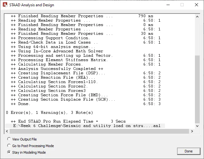
Result :-
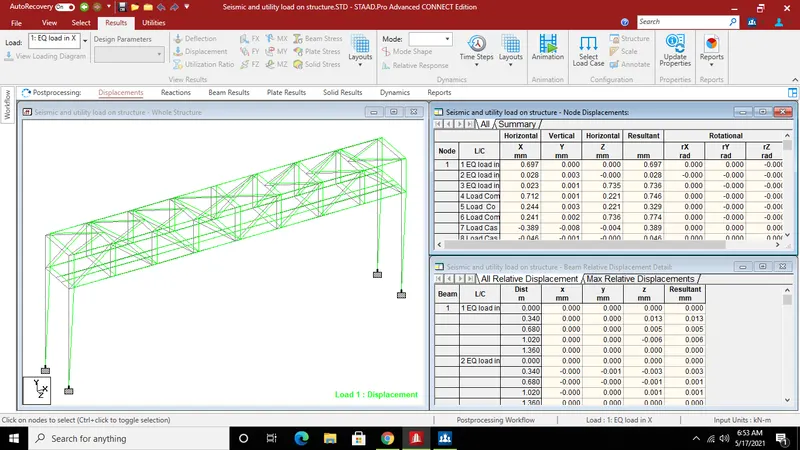
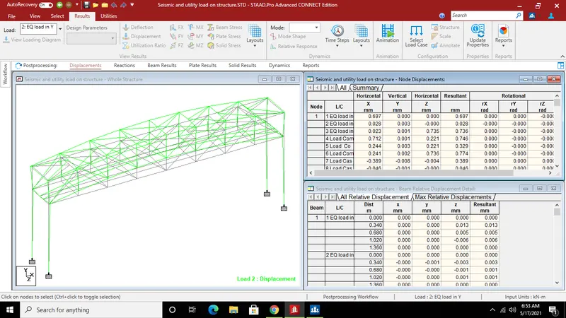
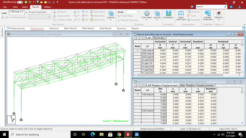
(1) Seismic Load result
a) Deflection in X direction
b) Deflection In Y direction.
c) Deflection in Z direction.
d) Reaction and bending moment diagram.
(2) Pipe load result
a) Deflection and bending moment diagram of NB DI 700 mm pipe
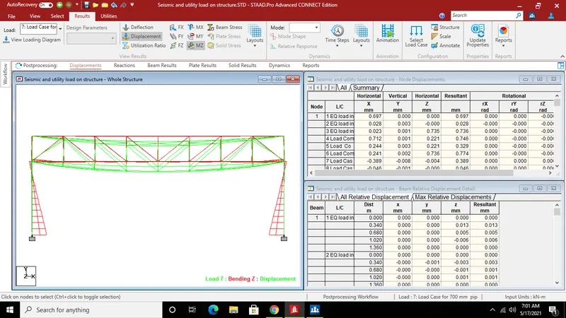
b) NB DI 200 mm pipe result.