Week 7 Challenge
Aim :- To Create 90 Meter Long spam Bridge Model and Applying Water Current Load On Pier as per IRC:6 and performing analysis using STAAD.Pro software.
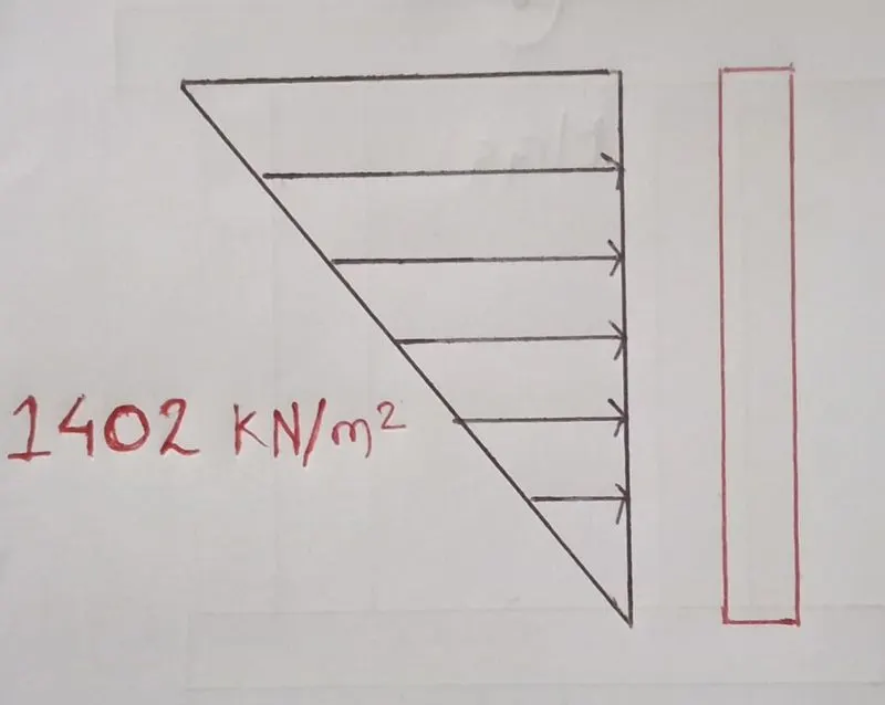
* Mannual Calculation of water current load acting on pier.
Given Data :-
- The high flood level is 2 m above the foundation level.
- The span of the bridge is 45m.
- The mean velocity of the river is 3 m/s.
Assumption :-
- We are assuming rectanguler pier so K factor as per IRC:6 is 1.50 .
To Find :-
- Maximum Velocity (V).
- Intensity Of pressure due to water current. in kg/`m^2` (P).
Solution :-
Calculation of maximum velocity, V
V = `sqrt 2`x Vmean
= `sqrt 2` x 3
= 4.24
Claculation of Water Current, P
P = 52 x K x `V^2`
= 52 x 1.50 X `4.24^2`
= 1402.25 KN/`m^2`
* Modeling and Analysis using STAAD.pro
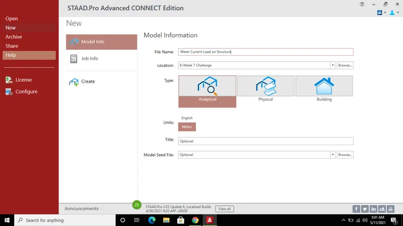
Step (1) :- Opening of STAAD.Pro Software.
- Open a STAAD.pro software.
- Fill all detail about model in model information.
- Then click on the create to open the model.
Step (2) :- Creating Crossbeam grid.
- After opening STAAD.Pro software.
- Create the first node.
- Copy the node in global Z direction using translation repeat option.
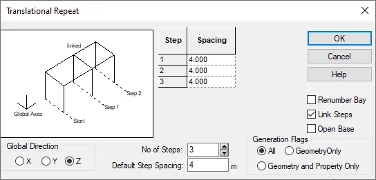
- No of step should be 3 and spacing should be 4 meter.
- Click on the link step to connect all the node.
- We are assuming 12 meter width of the bridge.
- 3 span of 4 metre width.
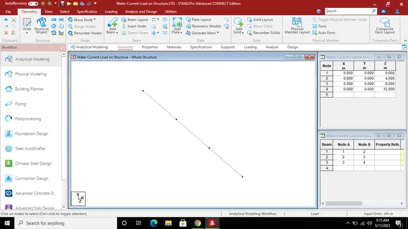
Step (3) :- Creating Main girder grid.
- For creating Main girder grid copy this grid in X direction using translation repeat option.
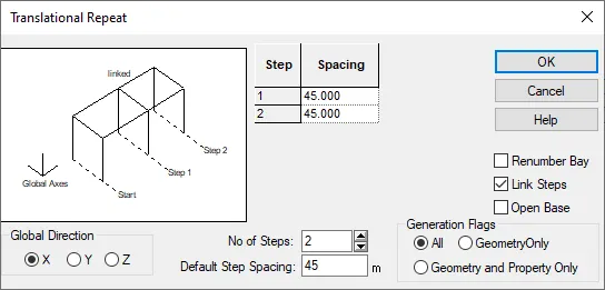
- 90 Meter long span is given in question.
- So no of step in 2 and spacing is 45 m.
- click on the link step to connect the node and then click on the ok button to create the grid.
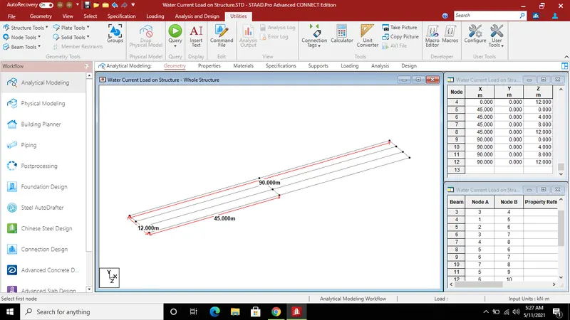
Step (4) :- Adding Pier to the Grid model.
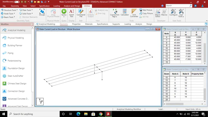
- We have to create the pier in center of the span in Global Y direction.
- Fo that select the span centerd both end node and copy this node in global Y direction using translation repeat option.
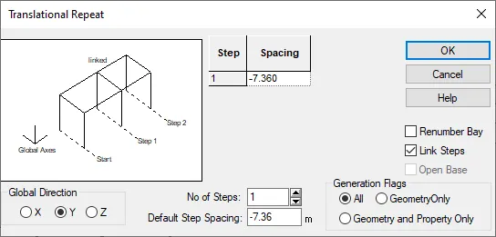
- No of step is 1 and spacing is 7.36 and click on link step to connect the 2 node and then click on OK to create the pier.
- In question high flood level is 2 m above the foundation level and Vertical clearence is given 5.36 M.
- So, 2+5.360 = 7.36 M.
- We have to provide the 7.36 metre height of pier in global Y direction.
Step (5) :- Creating abutment to both end of the bridge.
- Select the any one node of starting point of the bridge.
- Copy this node in Z direction using translation repeat option upto 0.5 meter spacing.
- And again select both the node and copy them in global Y direction using translation repeat option upto 0.5 meter spacing.
- After creating of node next step is to add plate on it.
- For that go to goementry in that select add plate opton and then connect all the node using add plate option.
- Hence one plate is created.
- Then select that plate using plate cursor option and copy that plate in global Z direction using translation repeat option.
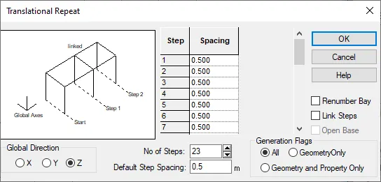
- No of Step we have to provide 23 and spacing is 0.5 in Z dirction.
- We assume 12 meter span of bridge so, 12/0.5 = 24 -1 = 23 no of step we have to provide.
- Then Click Ok to copy the plate in Z direction.
- Again select all the plate and copy them in Y direction using translation repeat option.
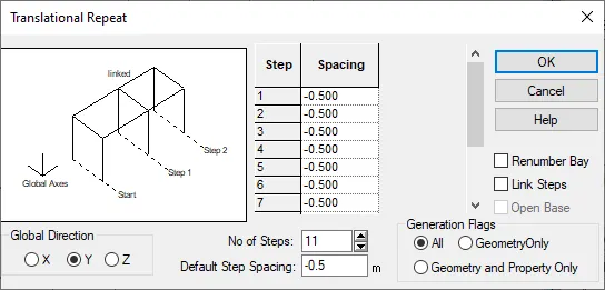
- No of step we have to provide 11 and spacing is 0.5 in Y direction.
- We assume 6 meter height of the abutment so, 6/0.5 = 12-1 = 11 no of step we have to privide.
- Then Click on Ok to copy all the plate in Y direction.
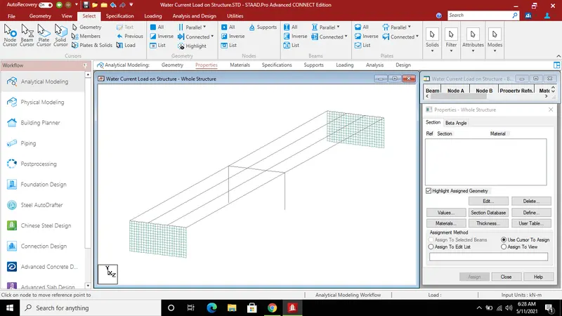
- Hence abutment is created.
- After Creation of Abutment again repeat this process in end side of the span to create the secound abutment.
Step (6) :- Creating raft foundation plate
- First select buttom node of the pier using node cuirsor then copy that node in X direction using translation repeat option upto 0.5 m.
- Again select both the node and copy them in Z direction using translation repeat option.
- Then add plate in it, for that go to geometry in that select add plate option then connect all the node using add plate option hence plate is created.
- Select that plate using plate cursior option then copy that plate in Z direction using translation repeat option.
- We assume 12 meter deck width so, no of step should be ( 12/0.5 )= (24-1) = 23 nos and spacing should be 0.5 meter.
- Again select all the plate and copy them in X direction using translation repeat option.
- No of step we consider 3 nos and spacing is 0.5 M.
- Again select this first plate and copy them in inverse X direction.
- No of step we consider 4 nos and spacing in -0.5 M.
- Width of the raft foundation is 3.5 meter.
- Select the top plate and copy them in inverse Z direction no of step we consider 2 nos and spacing is 0.5 m.
- Do same for buttom plate of raft foundation also. Lenght of raft foundation is 14 meter.
- Repeat the same procedure below the both abutment wall to create the foundation plate.
- Now apply foundation property to it.
- For that go to specification in that select foundation option then this window will open.
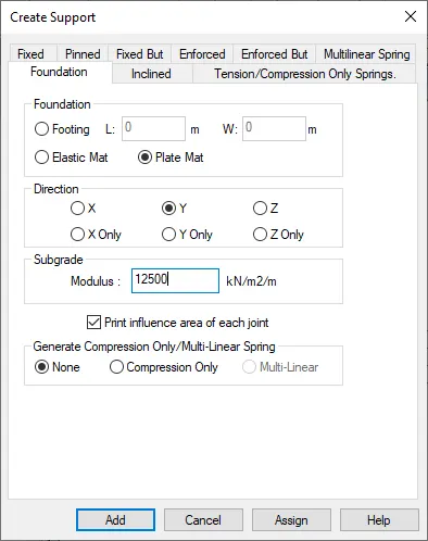
- Select foundation plate mat type and direction in Y assuming the sbc 12500 Kn/`m^2` then click on add.
- Select all foundation plate and assign this to foundation property to it.
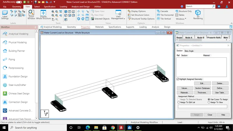 \
\
Step (7) :- Creating Deck plate on the top of bridge.
- Select first node above the foundation.
- Copy that node in X direction using translation repeat option upto 0.5 meter.
- Again select both the node and copy them in Z direction.
- Add the plate in that node for that go to geomety and select the add plate option then connect all the node using that.
- Hence one plate is created.
- Select that plate using plate coursor option and then copy it in the Z direction using translation repeat option.
- We consider 12 meter width of birdge so, No of step is 23 and spacing should be 0.5 meter.
- Again select all the pier and again copy them in X dirtection using translation repeat option.
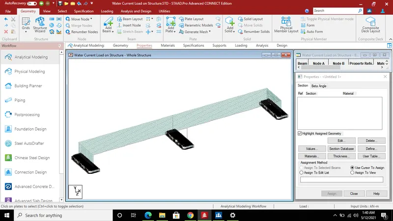
- 90 meter span in given so , no of step is 197 and spacing should be 0.5 meter.
- Hence deck is created.
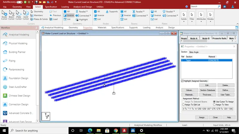
Step (8) :- Assigning property to Girder.
- For assigning property go to specification in that select prasmatic option then this window will open.
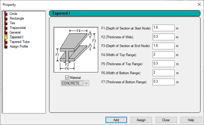
- Select tapperd I section and select concrete as material and put value as mention in above window then click on add.
- Then select all the girder which is parellel to X direction.
- Assign this property to it.
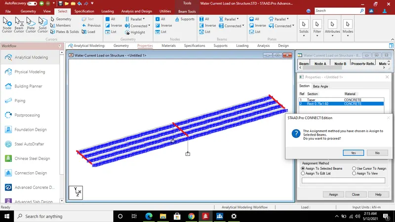
Step (9) :- Assigning property to crossbeam.
- For assigning property go to specification in that select prasmatic option.
- In that window select the rectangular option and assume the size of crossbeam 0.75 X 1.6 meter click on add.
- Then assign this property to it.
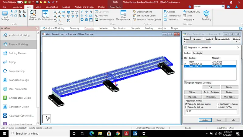
Step (10) :- Assigning property to pier.
- Assuming Size of pier is 1.2 M X 1.2 M.
- For that go to specification in that select prasmatic opton.
- Select rectangular and put size of the pier in it.
- Select the pier and assign this propeerty to it.
Step (11) :- Adding plate thickness to Abutment .
- Go to specification in thet select plate thickness option then this window will open.
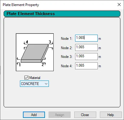
- We are taking plate thickness as 1.065 m which is given in the question.
- Then click on add button.
- Select all abutment plate and assign this property to both end side of the bridge.
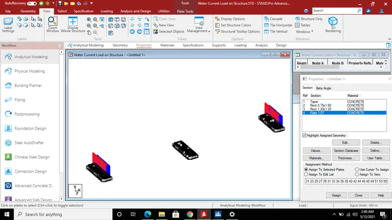
Step (12) :- Adding plate thickness to deckslab of the bridge.
- Repeat same procedure as mention in above step .
- Thikness we have to assume 0.350 m.
- Then Assign this property to deckslab of the bridge.
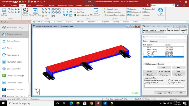
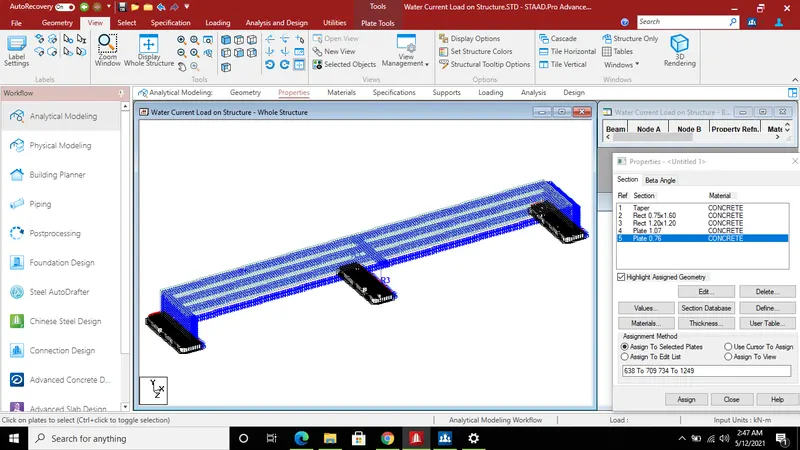
Step (13) :- Assigning plate thickness to raft foundation.
- Repeat same procedure as mention above.
- Thikness we have to provide 0.765 m which is given in question.
- Then Assign this property to both side of the abutment wall foundation plate.
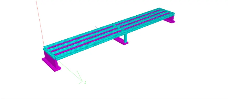
( 3D Model )
Step (14) :- Applying Water current load on structure.
- After assigning all propery to the structure.
- Next step is to apply loading on the structure.
- For that go to loading option the this dialog box will shown in right side of the window.
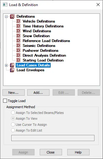
- In this dialog box click on the load cases detail then click on add option.
- And creater load case 1
- Select the load case 1 (Water current load) click on add button then window will open
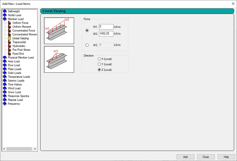
- In above window go to member load in that select Linear varing load and put value as mention in above window.
- We calculate water current load munnualy which is 1402.25 `m^2`.
- This value we have to put in above window as water current pressusre.
- After adding all value and selecting direction click on add option.
- Then Select the pier of structure and assign this water current load to it.
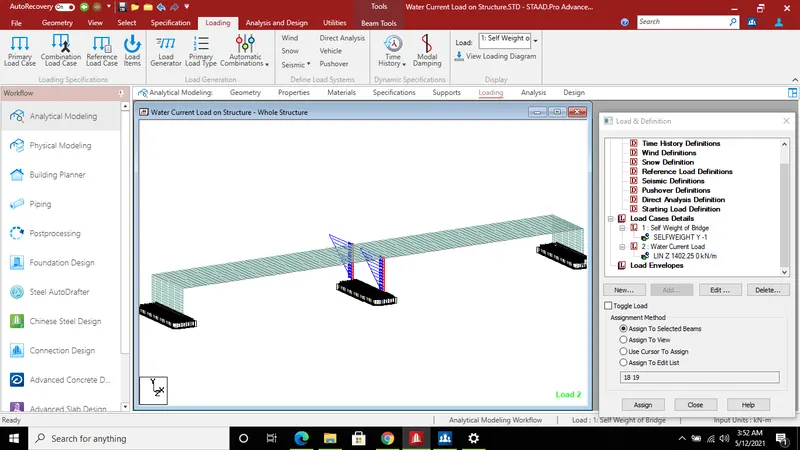
Step (15) :- Analysis of Model
- After Applying load to the structure go to analysis and design option and click on run analysis.
- Then analysis process will start.
- After analysis process is done then click on postprocessing mode to view the result
Note - Before starting analysis check for the plate connectivity, duplicate node or duplicat plate to verify where our structure which we have model is correct or not.
Results :-
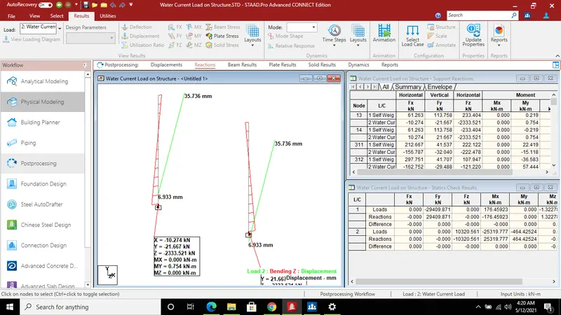
A) Reaction Result
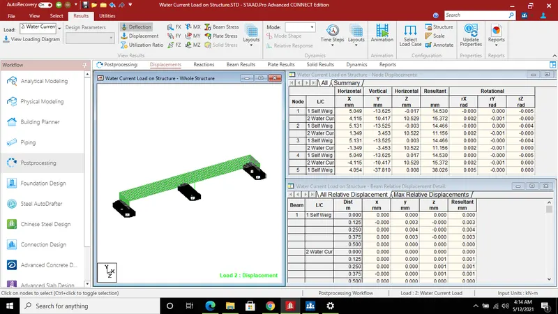
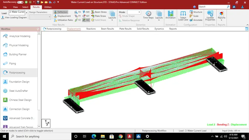
B) Deflection and Bending moment diagram of structure in Z direction.
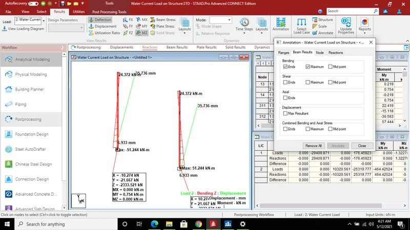
C) Pier Result
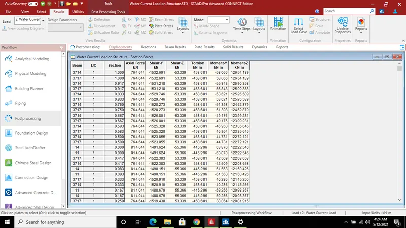
D) Section forces result
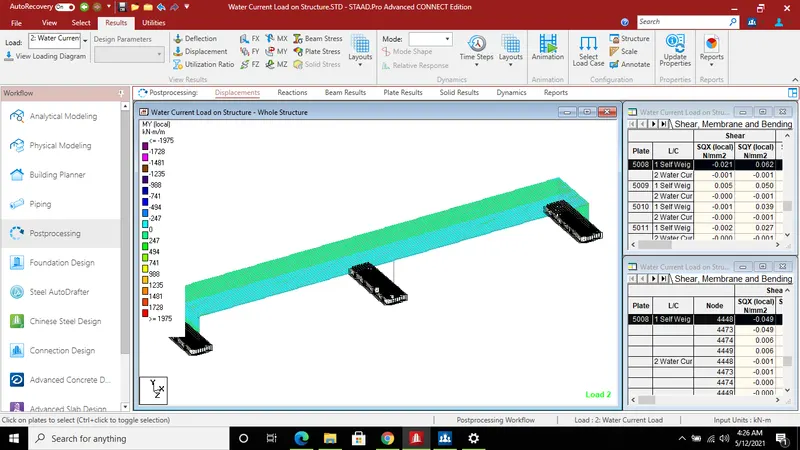
E) Pate stress in MY local