Week 3 Challenge
Question :-
1 ) How hydrology and geotechnical studies are used in fixing span and type of bridge.
Hydrology studies we have to do for fixing span is :-
- We have to collect data hydrological data from the site like ( Stream flow data, Observed high flood level, ordinary flood level, Flow condition)
- Hydrogical detail survey we have to do before construction.
- Site visit for actual observation.
- Hydrological analysis, the estimation of flood discharge.
- The calculation of flood patterns , flood level, & flood velocity.
- Bridge proposal including assesment of option.
- Frequency of submerge & duration of traffic obstruction.
- Scour assessment.
- Percentage obstruction to flow.
All the hydrology studies is refer from ( IRC 5 )
Geotechnical studies are :-
- Nature of soil we get from geotechnical report.
- Suitable depth for foundation.
- Bearing capacity of soil.
- Location of water below the ground.
- Topography of soil at site location.
- Frictional resistance of soil.
- Density of soil and other parameters.
Type of bridge :-
Base on structure
- Slab bridge
- beam bridge.
- Truss bridge.
- Arch bridge
- cable stayed / suspension bridge.
Base on Material
- Concrete bridge.
- Steel bridge.
- Stone bridge.
- PCC and RCC bridge.
Base on length.
- Culvert bridge ( Span < 6 M )
- Minor bridge ( 6 < span < 60 M )
- Major bridge ( spqan > 60 M )
- Long bridge ( Span > 120 M )
Base on function.
- Highway bridge.
- Railway bridge.
- Pedistrain bridge.
- Aquaduct / Viaduct.
- Road cum rail of pipeline bridge.
High level bridge / Submersible bridge.
span arrangement bridge ( Simply supported bridge, Cantilever bridge, Continous bridge ).
Determine the scour depth at the pier and abutment location having silt factor =3
Design discharge = 1000 cumecs
Linear waterway = 128 m
Assumption :-
4 pier ( 2 meter width )
Solution :-
Calculating Effective linear waterway
= Linear Waterway - 4 x 2
= 128 - 8
= 120 meter
Effective liner waterway is 120 meter.
Now,
Formula for Calculating Scour Depth
dsm=1.34 ( `Db^2` / Ksf )1/3
Where,
Db = The design discharge for foundation per meter width of effective waterway
Ksf = Silt factor for representative sample of bed material obtain upto the level of anticipation deepest scour
Determining the value of Db
Db = Design discharge / Effective liner waterway
= `1000/120`
= 8.33 m / s
The value of Design discharge Db is 8.33 m/s
As per clause 703.2.1 which is given in IRC:78 The value of Db may be determining by dividing thedesign discharge for foundation by lower of theoretical and actual effective linear waterway as given in IRC:5
Calculating the Score depth,
dsm = 1.34 `(8.33^2/3 )^frac{1}{3}`
= 3.81 Meter
Scour depth for foundation dsm is 3.81 Meter
Maximum Depth of scour for foundation design
Flood without seismic combination,
For Piers, = 2 X dsm
= 2 X 3.81
= 7.63 Meter.
For Abutment, = 1.27 X dsm
= 1.27 x 3.81
= 4.83 Meter.
Maximum depth of scour for pier is 7.63 M and for Abutment 4.83 M
1 b). what measures can be taken to avoid scour at bridge.
Following method are use to aviod scour at bridge.
1) Protection Work :-
- Stonepitching are done near the foundation to avoide from scour effect.
2) Providing flexible and rigid apron :-
- The rigid flooring should be provided under the bridge and it should extend for a distance of at least 3 m on upstream side and 5 m on down stream side of the bridge.
- Flexible apron 1 m thick comprising of loose stone bouiders (weighing not less than 40 kg) should be provided beyond the curtain walls for a minimum distance of 3 m on upstream side and 6 m on downstream side.
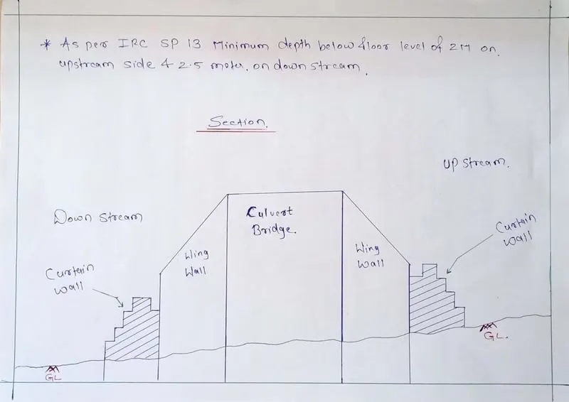
3) Cut - off Wall / Curtain Wall.
- The rigid flooring should be enclosed by curtain walls (tied to the wing walls) with a minimum depth below floor level of 2 m on upstream side and 2.5 m on downstream side. The curtain wall should be in cement concrete Ml 5 grade or brick/stone masonry in cement mortar 1:3. The rigid flooring should be continued over the top width of curtain walls.
4) Providing adequate depth of foundation.
- By calculating the scour we have to provide the sufficient depth to the foundation.
Draw sections of curtain wall in upstream and downstream of the bridge.
1 c). What is uplift and how it can affect the foundation. (loss of contact)
- Uplift pressure, which is also known as hydrostatic uplift, is an upward pressure applied to a structure that has the potential to raise it relative to its surroundings. It is the condition of greater pore water pressure than the overburden pressure of the structure.
- When a substructure is built inside an open excavation or temporary cofferdam, the base slab or raft foundation can be extended outside perimeter to increase resistance to uplift.
- Due to the fact that hydraulic uplift pressure acts in upward direction. Therefore, it reduces the downward weight of the structure and consequently it acts against the stability of structure.
Calculate the uplift in U trough of below section with height 3,4,5 meters. with water level on top of ramp wall level . What are different measures that can be taken to avoid uplift.
The uplift pressure is calculated as follow :-
The (hw) is taken from water table to buttom of U trought
Pu = `gamma w` X hw
= 10 X (3 + 4 + 5)
= 120 kN/`m^2`
Total uplift pressure acting on U trough is 120 kN/`m^2`.
2.5 is the factor of sefty to consider for Uplift.
Following are the measure that can be taken to avoid uplift :-
1) Toeing in the foundation into the surrounding ground.
- When a substructure is built inside an open excavation or temporary cofferdam, the base slab or raft foundation can be extended outside perimeter to increase resistance to uplift.
- The weight of backfill material on the tied-in foundation increase the weight of the structure against uplift pressure. This method is not feasible where a diaphragm or secant pile wall is used as a permanent retaining structure.
2) Increase in self wt. of structure.
- The self-weight of the bridge can be increased by increasing the size of structural members. sometime, the dead weight of the low-rise podium in a high-rise complex is increased by incorporating a rooftop garden with a thick soil fill.
3) Ground anchor
- Pre-stressed anchors can be used as a temporary measure to counteract uplift forces. Permanent application of ground anchors is limited by concerns about their long-term performance with respect to corrosion.
4) Piling Method
- The piling method is the most effective method to resist Uplift pressure. Various types of piles are available to be used for countering uplift pressure based on soil condition and their necessity on site.
- For instance, end bearing pile, friction pile, un-reamed pile, sheet pile, tension pile, and compaction pile. Table 1 presents different types of piles used to contain uplift pressure based on soil conditions.