Week 9 Challenge
Aim :- Calculate the wave load on the bridge superstructure and perform analysis using STAAD.pro software.
Manuall Calculation,
Given,
- The maximum crest elevation for the wave = 3 M
- Storm elevation = 8.5 M
- I girder size, * Height = 1.7 M * Flange width = 2.5 M * Thickness = 0.5 M
- Span of the bridge = 12 M
- Width of deck slab = 9 M
- Thickness of deck slab = 2 M
- Constant r = 5
- Cva = 3
- Cr = 0.4
Calculation,
Vertical Force Horizontal Force
Fv = `gamma` x (`Delta`Zv) X Av Fh = `gamma` X (`Delta`Zh) X Ah
= 10 X 2.8 X 108 = 10 X 1.9 x 26.4
= 3024 kN = 501.6 kN
`**`(Fv)max = Cva-v Fv
= 3 X 3024
= 9072 kN
Vertical Wave Load = (Fv) max / Av
= 9072 / 108
= 84 kN
`**`(Fh)max = [1+Cr(N-1)]Cva-h Ah
= [1+0.4(3-1)]x3x501.6
= 2708.64 kN
Horizontal Wave Load = (Fh)max / Ah
= 2708.64 / 24
= 112.68 kN
Analysis using STAAD.pro software,
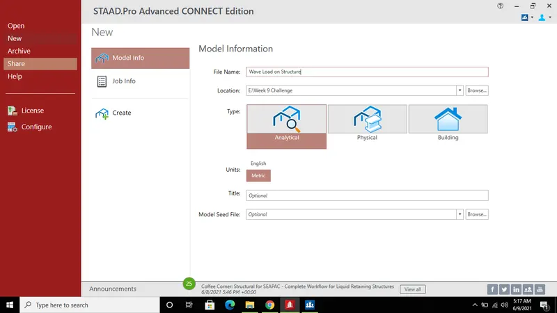
Step (1) :- Open a STAAD.pro Software.
- Open STAAD.pro software and Fill model information regarding structure.
- Then Click on create to open a model.
Step (2) :- Create Girder in model.
- Create first node using cordinate.
- Then Select that node and copy it in X direction using Translational repet option upto 12 meter.
- Connect both the node using Add beam option i.e one girder is created.
- Then select that girder and copy them in Z direction using translational repeat option.
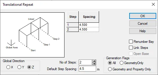
- In translational repeat option, No of step = 2 and spacing should be 4.5 meter then click on Ok to copy.
- Hence all gider is created.
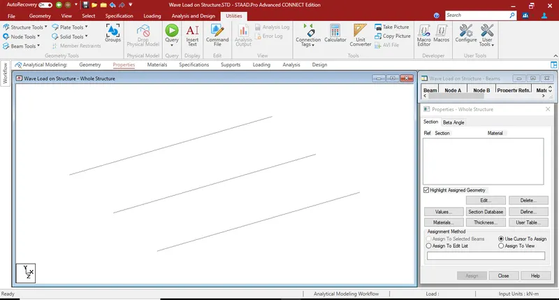
Step (3) :- Creating Crossbeam in model.
- For creating crossbeam first go to geometry in that select add beam option.
- Then connect all the node which is parallel to Z direction by using add beam option.
- Hence crossbeam is created.
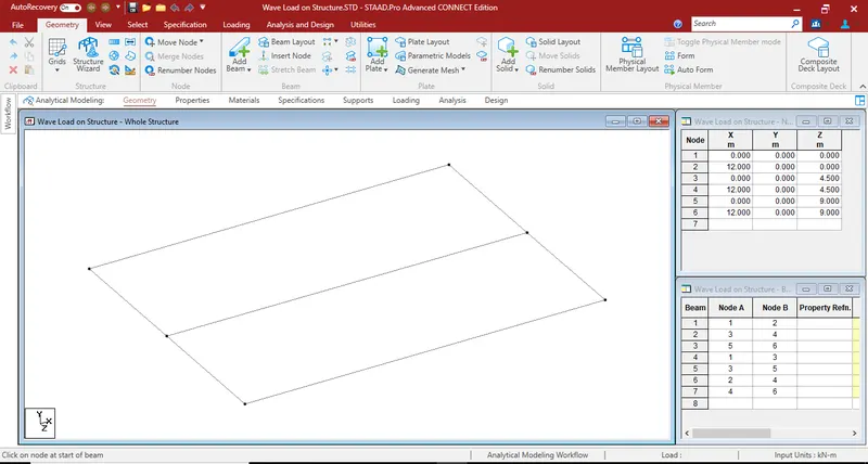
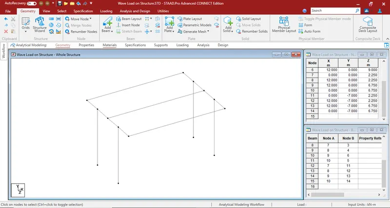
Step (4) :- Creating piers
- First we need to insert node in center of crossbeam to make a pier.
- For that go to geometry option then select insert node in beam menu after that courser will change.
- Select any crossbeam by using this cursor then this window will open.
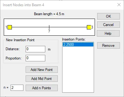
- In this window select add mid point then click on ok button, then node will be inserted at mid point of the crossbeam.
- Repeat this same procedure for remaing crossbeam.
- After that select all the node which we created, copy them in Y direction using translational repeat option.
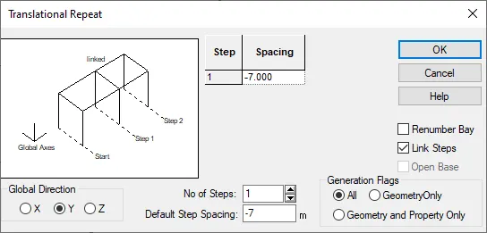
- Select global direction as Y and No of steps is 1 , and spacing should be -7 meter ( :. height of pier is given in que is 7 meter and ' - ' sign for inverse direction) also select link steps option to connect all the node.
- After that click on Ok to create a piers.
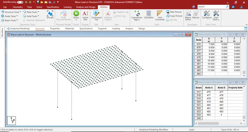
Step (5) :- Creating deckslab in model.
- Select the first node.
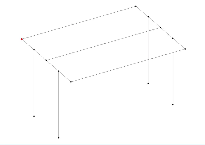
- Then Copy it in X direction upto 0.5 metre using translational repeat option.
- Again select both the node and copy them in Z direction upto 0.5 meter using translational repeat option.
- Adding plate to created node for that go to geometry then select add plate option.
- And connect all four node using add plate option (:. one plate is created).
- After that select that plate using plate cursor and copy them in X direction using translational repeat option.
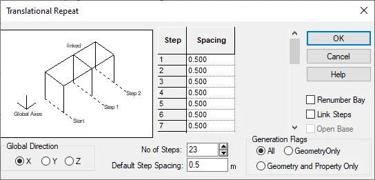
- In translational repeat Select global direction as X and spacing should be 0.5 meter.
- No of should be 23 (:. 12/0.5= 24, 24-1 = '23') click on ok to create.
- Again select all the plate which is parallel to X direction and copy them in Z direction using translational repeat option.
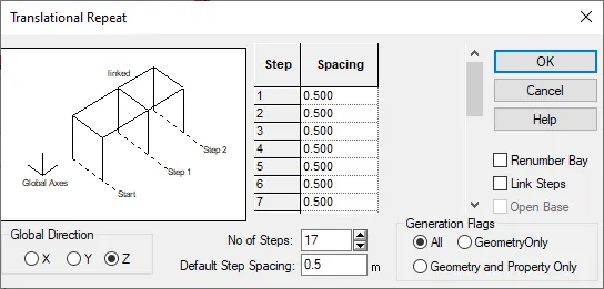
- Select direction as Z and spacing is 0.5 meter.
- No of steps is 17 (:. 9/0.5= 18, 18-1= '17') click on ok to create.
- Hence deckslab is created.
Step (6) :- Assigning support to the piers.
- For that go to specification then click on fixed support option.
- Create support window will open in this window also click on add button.
- Then support - whole structure window will shown.
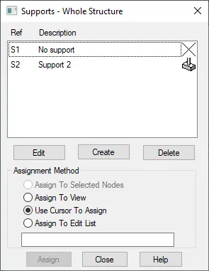
- In above window click on support 2 option then select buttom node of all the piers.
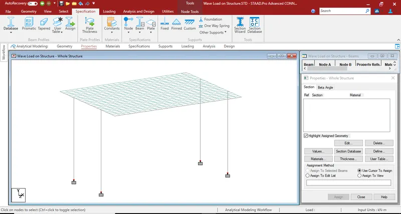
- Then select assign to selected nodes and then click on assign button.
- Support will be generated under all the piers.
Step (7) :- Adding property to the piers.
- Go to specification then click on prismatic option then property window will open.
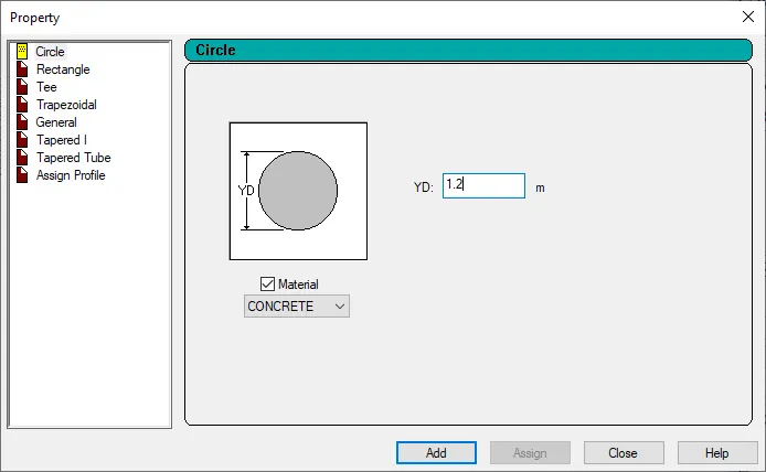
- In above window select circle then fill YD as 1.2 meter dia of circle (Assumption) then click on add option.
- After that select all the piers using beam cursor and assign this property to it.
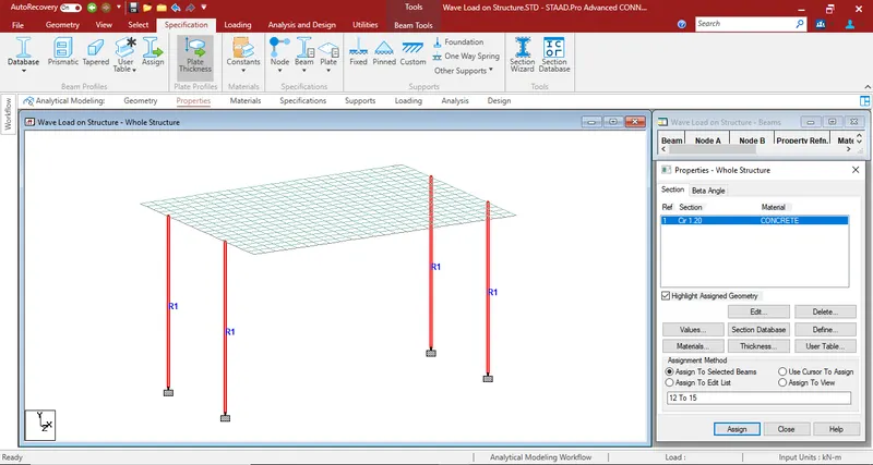
Step (8) :- Adding property to the girder.
- Go to specification then click on prismatic option then property window will open.
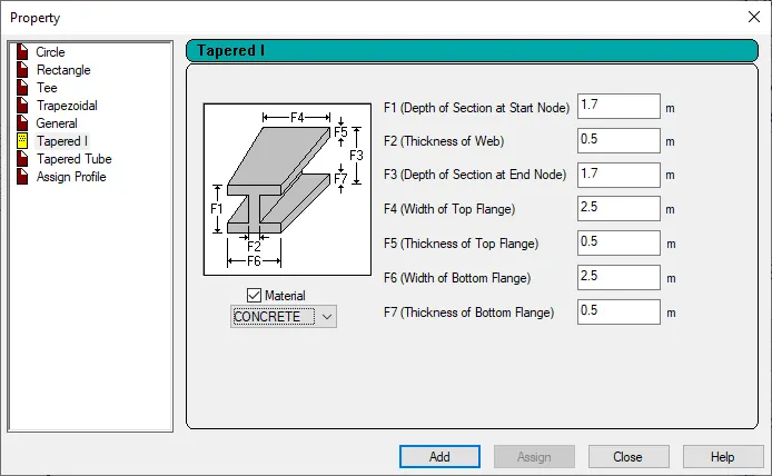
- In above window select Tapered I section and insert the size of girder which is given in question then click on ok.
- After that select the all the girder and assign this property to it.
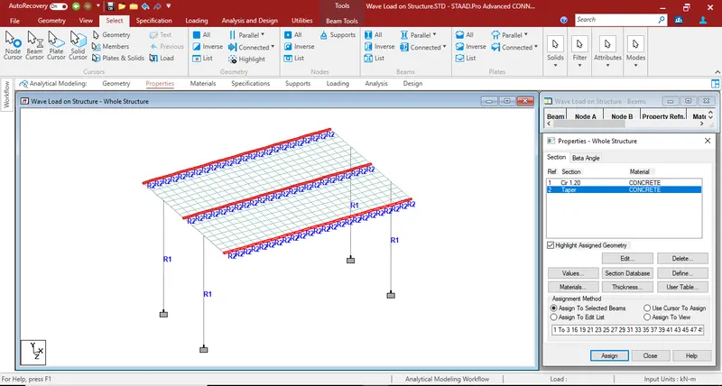
Step (9) :- Adding property to the crossbeam.
- Repeat same procedure as mention in step 8
- In property window select rectangle and assume size of crossbeam as YD as 1.7 and ZD as 0.75 meter.
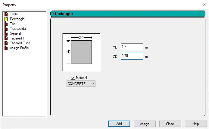
- Property is assign to crossbeam.
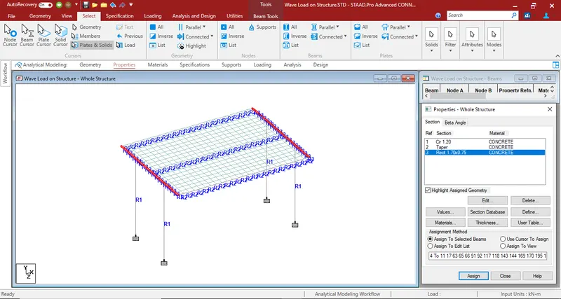
Step (10) :- Adding thickness to deckslab.
- Go to specification then click on plate thickness then plate element property window will open.
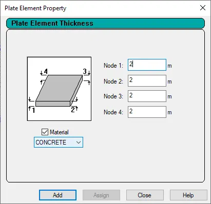
- Put 2 meter value of plate thickness as given in question and then click on add button.
- Then select all the deckslab plate using plate cursor option and assign this plate thickness property to it.
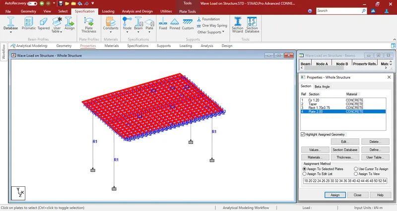
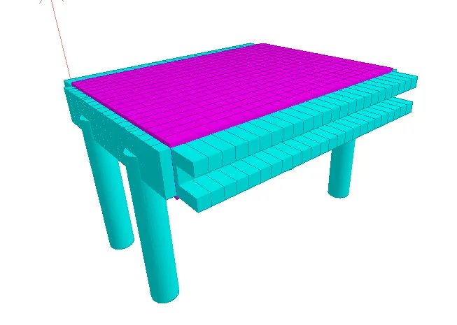
(3D Model)
Step (11) :- Assigning wave load on structure.
- First go to loading menu then in right side of the window this window will shown.
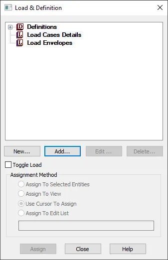
- In above window select load cases detail then click on add and then create one load case as 'wave load'.
- Then select that load case which we created again click on add button after that Add new: Load item window will open.
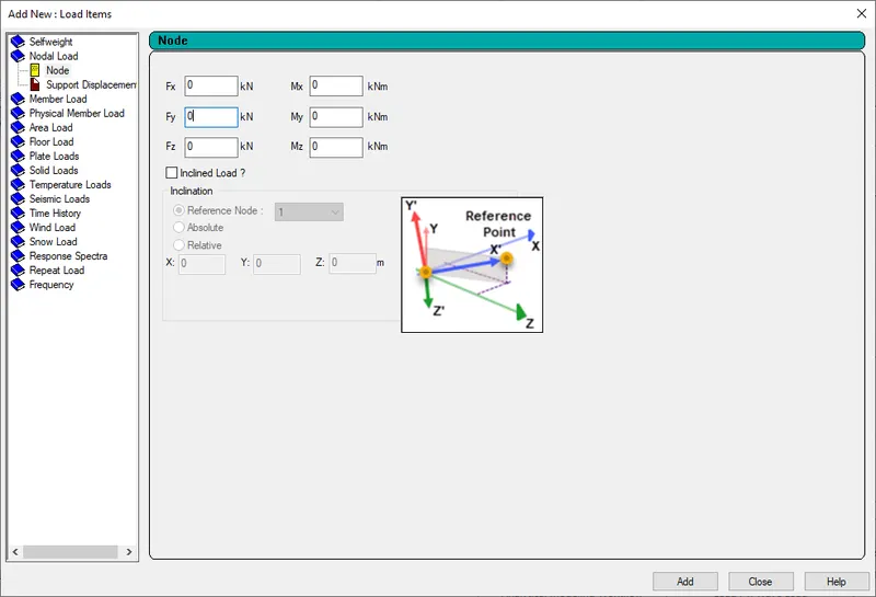
- In above window click on nodal load then select node option.
- After that put value of Fz as 112.68 kN in above window then click on add.
- After that again put value of Fy as 84 kN in that window, all value we calculated above mannually.
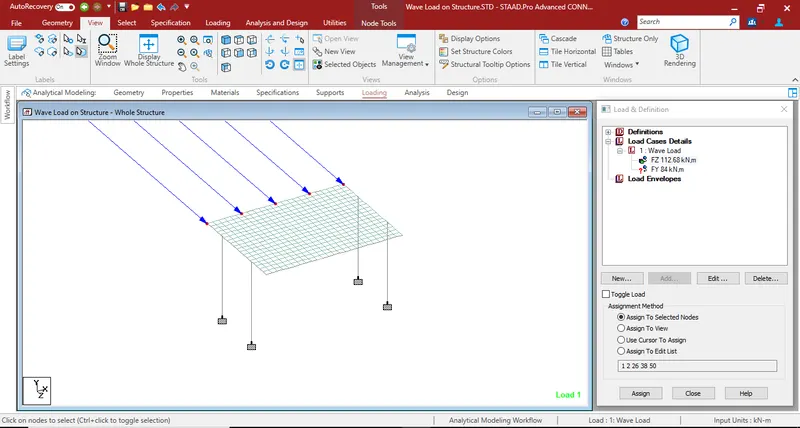
- Two load will be geneated.
- Then select Fz load and assign it to the selected node.
- Again select the second load Fy and assign to the center node of the bridge.
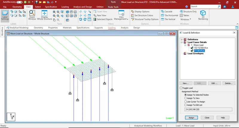
- Hence all loads is assigned.
Step (12) :- Analysis of structure.
- First go to analysis and design menu in that click on run analysis option.
- Then analyis process will start.
- After process is over this window will open.
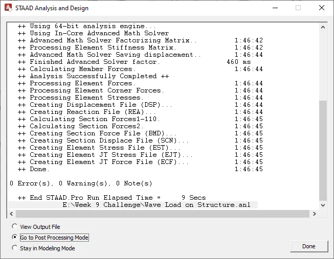
- In above window select post processing mode option and then click on done button to view the result.
Results:-
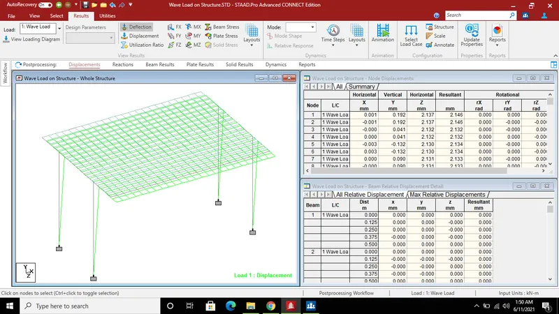
A) Bending moment result.
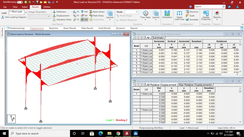
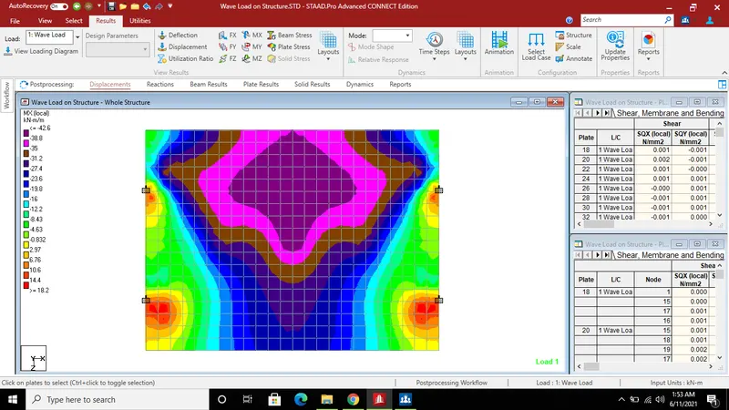
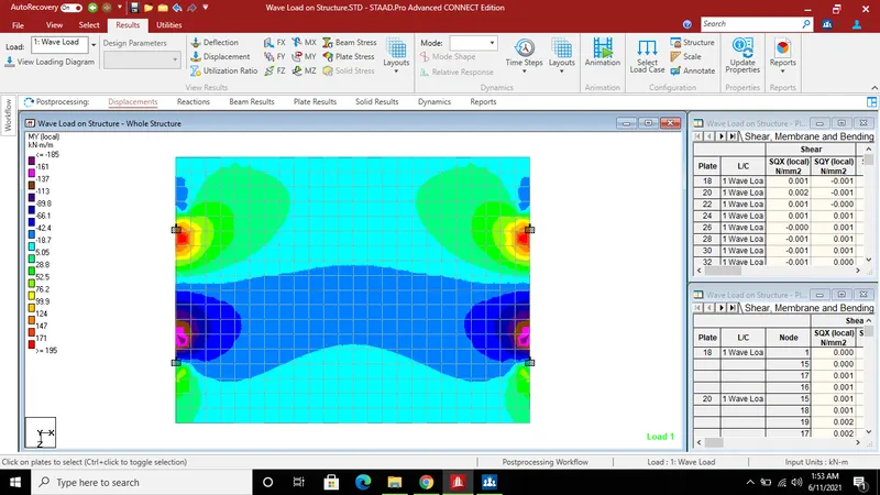
B) Plate result Mx And MY.