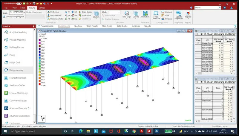
Project 2
Aim :- To Create Bridge Structure and Applying water current forces ,centrifugal forces, wave forces, snow loads, temperature loads, Barge Impact load on it and Perform analysis using STADD.Pro Software.
Proedure -->
Step (1) :- Creating Model and assigning property to it.
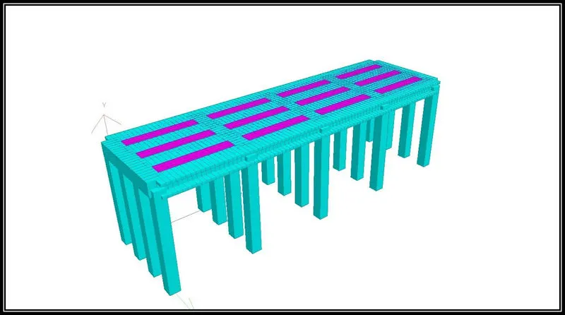
First Create a model in STAAD.Pro using Translational repeat option.
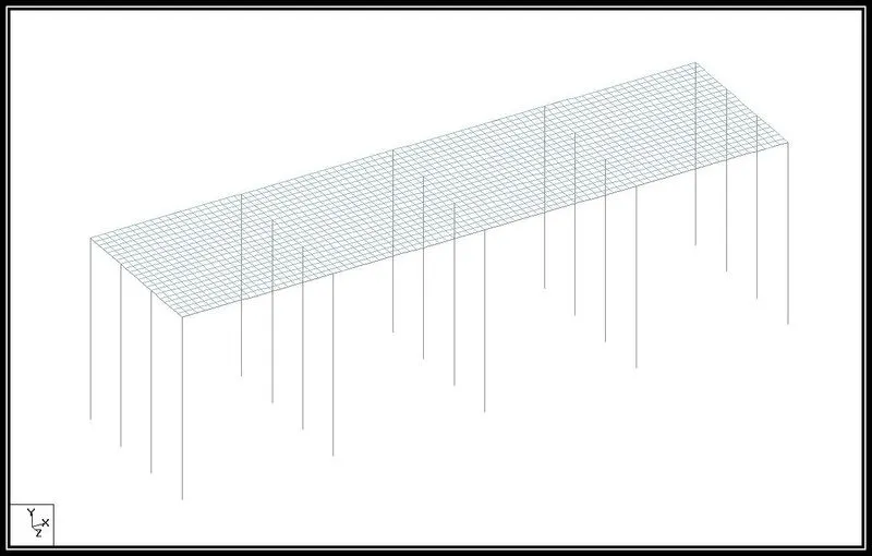
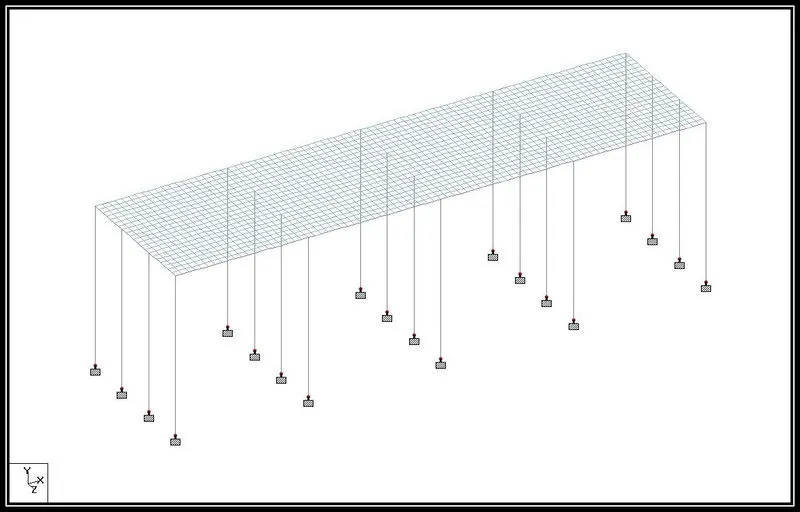
Now We need to assign the support to the pier.
For that following are the steps.
- First Go to Specification --> Fixed --> Support 2 --> Select all buttom node of the structure --> Assign to selected node --> Assign --> Yes
Assigning Property to each element.
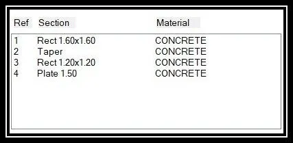
For Assigning beam element property
- Specification --> Prismatic --> In property window select suitable Property --> Put size of Property --> Select property --> Select Element --> Assign to selected beam --> Assign.
For Assigning Plate element property
- Specification --> Plate Thickness --> Size of the plate --> Add --> Select plate property --> Select plate property and then select plate element --> Assign to selected plate --> Assign.
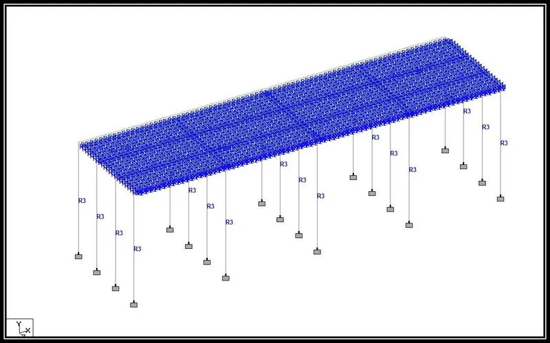
3D Model
Step (2) :- Adding and Assigning Loads to the structure.
1) Water Current Load.
Given Data --
The mean velocity of the river is 2.5 m/s.
The high flood level is 4 m.
For Calculation Of Water Current Load formula is given in IRC 6 which is P=52K`V^2`
Where,
P = Intensity Of pressure due to water current, in kg/`m^2`
V = The veloecity of the current at the point where the pressure intensity is being calculated, in meter per second and
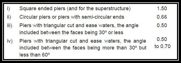
K = A constant having the following value for different shapes of piers illustrated .
We Consider the rectangular pier so value of K is 1.50 as given in below table.
Solution,
The height of pier subjected to water current H = 4 Meter
MAximum Velocit, V = `sqrt 2` X Vmean
= `sqrt 2` X 2.5
= 3.54
Water Current, P = 52 X K X `V^2`
= 52 X 1.50 x `3.54^2`
= 977.46 kg/`m^2`
We need to convert the value of P in Kilonewton.
Total Water Current Load acting on pier is 9.58 kN/m
Assigning Load on structure by using staad.pro software
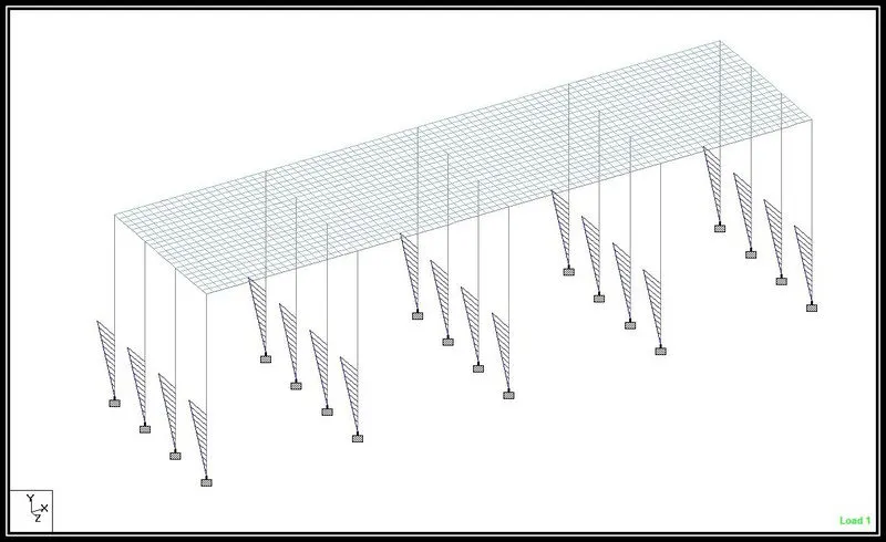
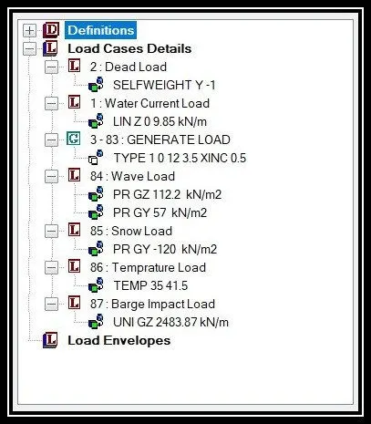
- Go to Loading --> Load & Defination --> Load Cases Detail --> Case 1 as Water Current Load --> Add
- Water Current Load --> Add --> Member Load --> Linear Variying --> W1 = 0, W2 = 9.85 --> Direction Z (local) --> Add --> Select pier then select Load -->Assign to selected beam --> Assign.
2) Centrifugal Load.
Given Data --
The design speed of the vehicles is 50 km/hr.
The bridge is subjected to a live load of Class 70R tracked vehicle.
Radius of curvature in the bridge is 2 m.
Centifugal force (C) = `frac{WV^2}{127R)`
Where,
C = Centrifugal force acting normally to the traffic (1) at the point of action of the wheel loads or (2) uniformly distributed over every metre length on which a uniformly distributed load acts, in tonnes.
W = Live load (1) in case of wheel loads, each wheel load being considered as acting over the ground contact length specified in Clause 204, in tonnes, and (2) in case of a uniformly distributed live load, in tonnes per linear metre
V = The design speed of the vehicles using the bridge in km per hour, and.
R = Radius of Curvature.
Solution,
Centrifugal Force C = `frac{700 X (50)^2}{127 X 2}`
= 6889.76 kN
Centrifugal Load acting on structure is 6889.76 kN.
Applying Load on structure using software
- Loading --> Load & Defination --> Definitions --> Vehical Defination --> Add --> Adding Calculated value --> Add
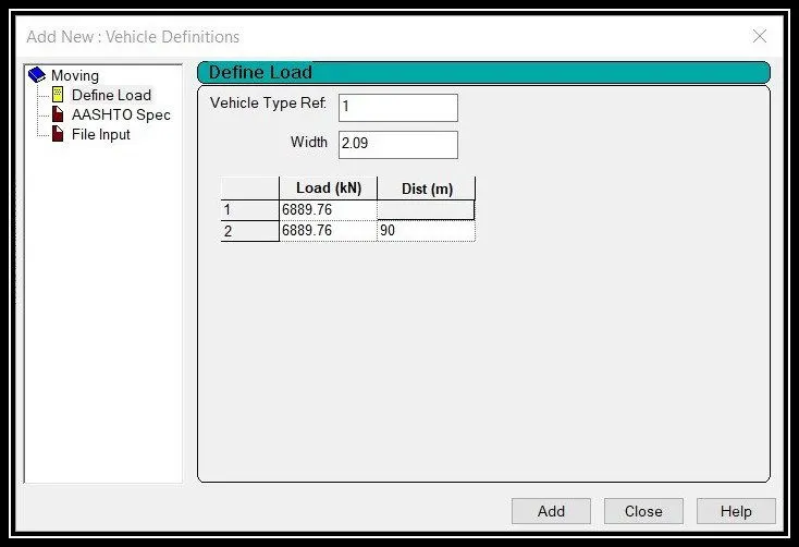
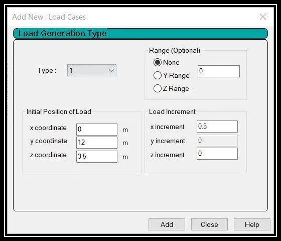
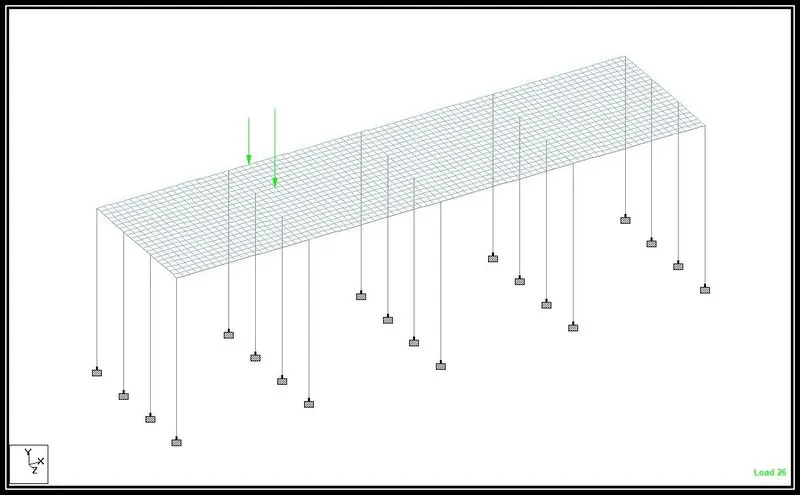
- Load & Defination --> Load Case Details --> Load Generation --> No of load to be generated (81 Nos) --> Add
- GENERATED LOAD --> Add --> Cordinates --> Add.
3) Wave Load
Given Data-
The maximum crest elevation for the wave is 3 m.
Constant r as 5.
Assume Cva as 3 & Cr as 0.4.
The Storm elevation is 8.5 m.
Each I Girder is 1.6 m height with a top and bottom flange width of 2 m.
We have to do calculation for wave load from IS 4651 Code
All the value we have to consider from this code.
Solution,
1. Fv = `gamma` X `Delta zv` X Av
= 10 X 1.9 X 420
= 7980 kN
2. Fh = `gamma` X `Delta zh` X Ah
= 10 X 1.7 X 104
= 1768 kN.
`**` Fv max = Cva-v Fv
= 3 X 7980
= 23940 kN
= `frac{(Fvmax)}{Av}`
= `frac{23940}{420}`
= 57 kN
`**` Fhmax = [ 1 + Cr (N-1) ] Cva-h X Ah
= [ 1 + 0.4 ( 4 - 1)] 3 X 1768
= 11668.8 kN
= `frac{Fhmax}{Ah}`
= `frac{11668.8}{104}`
= 112.2 kN
Total Wave Load acting on structure is Fv max = 57 kN & Fh max = 112.2 kN.
Assigning Load on structure model in staad.pro
- Loading --> Load & Defination --> Load Case Details --> Add --> Load case as ( Wave load) --> Add.
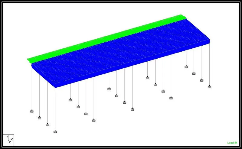
- (For Ah) Wave Load Case --> Add --> Plate load --> Pressure on full plate --> W1 = 112.2 kN direction as GX --> Add --> Select Load --> Assign to selected plate --> Assign.
- (For Av) Wave Load Case --> Add --> Plate load --> Pressure on full plate --> W1 = 57 kN direction as GY --> Add --> Select Load --> Assign to selected plate --> Assign.
4) Snow Load
Given Data -
The depth of accumulation of snow is 1.250 M.
The deck of bridge is flat with B <30 degree.
Assumption.
We assume settled snow so densiy of snow is 3 kN/`m^3`
Solution,
Snow Load (So)
S0 = Density Of Snow X Depth of Snow X Length of bridge
= 3 X 1.250 X 40
= 150 kN/m
Shape Of coefficient from IS 875 part 4
For angle `beta` < 30 degree , `mu` = 0.8
So,
Design Snow Load
S = `mu` X S0
= 0.8 X 150
= 120 kN/m
Snow Laod acting on the deck is 120 kN/m
Assigning Load on deck using staad pro
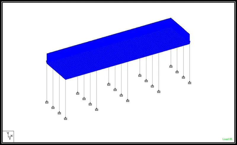
- Loading --> Load Case Detail --> Load Case as ( Snow Load) --> Add.
- Case (Snow Load) --> Add --> Plate Load --> Pressure on Full Plate --> W1 = -120 direction as GY --> Add --> Select load then select plate --> Assign to selected plate --> Assign.
5) Temperature Load
Assumption Data -
City we as assuming Delhi
Grade of concrete is M 40 grade.
1) Maximum temperature in the location as per IRC 6
Isotherm at the Location = 47.5 degree
2) Minimum temperature in the loaction as per IRC 6
Isotherm at the loacation = -2.5 degree.
`**` Effective temperature dfference
`Delta T` = `frac{47.5 - (-2.5)}{2} + 10`
= 25 + 10
= 35 degree.
`**` Stress due to tempereture = `alpha` X `Delta T` X E
Where,
`alpha` is coefficient of thermal expansion is reinfoeced concrete is taken as 11.27 X `10^-6` degree per centrigrade.
`Delta T` is Effective temperature difference.
E is Modulus of elasticity of material
= 11.27 X `10^-6` X 35 X 5000 `(40)^frac{1}{2}`
= 12.47 kN/`m^3`
`**` Maximum permissible stress
= `(2/3)` X 0.7 X `sqrt fck`
= `2/3`X 0.7 X `(40)^frac{1}{2}`
= 2.95 kN/`m^2`
Hence,
The stress are restricted to 3 kN/`m^2`
- Maximum temperature = 47.5 degree
- Minimum temperature = -2.5 degree.
Positive temperature difference
- Temperature at top = 47.5 degree
- Temperature at buttom = `(2.1/17.8)` X 47.5
= 5.60 degree.
Temperature at top is 47.5 degree and buttom temperature is 5.60 degree.
Assigning Load at software
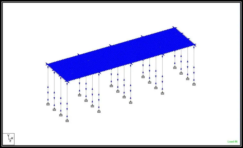
- Loading --> Load Case detail --> Add -->Case as ( Temperature Load) --> Add.
- Temperature Load --> Add --> Temperature Load --> Temperature --> Temperature change for axial elogation = 35 , Temperature difference from top to buttom = 41.5, --> Add
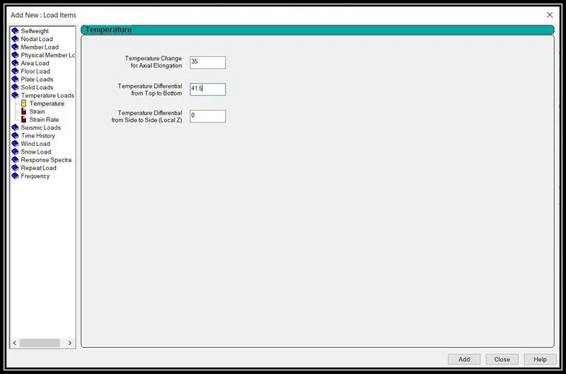
- Select Temperature load --> Assign to view --> Assign.
6) Barge Impact Load.
Given Data -
The Dead weight tonnage of Panamax vessel is 25000 DWT (W).
Assumption,
Velocity we consider 50 kM/hr = 13.89 m/sec (V)
CH = 1.25
`**` Barge Collision enegry 'KE'
= 500 X CH X W X `(V)^2`
= 500 X 1.25 X 25000 X `(13.89)^2`
= 3014564063
`**` Barge damage depth 'aB'
= 3100 X ( [ 1 + 1.3 X `10^(-7)` X KE ]0.5 - 1 )
= 3100 X ( [ 1 + 1.3 X `10^(-7)` X 3014564063 ] 0.5 -1 )
= 58346.76 mm
`**` Barge Collision Impact force 'Pb'
For aB > 100 mm , Pb = 6.0 X `10^6` + 1600 X (aB)
= 6.0 X `10^6` + 1600 X (58346.77)
= 99354832 N
Uniform force,
= Pb / Lenght Of Bridge
= `99354832.861/40`
= 2483870.822 N
= 2483.87 kN/m
Barge Impact Load on Structure is 99.35 KN
Assing Load on Stucture By using STAAD.Pro Software.
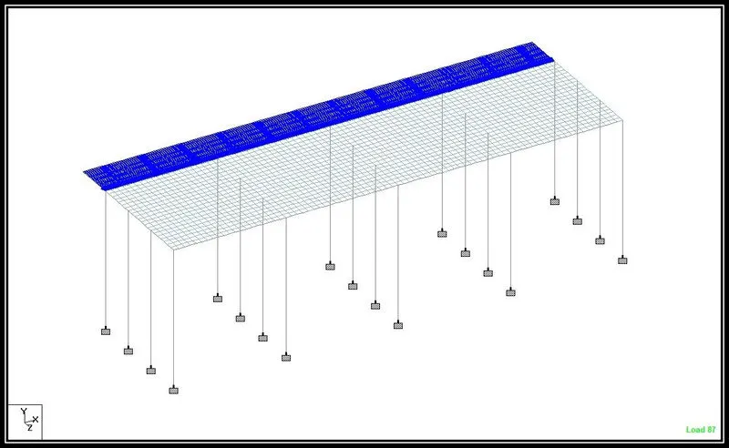
- Laoding --> Laod Cases Detail --> Add --> Case as ( Barge Impact Load) --> Add.
- Barge Impact Load --> Add --> Member Laod --> Uniform force --> W1 = 2483.87 kN/m , Direction as GZ --> Add
- Select Load --> Assign to selected beam --> Assign
Step (3) :- Analysis of Structure.
Load Assign on Structure.
- Go to Analysis and design option.
- Click on run analysis then analysis wll start.
- After analysis this window will come
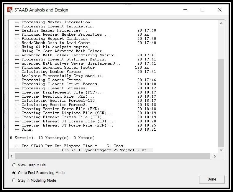
- To view the result click on post processing mode then done.
Result :-
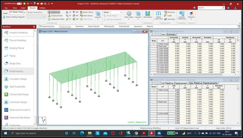
A) Bending Moment And Displacement Value for Water current Load
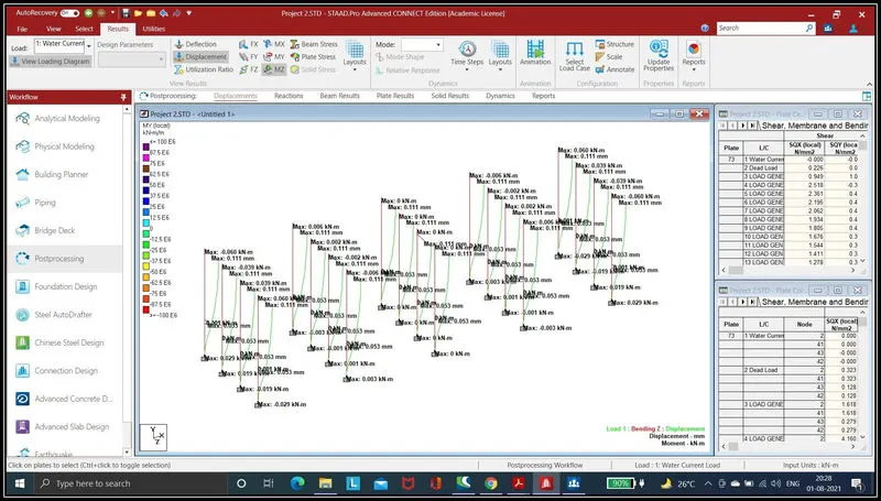
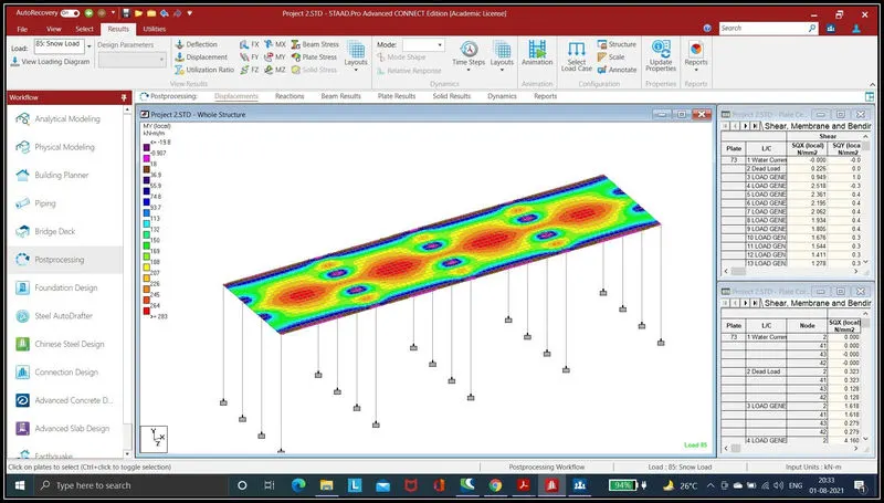
B) Plate Stress of snow load in MY local
C) TEmperature Stress in MX local