Week 10 Challenge
Aim :- To Create 10 meter span bridge model and applying snow load on deck as per IS 875 part 4 and perform analysis by using STAAD.pro software.
Mannual Calculation :-
Given,
- Density of Settled snow = 3 kN/`m^3`.
- Depth of snow = 1.250 M.
- Flat deck, angle `beta` = 0 degree.
Snow Load,
So = Density of snow X Depth of snow X span of bridge.
= 3 X 1.250 x 10
So = 37.5 kN/m
Shape Coefficient from IS 875 part 4
for angle `beta` < 30 degree, `mu` = 0.8
Design snow load.
S = `mu` X So
= 0.8 X 37.5
S = 30 kN/m
Analysis using STAAD.pro software :-
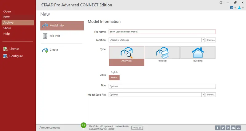
Step (1) :- Opening of STAAD.pro software.
- Open a STAAD.pro software.
- Fill all information rearding model in model information.
- Then click create to open the model.
Step (2) :- Creating Pier in model.
- Create first node using cordinate option after then create pier.
- For creating first pier select that node and copy them in Y direction using translational repeat option upto 7 meter height .
- (:. Height of the pier we assume 7 meter)
- Then select that pier using beam cursor and copy them in Z direction using translational repeat option.
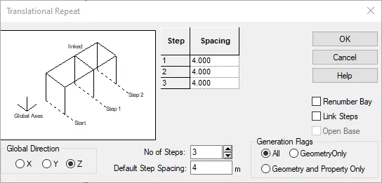
- In translational repeat option select global direction as Z and No of step should be 3 and spacing is 4 meter c/c then click ok to create.
- Again select all the pier which we created and copy them in X direction upto 10 meter using translational repeat option.
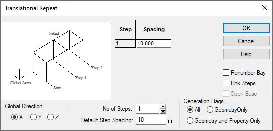
- Select Global Direction as X and spacing is 10 meter.
- Hence all piers is created.
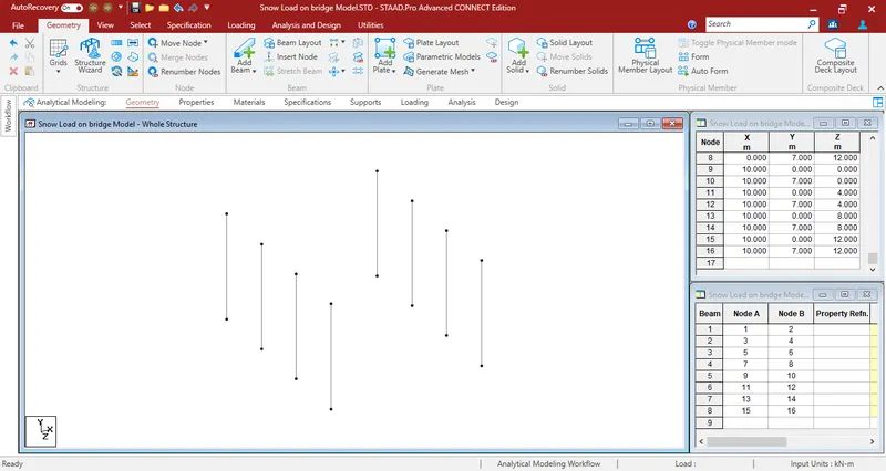
Step (3) :- Creating Grider and Crossbeam.
- For Creating girder & crossbeam go to geometry option and click on add beam
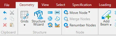
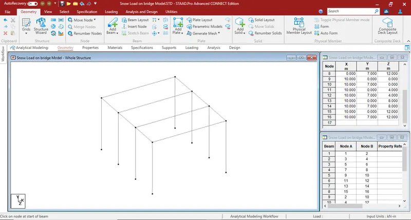
- Then connect all top node of the pier using add beam cursor.
- Connect all top node which is parallel to X and Z direction.
- Hence grider and crossbeam is created.
Step (4) :- Creating deck on bridge model.
- For creating deck we need to create one plate.
- For creating plate select top node of the first pier and copy it in X direction using translational repeat option upto 0.5 meter
- Again select both the node and copy them in Z direction upto 0.5 meter using translational repeat option.
- After that go to geometry and select add plate option and connect all the node which we created.
- Hence one plate is created.
- Select that plate using plate cursor option and copy them in X direction using translational repeat option.
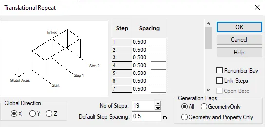
- 10 meter span is given so, No of step = 19 {10/0.5=20 nos. 20 - 1 (first plat)=19 }
- In translation repeat option select X as global direction and spacing should be 0.5 meter.
- After that again select all the plate which we created and again copy them in Z direction using translational repeat option.
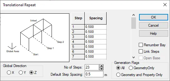
- Width of the birdge is 12 meter which is given, No of step = 23 {12/0.5 = 24 nos. (24-1 = 23)}
- Select global direction as Z and default step spacing as 0.5 meter.
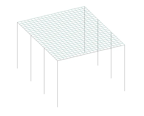
- In question 3 meter cantilever deck is given on both the side of the bridge.
- For creating cantilever deck select all first plate which is parallel to X direction and then copy them in Z direction using translational repeat option
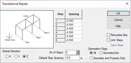
- Select direction as Z and No of step should be 6 ( Cantilever deck is 3 meter so, 3/0.5= 6 nos)
- And default spacing is -0.5 meter ( we are copying plate in inverse Z direction so consider - 0.5 as spacing).
- Repeat this same procedur in another direction for creating cantilever deck.
- Select direction as Z and spacing as 0.5 meter because we are copying all plate in global Z diection.
- Hence 18 meter width deck is created.
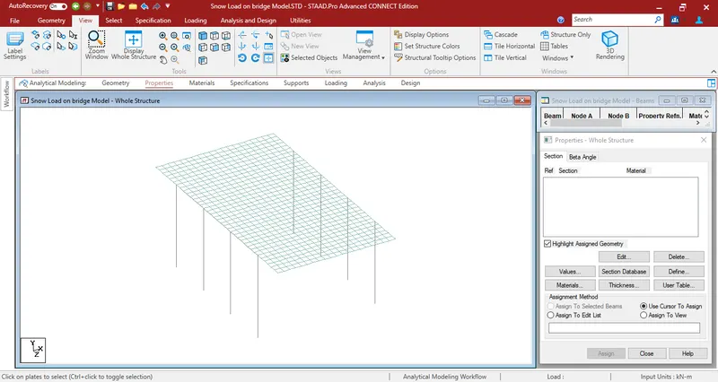
Step (5) :- Creating 1.5 meter height parapetwall.
- For creating parapetwall first we need to create one plate.
- For that select both node of the first deckplate which is parallel to X direction.
- And copy them in Y direction using translational repeat option upto 0.5 meter height.
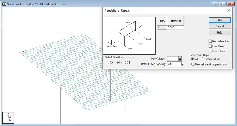
- Global direction as Y and No of step is 1 and spacing should be 0.5 meter.
- After that go to geometry and select add plate option.
- Connect all four node using add plate option hecne one plate is created.
- Select that plate using plate cursor option and copy them in Y direction using translational repeat option.
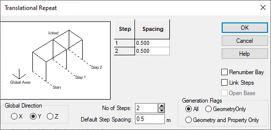
- Height of the parapetwall is 1.5 m so, 1.5/0.5 = 3, 3-1 = 2 no of steps.
- And select global direction as Y and spacing is 0.5 meter.
- After that select all three plate and copy them in X direction using translational repeat option.
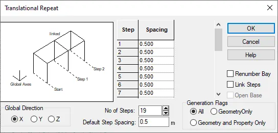
- Span of the bridge is 10 meter so, 10/0.5= 20 , 20-1 = 19 no of step.
- Select direction as X and spacing is 0.5 meter.
- Hence one side parapet wall is created.
- For creating parapet wall on another side above the deck repeat same procedure as mention above.

Step (6) :- Adding support to the model.
- For that go to specification then click on fixed support option then this window will open.
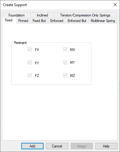
- In this window click on add option then this window will open.
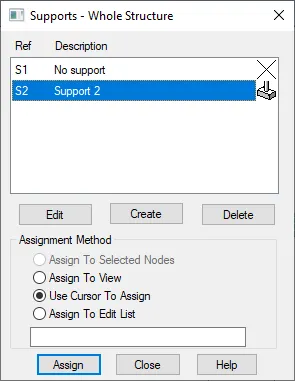
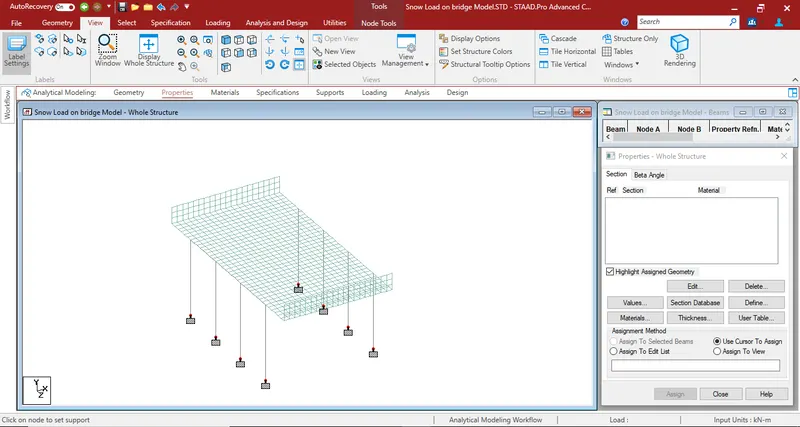
- First click on support 2 in above window then select buttom node of the all the pier.
- Select option as assign to selected nodes in above window and then click on assign button.
- Hence support is assigned to all the piers.
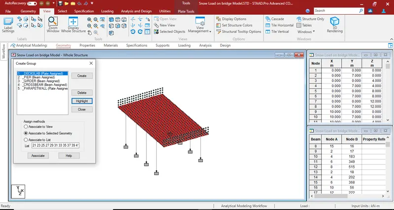
Step (7) :- Making group for each component.
- Creating group for any component first select that component ( eg. Deck) then press Ctrl + G Then define group name dialog box will appare.
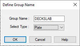
- In that box type group name as component name ( eg deckslab ) then select type and press ok.
- Then create group dialog box will open in that box select associate to selected geometry option then click on associate option for creating the group.
- For Crosscheck select that group and press highlight button grouping item will highlight.
- For another component repeat the same procedure as mention above.
- Select induidial component and make a group of it.
Step (8) :- Adding property to pier.
- First go to specification then click on prismatic option then property window will open.
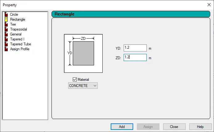
- In above window select rectangle and put the size of pier ( we assume 1.2 x 1.2 meter ) then click on add.
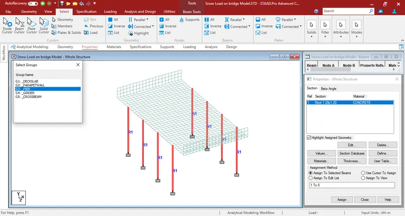
- Then select the pier by using grouping option as we created above.
- And assign this property to it.
Step (9) :- Adding property to girder and crossbeam.
- Go to specification then select prismatic option property window will open.
- In property window for girder component select tapared I section and fill size of girder as assume in below window.
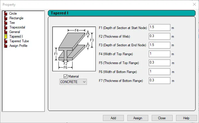
- Then click on add button.
- For crossbeam repeat same procedure as mention above and select rectangle option in property window.
- Assume size of crossbeam as 1.5 x 0.75 meter. then click on add option.
- First select all the girder and assign this tapared I section property to it.
- Then select crossbeam and assign crossbeam property to it.
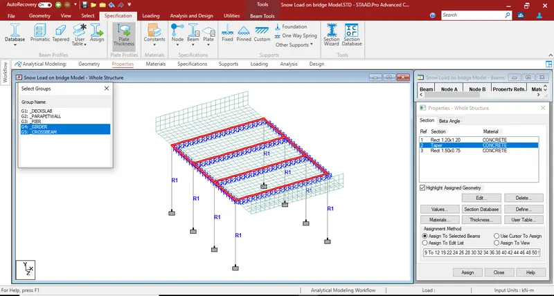
Step (10) :- Adding plate thickness to deck and parapet wall.
- Go to specification then select plate thickness option then plate element property window will open.
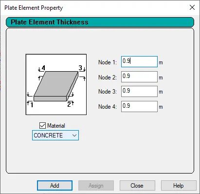
- In above window put 0.9 meter as plate thickness as given in question.
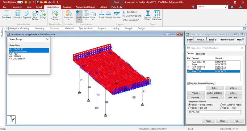
- After that select the deckslab by grouping method and assign this thickness property to it.
- For parapetwall repeat the same procedure as mention above but consider thickness as 0.350 m.
- Hence all thickness property is assigned.
( 3D model )
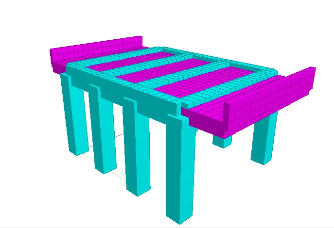
Note :- After creating model and assigning property to it crosscheck for multipal structure, duplicate option. etc. and also check missing property
Step (11) :- Applying snow load on deckslab.
- First go to loading option then in right side of window loading and defination window will shown.
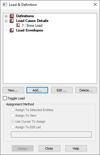
- In above window select load cases details then click on add option then this window will open.
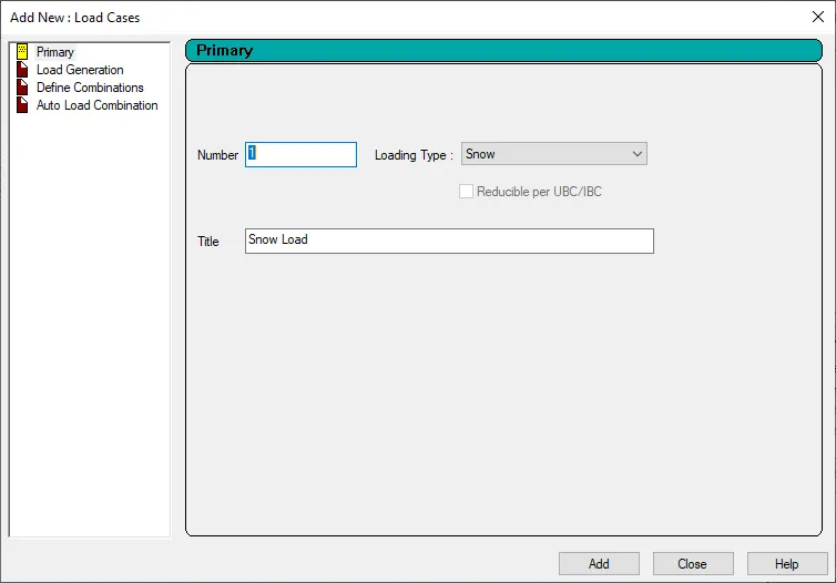
- Create load case 1 as snow load then click on add button load case one is created.
- Select that load case (snow load) and again click on add option then load item window will open.
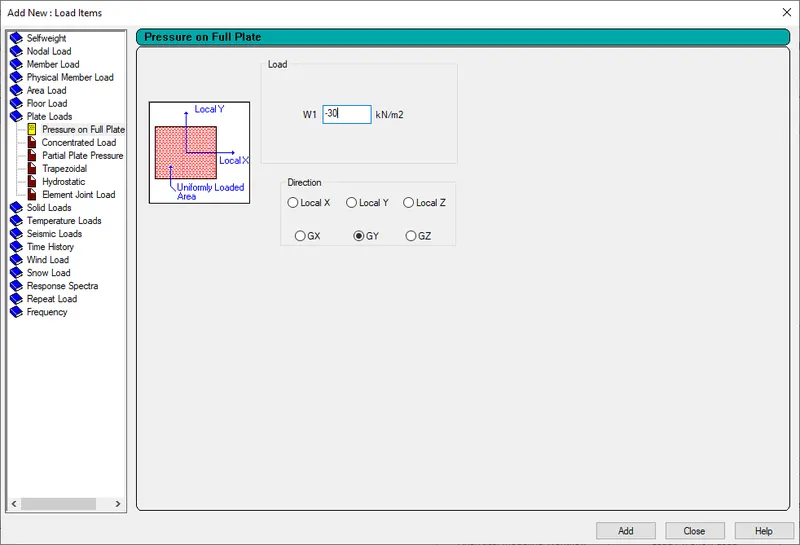
- In above window select plate loads option in that select pressure on full plate. and add W1 value as -30 kN/`m^3` ( value of W1 design snow load is calculated above in mannual calculation) and select direction as GY then click on add option.
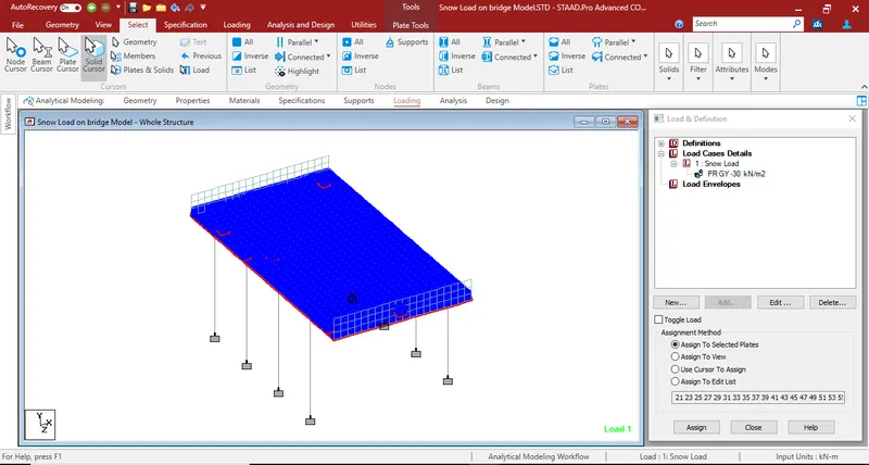
- Then Select that load and assign it on deckslab of the bridge.
- Hence snow load is assigned.
Step (12) :- Analysis of model
- For analysis go to analysis and design option.
- Then click on run analysis option, after that analysis process will start
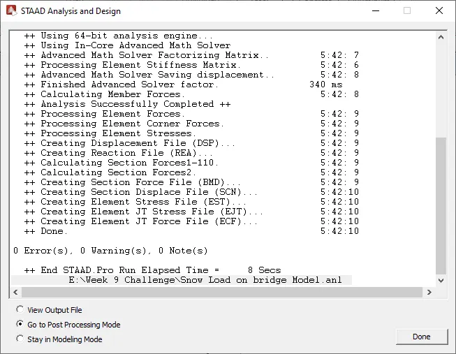
- For result select post processing mode then cilck on done button to view.
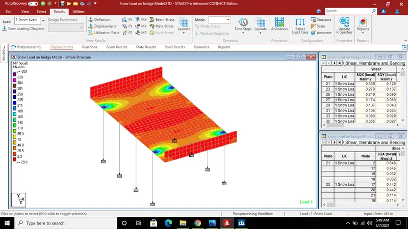
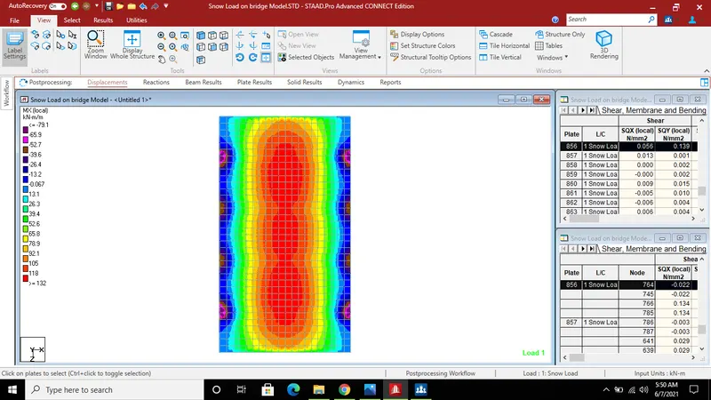
Results :-
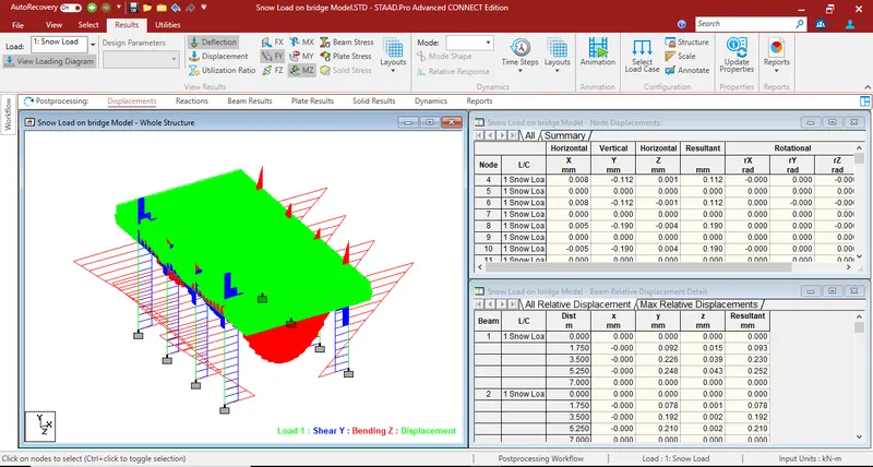
A) Bending Moment.
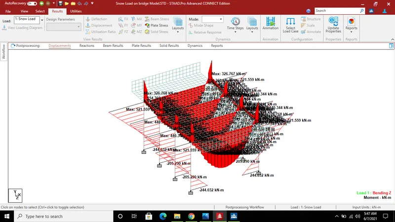
B) plate stress in MY and MX local