ANALYSIS ON A PLATE WITH A HOLE
AIM:
To perform Static Analysis on two modes of plates with holes. We have to create the model in Solidworks and perform the analysis.
OBJECTIVE:
To compare the performance of 2 separate plates with different hole geometries by performing a static structural analysis on plate with a hole using Solidworks Simulation and the determine the Stress, Strain and Displacement produced in the model on applying tensile force of 1000N on one side of the plate and fixing the other side of the plate.
CASE 1:
Length=300mm
Height=120mm
Thickness=30mm
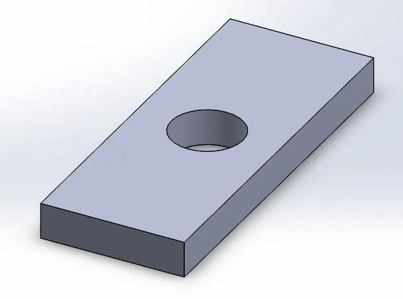
Circular Hole at the center: Diameter=60mm
STEPS OF CONSTRUCTION:
1) Select the required plane to sketch on Solidworks.
2) Click on Center Rectangle option from the Command Bar.
3) Draw a Rectangle of Length = 300mm and Breadth = 120mm. Adjust the Dimensions using the Smart Dimension Command.
4) Once the sketch is complete, Extrude the sketch to a distance of 30mm using the Blind option in Extrude command.
5) Now we get a solid rectangle of required dimension and now we need to place the hole on the plate.
6) We need to select the plane on which we are going to sketch the hole.
7) Once the plane is selected, using the Circle command we are sketching a Circle of Diameter 60mm.
8) Using the Extrude cut option, we need to cut a hole through the plate as shown above.
9) On doing so, we achieve the required model.
10) Images of steps of construction shown below
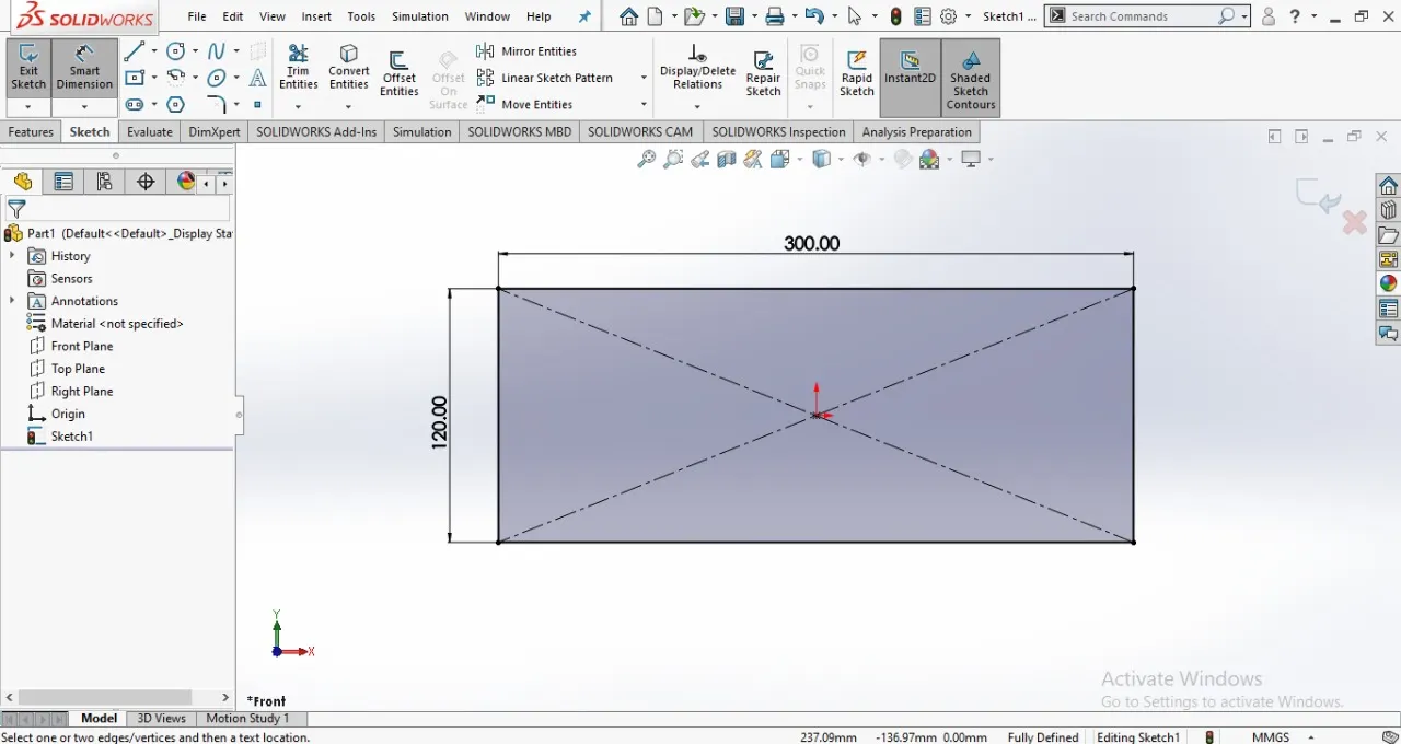
SKETCH OF PLATE IN 2D USING SOLIDWORKS
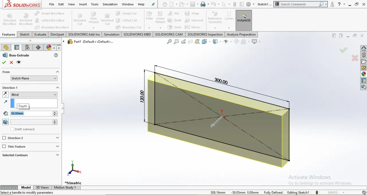
EXTRUDING THE SKETCH TO A DISTANCE OF 30mm TO CREATE A PLATE
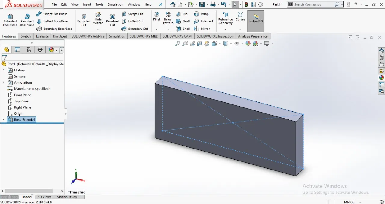
EXTRUDED MODEL OF PLATE WITH THICKNESS OF 30mm
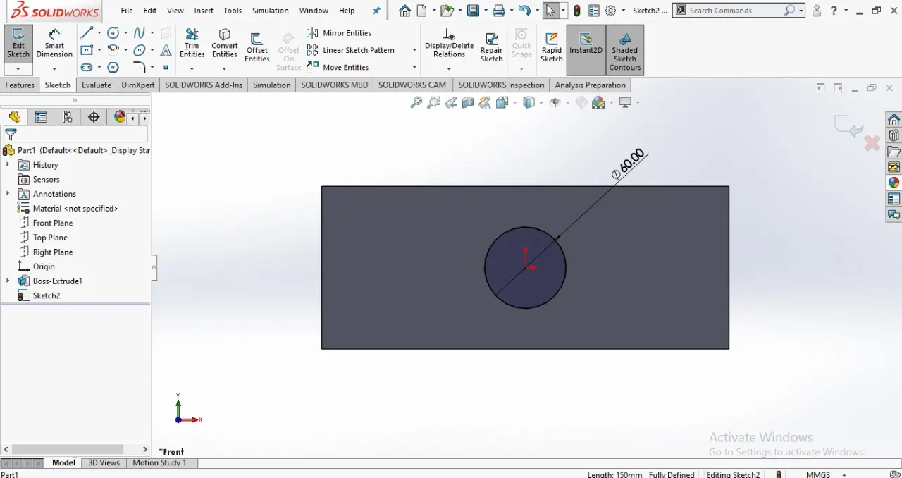
CREATING A SKETCH OF CIRCLE OF DIAMETER 60mm ON THE TOP PLANE OF PLATE TO CREATE A HOLE
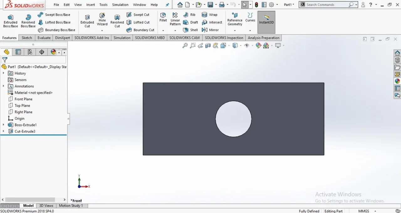
USING EXTRUDE CUT OPTION TO CREATE A HOLE IN THE PLATE
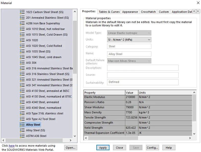
APPLYING ALLOY STEEL AS MATERIAL TO THE PLATE
On following this procedure, we have obtained the plate with a hole. Now we open a New Study to perform Static Analysis on the plate to find out the Stess, Strain and Displacement faced by the plate when a tensile load of 1000N is acting on it.
FEA PROCEDURE:
1) Once we created the model of plate with hole, we open a New Study and perform static analysis on the plate.
2) Using the fixtures command, we are applying fixtures to one end of the plate.
3) A load of 1000N is applied on the other side of the plate in the reversed direction to act as a tensile force.
4) On applying the load, we apply the fine mesh of 6mm to the model to run the study to obtain results.
5) The steps followed are mentioned below as images.
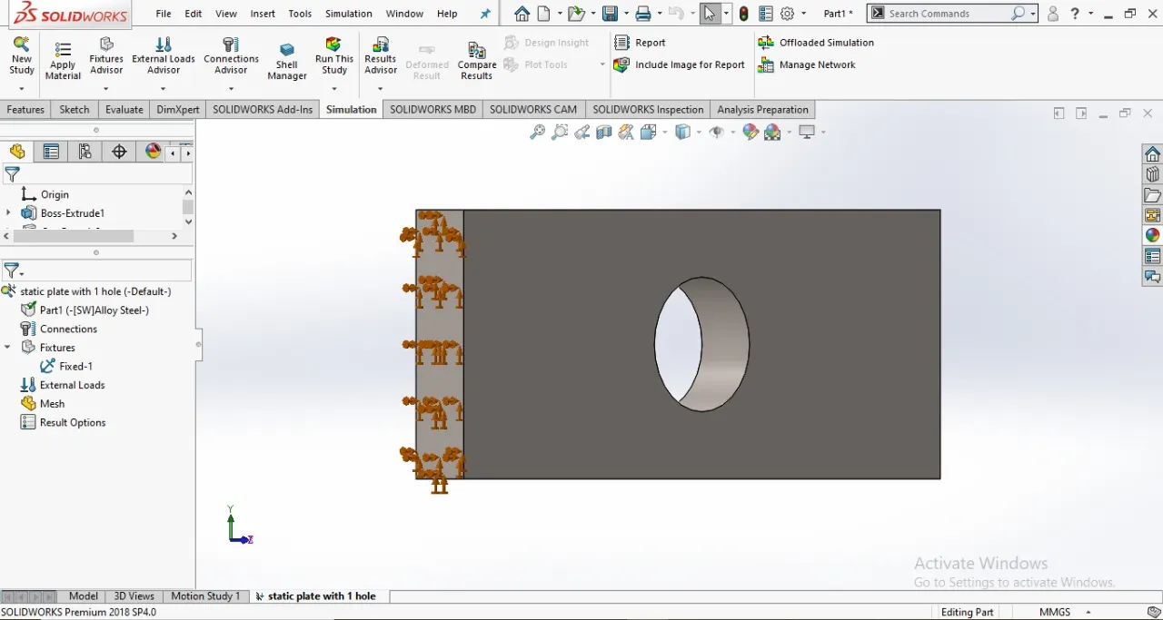
APPLYING FIXTURES TO ONE END OF THE PLATE
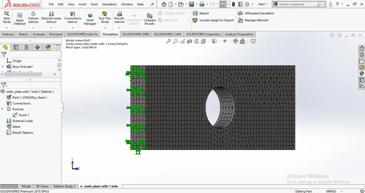
APPLYING A MESH OF 6mm TO THE MODEL TO RUN STUDY
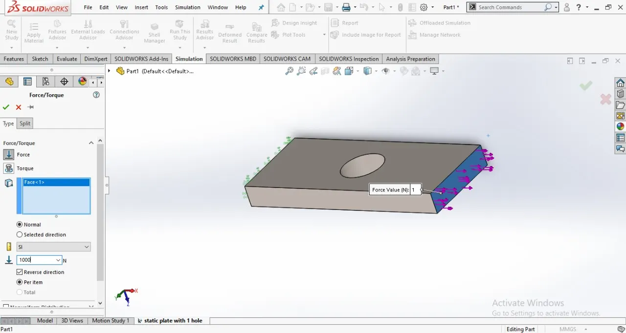
APPLYING LOAD OF 1000N TO OTHER SIDE OF THE PLATE WHICH ACTS AS A TENSILE FORCE
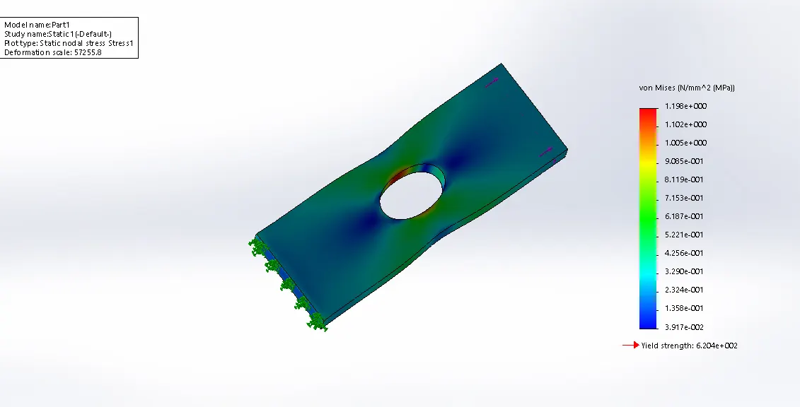
STRESS PLOT OBTAINED ON RUNNING THE STUDY
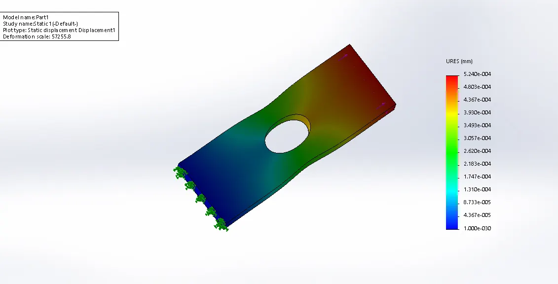
DISPLACEMENT PLOT
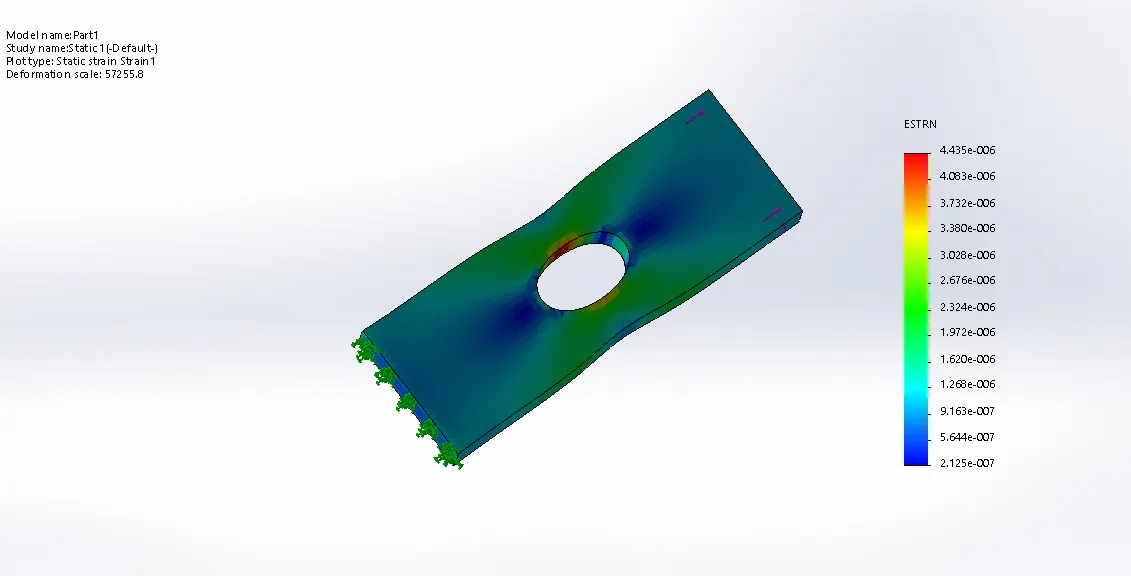
STRAIN PLOT
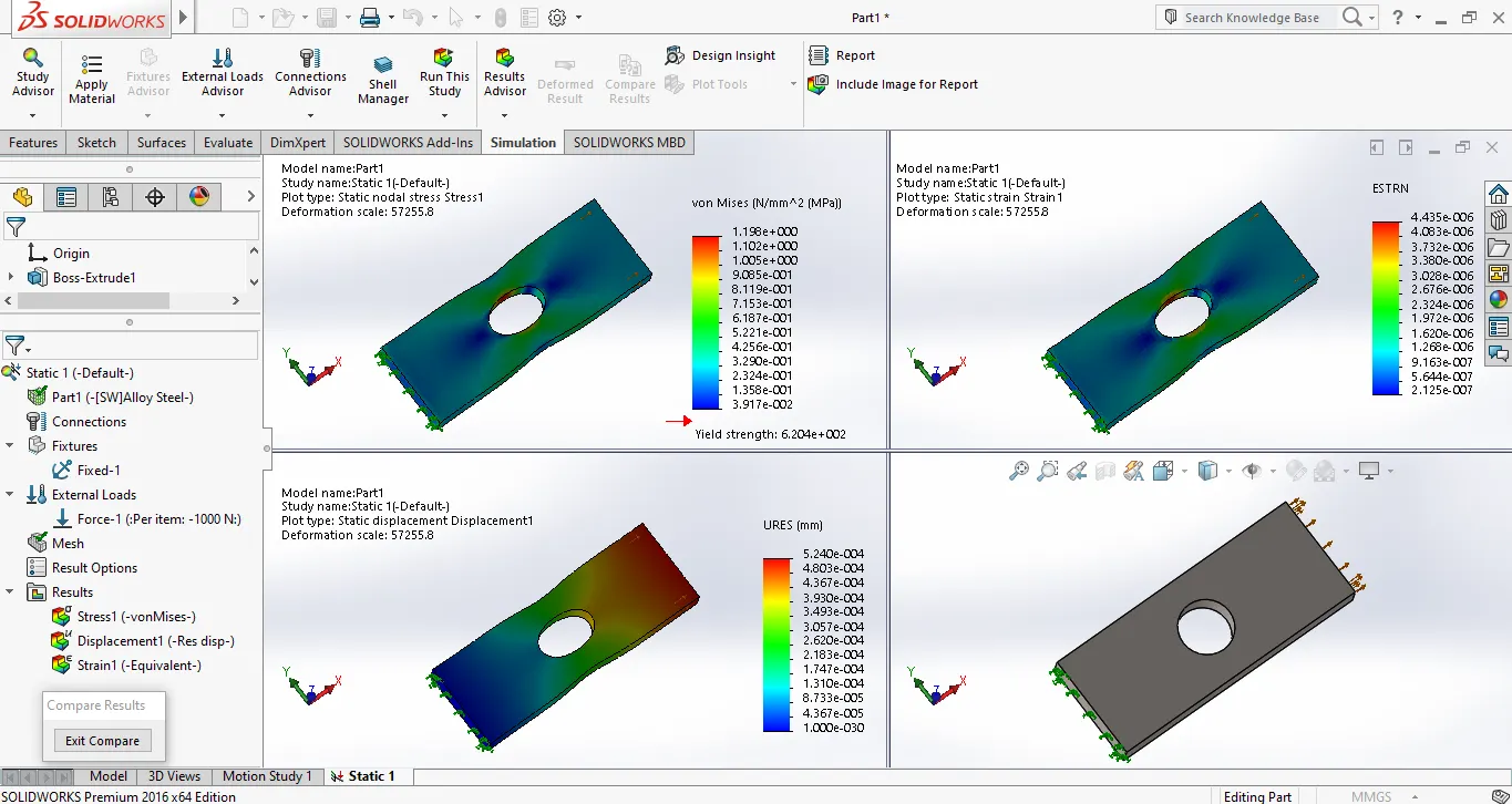
COMPARISON OF STRESS, STRAIN AND DISPLACEMENT PLOT IN SOLIDWORKS
Hence, from the results obtained above we can say that the study of static analysis on plate with 1 hole is complete.
CASE 2:
Length=300mm
Height=120mm
Thickness=30mm
Circular Hole at the center:
Diameter=60mm
Two holes of 30 mm diameter which are placed 90mm away from the central hole on both sides.
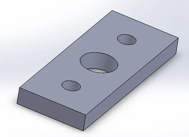
STEPS OF CONSTRUCTION:
1) Select the required plane to sketch on Solidworks.
2) Click on Center Rectangle option from the Command Bar.
3) Draw a Rectangle of Length = 300mm and Breadth = 120mm. Adjust the Dimensions using the Smart Dimension Command.
4) Once the sketch is complete, Extrude the sketch to a distance of 30mm using the Blind option in Extrude command.
5) Now we get a solid rectangle of required dimension and now we need to place the hole on the plate.
6) We need to select the plane on which we are going to sketch the hole.
7) Once the plane is selected, using the Circle command we are sketching a Circle of Diameter 60mm and at a distance of 90mm from the center we are sketching circles of diameter 30mm.
8) Using the Extrude cut option, we need to cut a hole through the plate as shown above.
9) On doing so, we achieve the required model.
10) Images of steps of construction shown below.
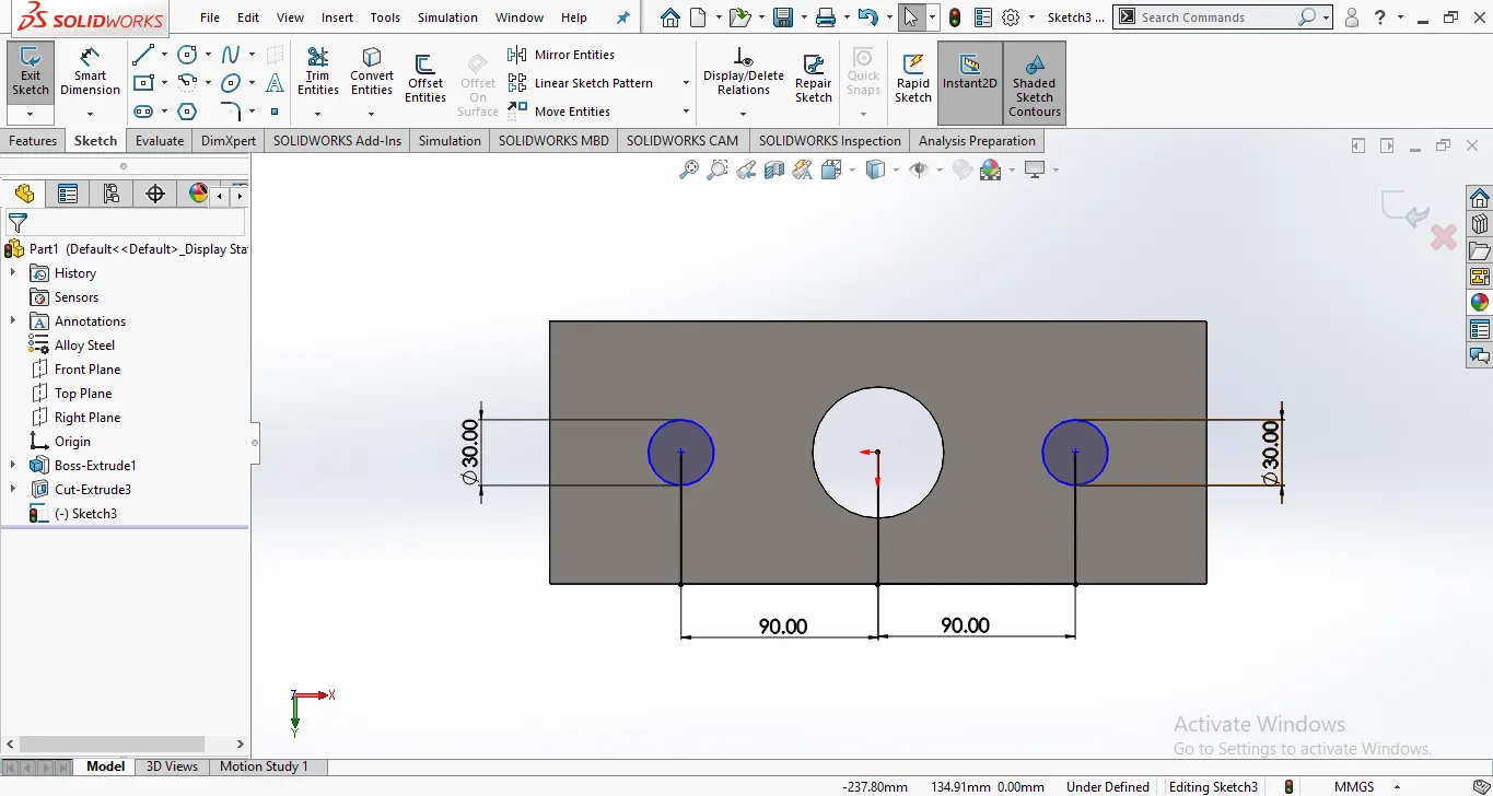
DRAWING 2 CIRCLES OF DIAMETER 30mm AT A DISTANCE 90mm FROM EACH OTHER
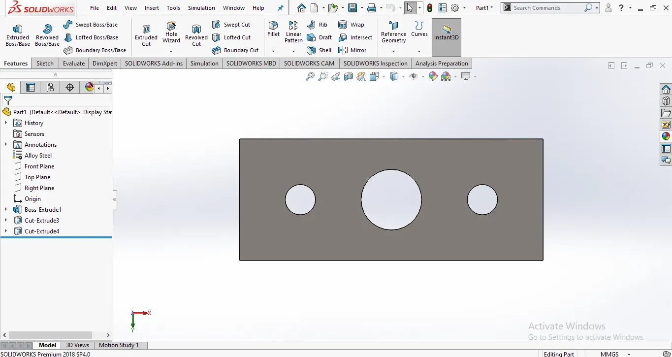
PLATE WITH 3 HOLES OBTAINED AFTER USING EXTRUDE CUT OPTION
FEA PROCEDURE:
1) Once we created the model of plate with hole, we open a New Study and perform static analysis on the plate.
2) Using the fixtures command, we are applying fixtures to one end of the plate.
3) A load of 1000N is applied on the other side of the plate in the reversed direction to act as a tensile force.
4) On applying the load, we apply the fine mesh of 6mm to the model to run the study to obtain results.
5) The steps followed are mentioned below as images.
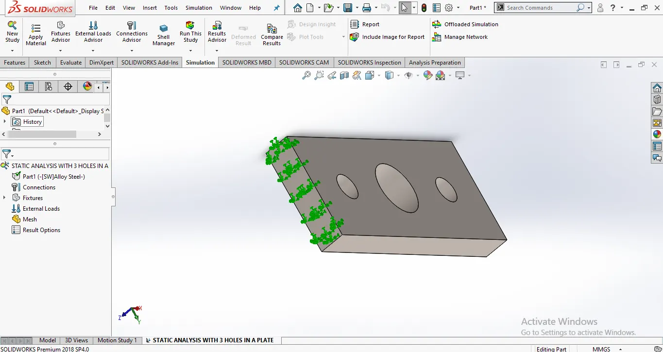
APPLYING NECESSARY FIXTURES TO ONE END OF THE PLATE
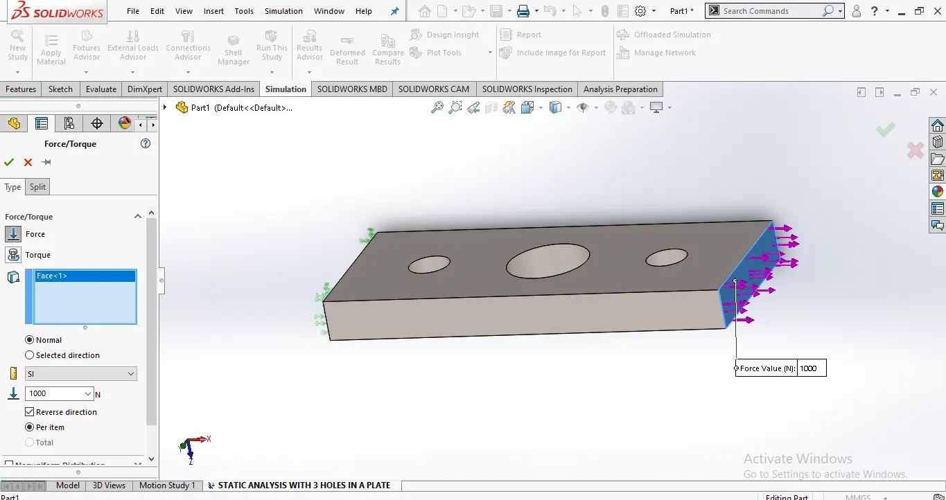
APPYING A TENSILE LOAD OF 1000N ON THE OTHER END OF THE PLATE
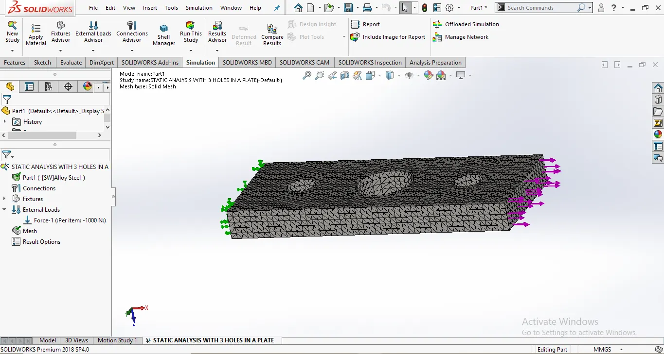
APPLYING FINE MESH TO THE PLATE TO RUN THE SIMULATION
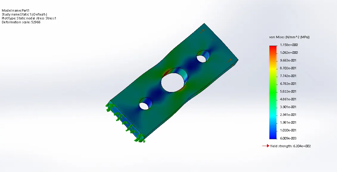
STRESS PLOT OBTAINED ON RUNNING STATIC ANALYSIS
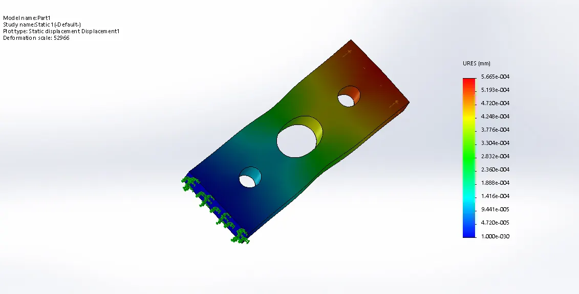
DISPLACEMENT PLOT OBTAINED ON RUNNING STATIC ANALYSIS
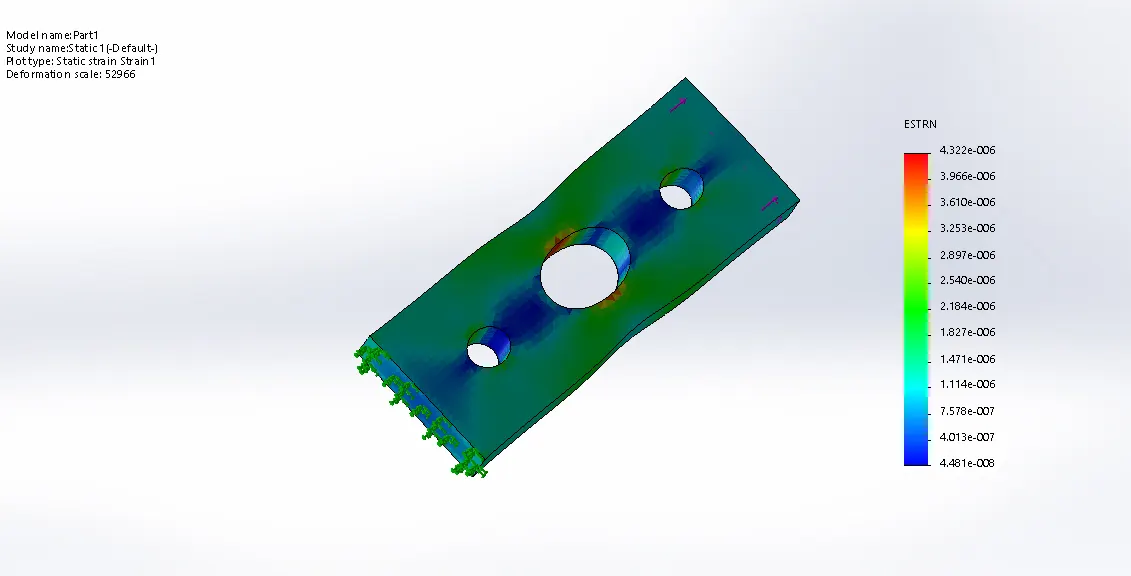
STRAIN PLOT OBTAINED ON RUNNING ANALYSIS
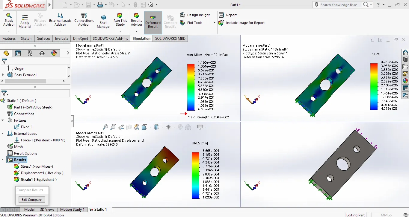
COMPARING THE RESULTS OF STRESS, STRAIN AND DISPLACEMENT OBTAINED IN THE STUDY
RESULTS:
The results obtained for case 1 are as follows:
1) Peak Stress in plate with 1 hole = 1.198 `frac{N}{mm^2}`
2) displacement value = 5.240 * `10^-4 mm`
3) Strain value = `4.435*10^-6`.
These are the values obtained for the simulation run in static analysis on a plate with 1 hole.
The results obtained for case 2 which is plate with 3 holes are as follows:
1) Peak Stress = `1.160 frac{N}{mm^2}`
2) Displacment = `5.665 * 10^-4 mm`
3) Strain = `4.289 * 10^-6`
CONCLUSION:
On comparing the 2 results, we can say that plate with 1 hole has higher peak stress compared to plate with 3 holes.
Plate with 3 holes has higher Displacement on comparison with plate with 1 hole.
The Strain value is found out to be higher in Case 1 than in Case 2.
Hence, on comparing both the cases we can say that plate with 3 holes is better than plate with 1 holes since the effect of stress, strain and displacement is slightly lesser than plate with 1 hole.