INTERNAL GENEVA MECHANISM USING MULTIBODY DYNAMICS IN SOLIDWORKS
AIM:
TO PERFORM MULTIBODY DYNAMICS ON GENEVA MECHANISM USING SOLIDWORKS.
OBJECTIVES:
1) To create 3d models of driver and driven components.
2) Perform motion analysis by rotating the driver wheel at 10 Rpm.
3) We must obtain the following plots:
Contact force(between driving and driven wheel) as a function of time.
4) Compare the contact forces with and without precise contact.
PROCEDURE FOR DRIVEN PART:
To perform Multibody dynamics on internal geneva mechanism, we need to design the driver and driven parts of this mechanism. We need to design the 3d part of the Driven part using Solidworks. The dimensions for the driven part are given below:
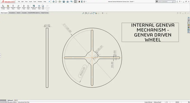
In order to design this, we need solidworks software. The unit system must be set to MMGS for providing acurate dimensions.
STEPS OF CONSTRUCTION:
1) A circle of diameter 1120mm is created.
2) It is then extruded to a distance of 40mm.
3) Selecting the fornt plane of the circle, we sketch the required slot for the driver part for ease of movement.
4) using commands like Slot, 3 point arc, circle command we were able to create the required slot for the driver component.
5) Once applying required features, we then extrude the sketch to a distance of 40mm. We get the required driven model.
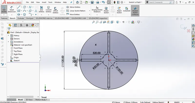
2D SKETCH OF THE DRIVEN COMPONENT
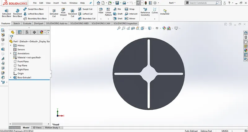
3D MODEL OF THE DRIVEN COMPONENT
PROCEDURE FOR DRIVER PART:
Similarly, we have to design the driver component. Using solidworks, we can design it according to the dimensions mentioned. The driver component is designed in the following method:
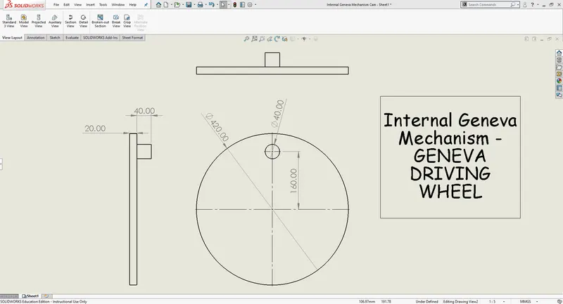
1) Draw a circle of diameter 420mm.
2) Extrude it to a distance of 40mm.
3) Select the top plane of the circle and draw a driver circle of diameter 40mm.
4) Extrude it to a distance of 40mm.
5) The steps are followed similarly in Solidworks as shown below.
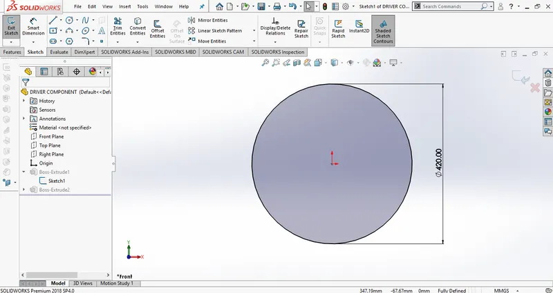
CIRCLE OF DIAMETER 420MM IS CONTRUCTED
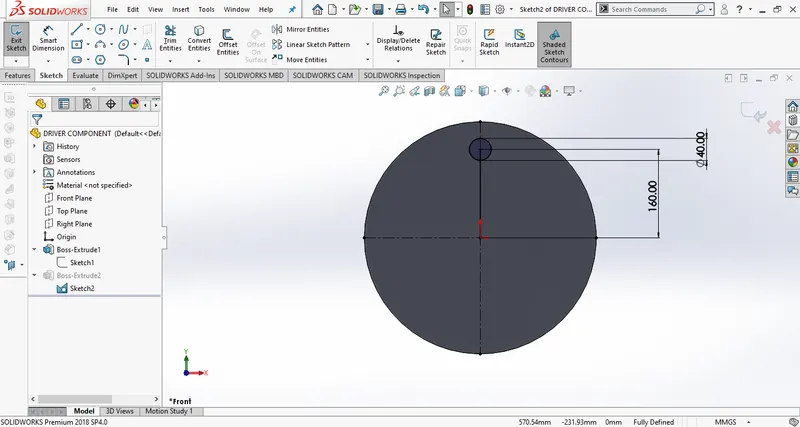
3D MODEL OF DRIVER COMPONENT IS MADE
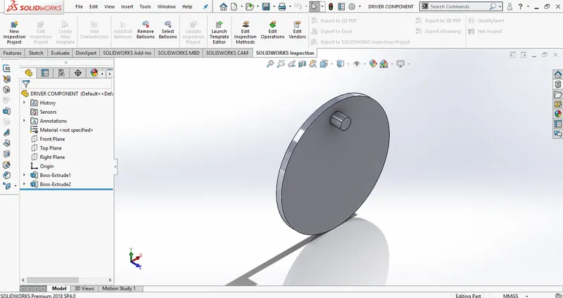
3D MODEL OF DRIVER COMPONENT
PROCEDURE FOR ASSEMBLY OF COMPONENTS:
The required driver and driven components are designed. Now, we need to assemble the two components using the Assembly section in Solidworks.The steps followed are mentioned below.
1) On opening solidworks, we must select the assembly section in new solidworks document.
2) We must import the driver and the driven components into the assmebly.
3) Upon doing that we must make the fixed components to float for ease in the assmebly process.
4) We are then using the plane of the assembly and the plane of the components to constraint their movements.
5) The temporary axis option is used in order to constraint movement in the parts.
6) Distance mate is then provided for proper movement of driver component into the driven component.
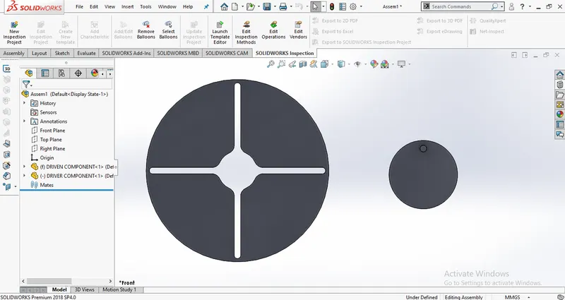
IMPORTING THE COMPONENTS IN THE ASSEMBLY SECTION
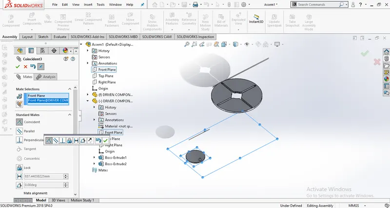
MATING THE DRIVER COMPONENTS FRONT PLANE TO THE ASSEMBLIES FRONT PLANE.
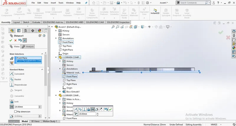
PROVIDING A DISTANCE MATE OF 20mm BETWEEN THE DRIVER AND DRIVEN COMPONENT.
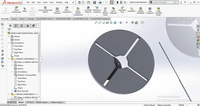
THE ASSEMBLED COMPONENT OF THE GENEVA MECHANISM
SIMULATION AND ANALYSIS:
To do simulation and analysis (i.e motion analysis) we are going to choose the Solidworks motion option from Solidworks Add-Ins. now we can see that the motion analysis option which is shown below in the window of Solidworks.To Rotate the Driving wheel we are going to assign motor for driving wheel. to do that select motor option in motion analysis and select part 1 axis. after that, we are going to assign solid body contact by selecting contact option and selecting part 1 and part 2. from Menu we can assign a material to the parts.To analyse multiple parameters, we can use a plot option in motion analysis, the plot results as follows
ANALYSIS AT 10 RPM:
The plot between contact force and time is shown below. The contact force is set between the driver and the driven for getting required plots.
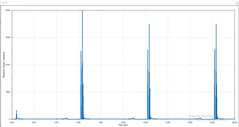
PLOT OBTAINED FOR CONTACT FORCE VS TIME AT 20S AT 10 RPM
PLOT FOR ANGULAR DISPLACEMENT VS TIME:
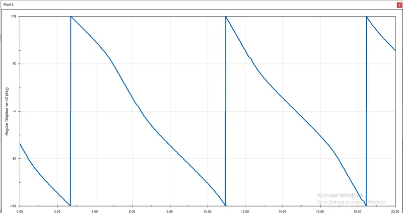
PLOT FOR ANGULAR DISPLACEMENT VS TIME IN GENEVA MECHANISM
CONTACT FORCES WITH PRECISE CONTACT:
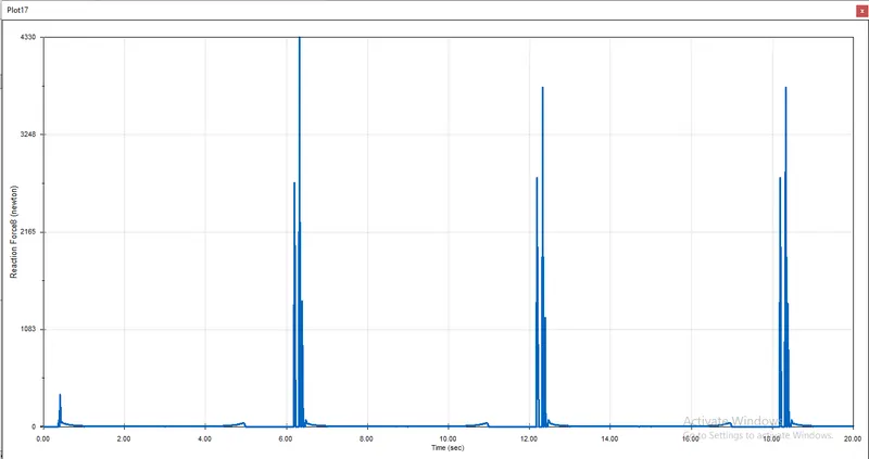
The graph for contact forces with precise contact shows us uniform jerks at regular intervals of time. Hence with precise contact, we can get more accurate results.
ANALYSIS AT 20RPM:
PLOT FOR CONTACT FORCE VS TIME AT 20 RPM
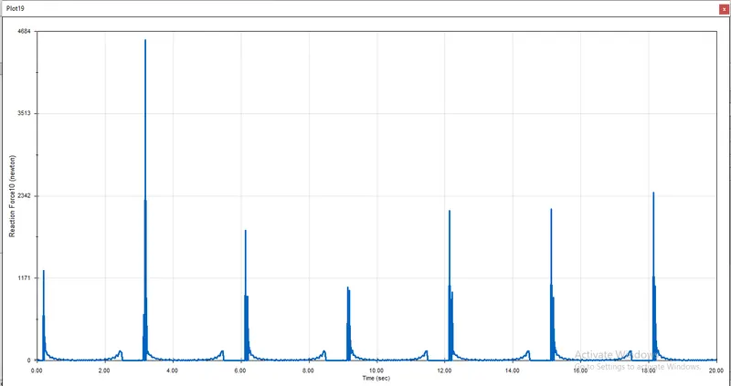
This plot is done between the contact forces and time taken which is 20 seconds. The speed of the motor is decided as 20RPM. The contacts are provided between the driver and driven components.On comparison with 10RPM, we can say that jerks have reduced.
ANGLULAR VELOCITY GRAPH:
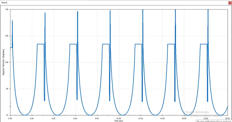
ANGULAR VELOCITY GRAPH IN THE DRIVER COMPONENT AT 20RPM WITH PRECIES CONTACT.
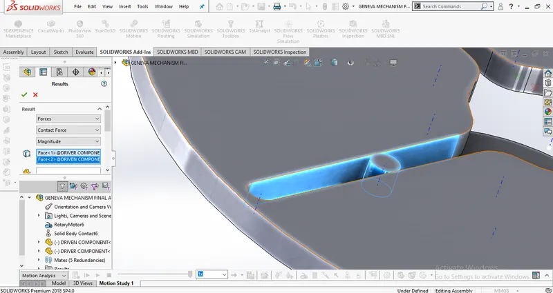
SURFACE SELECTION FOR CONTACT FORCE:
ANIMATION OF THE MODEL:
https://www.youtube.com/watch?v=Q0KAyk2KhGA
CONCLUSION:
When the driver tries to enter in the slot of the driven wheel it faces a jerk as the entry is not smooth. therefore, we can see from the plot, a sudden increase in the contact force at the entry to the slot. As we increase the rpm the angular displacement is also increased.