Planetary Gear Mechanism Using Solidworks
AIM: To perfrom motion analysis on Planetary gear mechanism with a carrier and to get required plot for the simulation performed.
OBJECTIVES:
Using the following inputs provided :
- Ring gear :
- Module = 2.5
- Number of teeth = 46
- Sun gear:
- Number of teeth = 14
- Input speed of the gear = 200 rpm.
- Number of planet gears = 4.
Simulations for the following conditions is to be performed:
| Sl.No | Input | Output | Fixed |
| 1 | Sun Gear | Carrier | Ring Gear |
| 2 | Ring Gear | Carrier | Sun Gear |
| 3 | Sun Gear | Ring Gear | Carrier |
COMPONENTS REQUIRED FOR SIMULATION:
1) 1 SUN GEAR
2) 4 PLANETARY GEARS
3) 1 RING GEAR
4) CARRIER FOR THE GEARS
| GEAR | MODULE | PITCH CIRCLE DIAMETER | NO. OF TEETH |
| SUN GEAR | 2.5 | x1 | 14 |
| PLANET GEAR | 2.5 | x2 | x4 |
| RING GEAR | 2.5 | x3 | 46 |
We need to calculate the values of x1, x2, x3, x4:
SUN GEAR:
Using the formula,
`m = frac{d}{t}`
Hence, 2.5 * 14 = d.
d`= 35mm`
PLANET GEAR:
On using the same formula,
We are assuming the number of teeth for the planet gear = 16 teeth.
2.5 * 16 = d.
d = 40mm.
RING GEAR:
Using the formula,
2.5 *46 = d.
d = 115mm.
| GEAR | MODULE | PITCH CIRCLE DIAMETER | NO. OF TEETH |
| SUN GEAR | 2.5 | 35mm | 14 |
| PLANET GEAR | 2.5 | 40mm | 16 |
| RING GEAR | 2.5 | 115mm | 46 |
Upon calculating the pitch circle diameter for each gear. Using Solidworks toolbox, we are using the gears with the required dimensions.
HOW TO USE GEARS IN SOLIDWORKS:
1) Go to toolbox in Solidworks.
2) We have to select the standard of the gears used.
3) ANSI INCH --> POWER TRANSMISSION --> GEARS --> SPUR GEARS.
4) Upon selecting the gear, we must provide the following parameters according the calculation to achieve the gears of required dimensions.
5) Module, Pitch circle diameter, Number of teeth, pressure angle and nominal shaft diameter.
6) On providing the necessary information, we can acquire the required gears.
SUN GEAR USED IN PLANETARY GEAR MECHANISM:
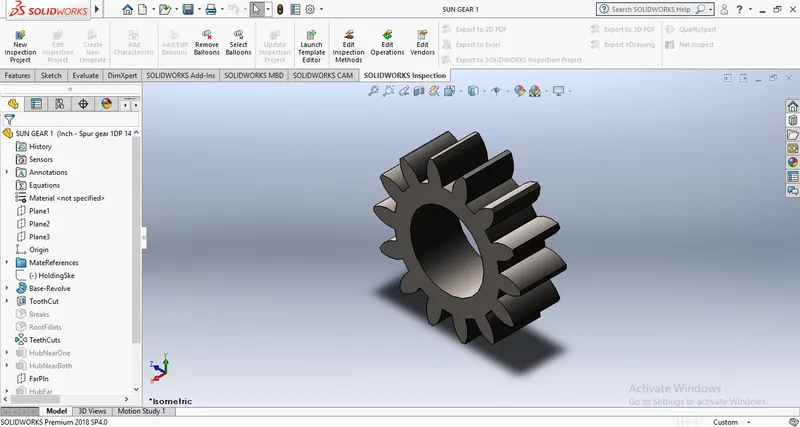
SUN GEAR
PLANET GEAR USED IN SOLIDWORKS:
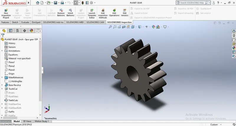
PLANET GEAR USED IN PLANETARY GEAR MECHANISM
RING GEAR USED IN PLANETARY GEAR MECHANISM:
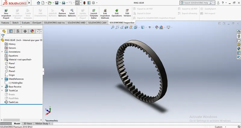
RING GEAR USED IN PLANETARY GEAR MECHANISM
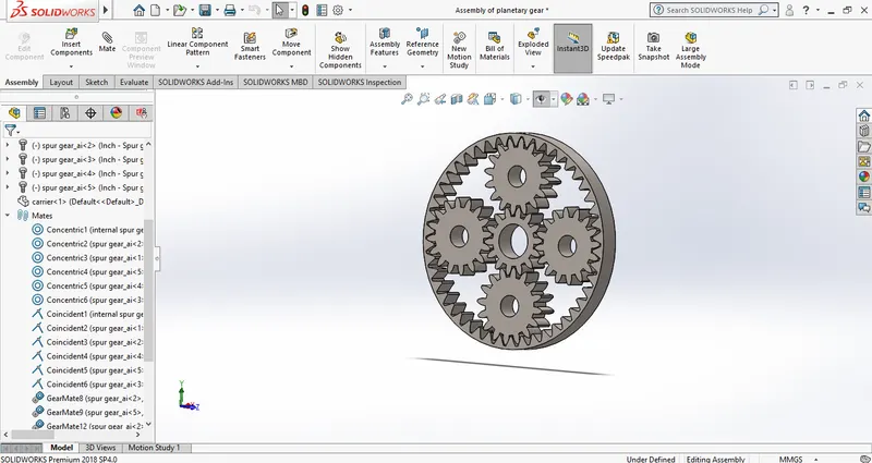
ASSEMBLY OF GEARS:
CARRIER USED IN SOLIDWORKS:
1) The sketch command in solidworks is used to make the carrier in the planetary gear mechanism.
2) Using commands like line, fillet, smart dimensioning, circle and trim entities we were able to create the sketch of the carrier.
3) The SI Unit system is kept to MMGS.
CARRIER MODEL IN SOLIDWORKS:
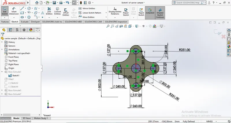
SKETCH OF CARRIER TO MAKE MODEL
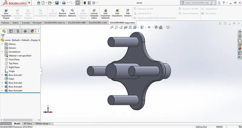
FINAL MODEL OF CARRIER
ASSEMBLY OF THE MODEL:
1) For the assemble of the gears, we are creating a sketch of a circle of similar dimensions to the gears used.
2) On doing that, we are super imposing the gear with the sketch to align the gears.
3) We are creating sketches for ring gear, planet gear and the sun gear.
4) Upon doing so, we are then aligning the gear under the same working plane. We have chosen right plane in this case.
5) Using gear mates command, we are providing relations between the sun and planet gear, planet and ring gear, sun and ring gear.
6) The model of the planetary gear mechanism is achieved.
MODEL OF THE PLANETARY GEAR MECHANISM:
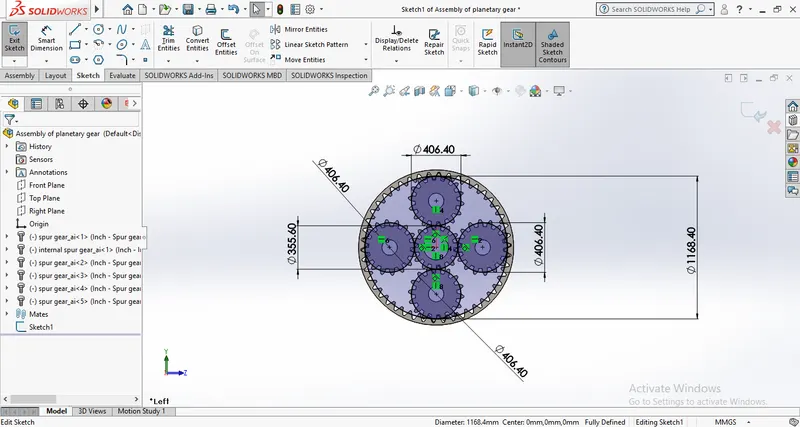
SKETCH USED TO DEFINE THE POSITION OF SUN, PLANET AND RING GEAR
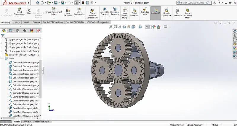
FINAL ASSEMBLY OF PLANETARY GEAR MECHANISM
PERFORMING MOTION ANALYSIS ON PLANETARY GEAR:
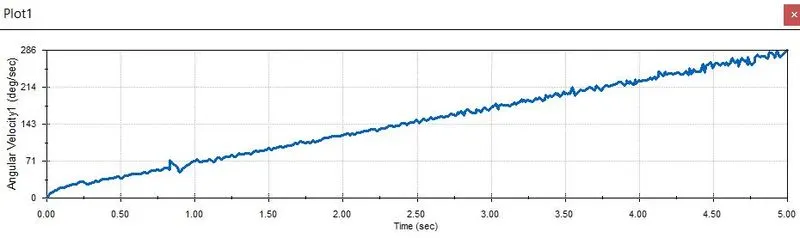
Case -1
Input = 200 rpm
Input part = Sun Gear
Fixed Part = Ring Gear
Output = Carrier shaft
RESULT:
Angular velocity variation with time with Case 1.
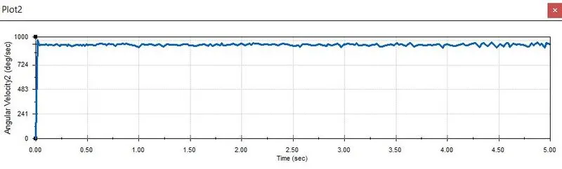
CASE 2:
Input = 200 rpm
Input part = Ring Gear
Fixed Part = Sun Gear
Output = Carrier shaft
RESULT:
Angular velocity variation with time in Case 2.
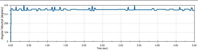
CASE 3:
Input = 200 rpm.
Input part = Sun gear
Fixed part = Carrier shaft
Output shaft = Ring gear
RESULT:
Angular velocity variation with time in case 3
RESULT:
Hence, the required plots for each case senario is obtained with results.
Drive file for part:
https://drive.google.com/drive/folders/1QVwsMWrpTjgp18-jYrKOZGXeKeTfr7x0?usp=sharing