Modified on
Simulating Flow through a Pipe Using OpenFOAM

Skill-Lync
The objective here is to simulate flow through a cylindrical pipe. Pipe flows have been studied extensively and are very vital in studying fluid mechanics.
The governing equation for flow through a pipe can be easily derived by applying key assumptions regarding the flow field. Such a simplified equation is called the Hagen–Poiseuille equation.
We are interested in simulating the flow through a pipe and then comparing the simulation results against the result obtained by solving the Hagen–Poiseuille equation directly. A good CFD code should do this without any problems.
Steps to be done
- Understanding the theory behind pipe flow
- Using the Hagen-Poiseuille equation to calculate the entry length of the pipe.
- Calculate the pressure drop using Hagen-Poiseuille
- Design a pipe in OpenFOAM and simulate flow through it by following the given steps:
- Geometry preparation
- Meshing
- Setting up of Boundary conditions
- Solver selection
- Post-processing
- Discussing results
Theoretical Background

Considering a laminar fluid flow inside a pipe. The surface contact between the water and the wall of the pipe will cause the water molecules to slow down and come to a complete stop near the walls. This layer of water molecules will also cause the adjacent layer of water flow to slow down due to the result of friction. To compensate for this velocity, water drops in the core of the pipe needs to maintain a constant velocity to keep the volumetric flow rate constant. As a result, the velocity boundary layer develops along the boundary walls of the pipe and starts to develop in the flow direction until it hits the center of the pipe. The distance from the pipe inlet to the point where the boundary layer merges is called the hydrodynamic entry length. The region beyond the hydrodynamic entry length is known as the fully developed region.
Calculating the entry length and pressure drop in the pipe
Formulas Used:
Entry length (L_E): 0.06*Re*D
Average velocity(Vavg): Re.m/ρ.D
Max Velocity (Vmax): 2*Vavg
Pressure difference (DP) = 32*m*L*Vavg/D2
where,
Re – Reynolds Number
D – Diameter of the pipe
µ – Dynamic viscosity
L – Length of pipe
ρ – Density
Calculations:
On calculating the pressure difference, here are the values used and the results obtained:
| Constant parameters | Values | Units |
| Reynolds Number | 2100 | |
| Diameter of pipe | 0.015 | m |
| Dynamic viscosity | 8.90E-04 | pa.s |
| Density | 997 | kg/m^3 |
| Calculated parameters | Values | Units |
| v_avg | 0.1249749 | ms^-1 |
| v_max | 0.2499498 | ms^-1 |
| Entry_length | 1.89 | m |
| Total_Length | 2.89 | m |
| Pressure_drop | 29.898001 | pa |
| kinematic_pressure_drop | 0.029988 | m |
Geometry Development:
Software used: OpenFoam
- The utility used to mesh the pipe – SnappyhexMesh
- The solver used to simulate flow –pimpleFOAM (for compressible flow)
The Geometry is developed using CAD software using the diameter and length mentioned above.

All the patches have been exported as a separate .stl file.
Solver Selection
A solver basically tells us what mathematical equations are solved and how they are being solved. The choice of solver is very important. You need to exactly know what equations are relevant to your problem. A wrong solver will invariably lead to wrong results. In this case, we are using a solver called pimpleFOAM. Each and every solver has its own settings. Meaning, the number of setting files that are required for a given problem changes with the solver.
OpenFOAM makes it easy for the user to understand what additional setting files are required for any given solver. They do this by providing solver specific tutorial files. You as a user should first determine the solver that you want and then grab the example that OpenFOAM provides and modify it to suit your needs.
You might wonder how many files you would need to set up the pimpleFOAM solver. Here are the specifics:
To run a basic pimpleFOAM program, assuming the mesh, turbulence properties, initial and boundary conditions have been set up, you will need to setup three files: System, constant, and 0 (zero) file.
- System files – FVschemes, FVsolutions, controldict
- Constant – Polymesh, transport properties, turbulence properties
- 0 – U, V, T (k, e, nut, alpha based turbulence)
Meshing:
In CFD, the entire 3D geometry has to be broken down into individual volumes – Finite volume cells. Inside these volumes, critical governing equations are solved. In OpenFOAM, we will be using the snappyHexMesh utility to create these finite volumes. In the image below, you can see the see volumes in our pipe geometry. Notice, how the shape of these volumes, change as you go from the centre to the circumference of the pipe inlet. Near the centre, the volumes appear cubic and this shape is called as hexes. This is what the snappyHexMesh tool does. It tries to create hexahedral (cubical) cells as much as possible in the interior.
In OpenFOAM, we need the following files to use the snappyHexMesh utility
- Geometry (.stl file)
- Settings file – snappyHexMeshDict
The geometry is taken to the folder triSurface where it is specified in the snappyHexMeshDict file. The file structure for the triSurface path can be found below:
 The geometry is then meshed using the snappyHexMesh utility.

The meshed geometry of the pipe
Setting up the Boundary Conditions:
Boundary conditions are very important in CFD. They help us in specifying “known conditions” to the solver. In this example, we have calculated the inlet velocity, specify this inlet velocity is what you would call as “assigning the boundary conditions”.
The number of boundary condition, their types and values are problem specific. That is why, you need to be able to calculate them for the problem that you are simulating.
In our case, we specify the velocity boundary condition by editing the file “0/u” Here, 0 refers to the folder that contains the initial values. U refers to the file that contains the initial velocity.
The below snapshot is clipped from the dictionary file and displayed for reference:

Next, we have to input the pressure. This can be done by editing the file 0/p.

The Simulation is started up by running the command pimpleFoam.
Simulation Result:
The results obtained from the simulation is as follows:
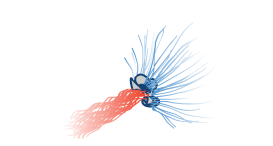
The velocity of the fluid near the inlet:

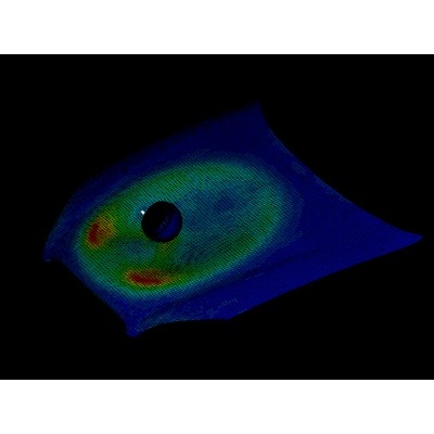
The velocity of the fluid after entry:

This is in accordance with the theoretical explanation above. The difference between the velocity in the boundary layer and the core is less near the inlet as compared to the fully developed region. At the fully developed region, the volumetric flow rate gets steady and the maximum velocity is achieved.
Result:
The Solution for the pressure drop (p1-p2) after the flow fully developed is found.
| Analytical Result | 0.029988 Nm2/s |
| Simulation result | 0.028754 |
Note: The pressure calculated is kinematic pressure. The Simulation done here is only Laminar and in real life, the flow is always turbulent. The above-mentioned equations are valid only for Laminar flows
Conclusion:
Thus, we have set up a CFD simulation in OpenFOAM. Though the simulation is basic, we have conveyed the fundamental concepts of the process.
You can leave your details below with Skill lync and we will share the geometry files (.stl) with you. (Note – the .stl files are locked on according to the dimensions mentioned above and therefore can be used for reference only)
Check out List of Job opportunities for your Engineering Domain
Author

SugavaneshM
Author
Skill-Lync
Subscribe to Our Free Newsletter

Continue Reading
Related Blogs
Explore the fundamentals of vehicle dynamics and ultimate trends in the field from design and modeling to control with Skill Lync's exclusive course on the subject. Read about how Skill-Lync's CAE courses can help you get employed.
28 Jul 2020
In this article, we will briefly discuss the working, applications, and features of the one-dimensional systematic simulation tool, GT-Power, in Emission Control Strategy, engine calibration, hybrid vehicle modeling. Read about how Skill-Lync's CAE courses can help you get employed.
28 Jul 2020
This article offers a brief introduction to the globally accepted standard of Geometric Dimensioning and Tolerancing, and its importance for the entire manufacturing process. Read about how Skill-Lync's CAE courses can help you get employed.
28 Jul 2020
In this blog we will read about Going a step into Biomechanics and how Skill-Lync's CAE course will help you get employed.
09 May 2020
The powertrain is the most prominent source of vibrations that affects the driving experience for the people on board. This blog from Skill-Lync examines these vibrations to help enhance that experience.
21 Aug 2020
Author
Skill-Lync
Subscribe to Our Free Newsletter
Continue Reading
Related Blogs
Explore the fundamentals of vehicle dynamics and ultimate trends in the field from design and modeling to control with Skill Lync's exclusive course on the subject. Read about how Skill-Lync's CAE courses can help you get employed.
28 Jul 2020
In this article, we will briefly discuss the working, applications, and features of the one-dimensional systematic simulation tool, GT-Power, in Emission Control Strategy, engine calibration, hybrid vehicle modeling. Read about how Skill-Lync's CAE courses can help you get employed.
28 Jul 2020
This article offers a brief introduction to the globally accepted standard of Geometric Dimensioning and Tolerancing, and its importance for the entire manufacturing process. Read about how Skill-Lync's CAE courses can help you get employed.
28 Jul 2020
In this blog we will read about Going a step into Biomechanics and how Skill-Lync's CAE course will help you get employed.
09 May 2020
The powertrain is the most prominent source of vibrations that affects the driving experience for the people on board. This blog from Skill-Lync examines these vibrations to help enhance that experience.
21 Aug 2020
Related Courses