Modified on
Comparison of stress concentration on plates with different number of holes

Skill-Lync
Introduction:
Does stress act differently on a structure depending on how many cuts or holes are present in it? Does a structure’s deformation depend on the number of cuts or holes present in it? To find out the answers, we will be designing two similar plates in this project, with similar dimensions and material, and then simulate them in ANSYS. The only difference being that one of the plates will have more holes than the other. From the results obtained, we will be able to compare how the varying number of holes in an element can affect its stress-bearing ability.
Objective:
To perform static structural analysis on two plates of the same dimensions but with a different numbers of holes and analyze the stress, deformation etc. acting on the plates.
Steps to be done:
- Case 1:
- Design Plate A with a single hole
- Meshing
- Case 2:
- Design Plate B with 3 holes
- Meshing
- Compare the simulation results
Case 1:
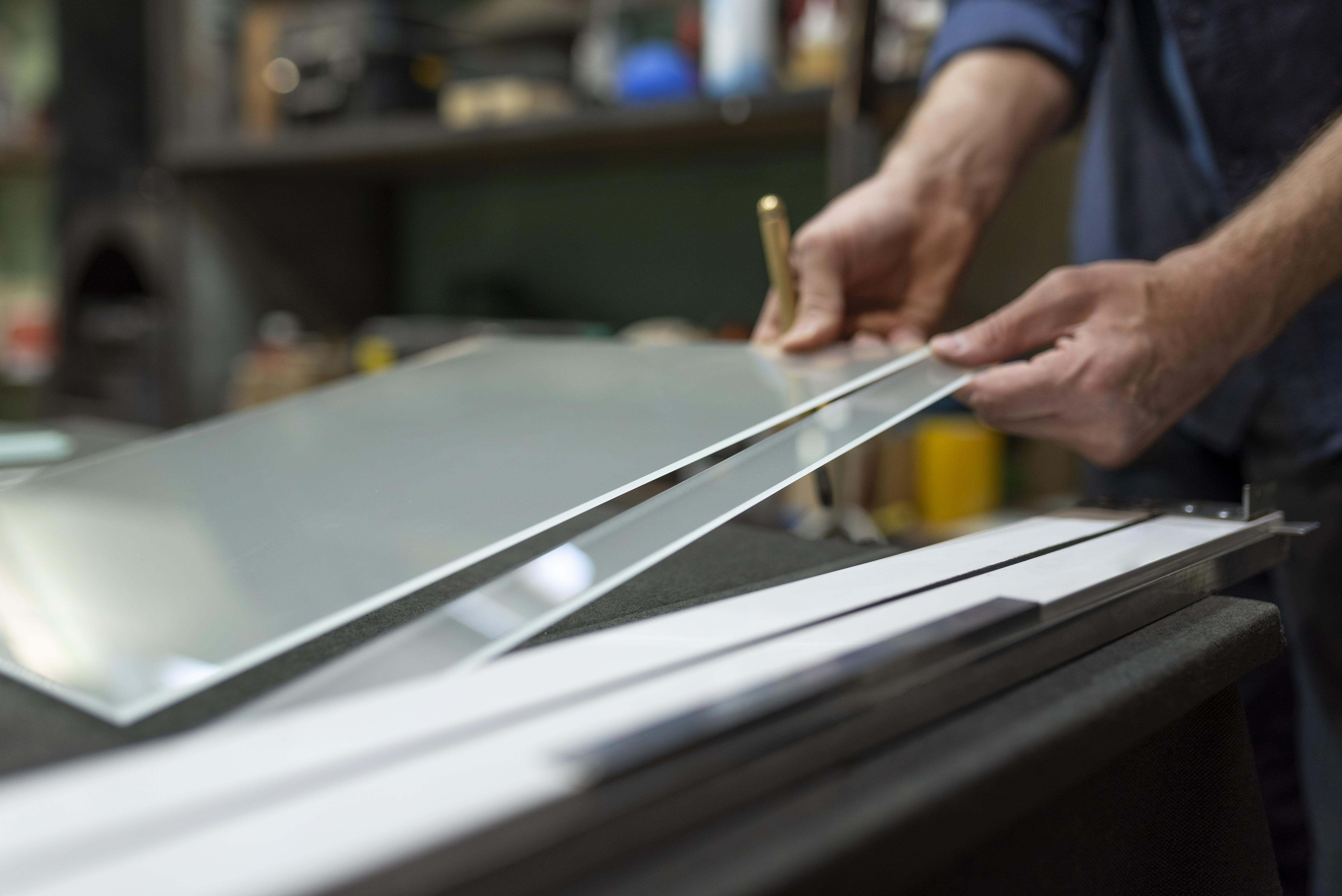
Designing Plate A with a single hole:
Software used: ANSYS SpaceClaim
The plate is modelled with the following dimensions:
| Length | 300mm |
| Breadth | 120mm |
| Thickness | 30mm |

A single hole of diameter 60 mm is designed at the centre of the plate. The material used here is Structural Steel. The properties of the material used are as stated below:
| Density | 7.85e-006 kg mm-3 |
| Isotropic Secant Coefficient of Thermal Expansion | 1.2e-005 C-1 |
| Specific Heat Constant Pressure | 4.34e+005 mJ kg-1 C-1 |
| Isotropic Thermal Conductivity | 6.05e-002 W mm-1 C-1 |
| Isotropic Resistivity | 1.7e-004 ohm mm |
The 2D geometry is then extruded within SpaceClaim to get the model to be imported into ANSYS. The extruded model is as shown in image below.

Meshing:
The model is now meshed using ANSYS meshes with an element size of 6.8mm. The Patch Conforming method using tetrahedrons was employed. This is done to get the best refinement within the limitations of an ANSYS Academic License.

A mesh metric that identifies elements according to their quality was employed and it can be seen that the elements of the lowest quality are minimal. Most of the elements have very high quality in the range of 0.7 to 1. Hence, the mesh is of acceptable quality. The meshed model is as shown in the image below.

After the model is meshed, the loads are applied on the model. A fixed support is given on one side while a tensile load of 500 N is given on the other. The loads are as shown in the image below:

The Simulation is then run with the settings applied and the results are obtained.
Case 2:
Designing Plate B with 3 holes:
Software used: ANSYS SpaceClaim
The plate is modelled as in Case 1, with the same dimensions:
| Length | 300mm |
| Breadth | 120mm |
| Thickness | 30mm |
Instead of a single hole like we did in case 1, we now design 3 holes in the plate. It is a modification of the model used in Case 1 such that there are 2 extra holes of 30mm diameter placed 90mm away from the centre. The 3D model of the plate is as shown in the image below.

Meshing:
The model is meshed using ANSYS mesher. An element size of 3.31 mm and a Patch conforming method using tetrahedrons was implemented. The number of nodes and elements can be seen to not exceed the license limits.

A mesh metric that identifies elements according to their quality was employed and it can be seen that the elements of lowest quality are minimal. Most of the elements have very high quality in the range of 0.5 to 0.9. Hence, the mesh is of acceptable quality. The meshed model is as shown in image below.

After meshing of the model, the loads are applied.

“Fixed Support” is applied on one side of the model and a tensile load of 500 N is applied on the other side. The simulation is then run and the results are obtained.
Results:
The Total Deformation for the two cases are compared first.
| Time [s] | Minimum [mm] | Maximum [mm] | Average [mm] |
| 1. | 0. | 2.7489e-004 | 1.3726e-004 |
| 2. | 0. | 2.9721e-004 | 1.4589e-004 |
The Equivalent stress for the two cases are compared.
| Time [s] | Minimum [MPa] | Maximum [MPa] | Average [MPa] |
| 1. | 1.7299e-002 | 0.59312 | 0.15875 |
| 2. | 1.103e-003 | 0.57732 | 0.16697 |
The Equivalent stress is plotted on the model and you can view the simulation below:
A comparison of the equivalent stress acting on the two plates:

The Total Deformation is plotted on the model and you can view the simulation below:
A comparison of the deformation acting on the two plates:

Conclusion:
The analysis was run successfully. Within the limits of the academic license, the simulations for the 2 cases were examined. In the second model, the mesh size used varies from the first model due to the appearance of the two holes which resulted in lesser material. Hence smaller size mesh elements could be used within the confines of the academic license.
On comparison of the Total Deformation experienced by the model in the 2 cases, only a slight difference in the average value is evident of the order of 0.07mm with Case 2 having a higher value. Maximum deformation in the two models has a difference of the order of 0.25mm.
On comparison of the Equivalent stress experienced by the model in the 2 cases, a difference of 0.08 MPa is evident in the average value of equivalent stress. But the tension force experienced in case 2 is lesser than that in case 1.
In Case 1, the manufacturing of the component involves lesser drilling than Case 2. This means lesser work involved whereas in Case 2, lesser material is used. Also, the stress undergone by it on the application of the same amount of tensile force is lesser than its counterpart and the difference in deformation values are also very small.
If you are interested in working on projects where you can study cavitation like the one mentioned here, you can enroll in the course and in no time, work on your own ideas.
Author

MehulMukesh Shah
Author
Skill-Lync
Subscribe to Our Free Newsletter

Continue Reading
Related Blogs
Explore the fundamentals of vehicle dynamics and ultimate trends in the field from design and modeling to control with Skill Lync's exclusive course on the subject. Read about how Skill-Lync's CAE courses can help you get employed.
28 Jul 2020
In this article, we will briefly discuss the working, applications, and features of the one-dimensional systematic simulation tool, GT-Power, in Emission Control Strategy, engine calibration, hybrid vehicle modeling. Read about how Skill-Lync's CAE courses can help you get employed.
28 Jul 2020
This article offers a brief introduction to the globally accepted standard of Geometric Dimensioning and Tolerancing, and its importance for the entire manufacturing process. Read about how Skill-Lync's CAE courses can help you get employed.
28 Jul 2020
In this blog we will read about Going a step into Biomechanics and how Skill-Lync's CAE course will help you get employed.
09 May 2020
The powertrain is the most prominent source of vibrations that affects the driving experience for the people on board. This blog from Skill-Lync examines these vibrations to help enhance that experience.
21 Aug 2020
Author
Skill-Lync
Subscribe to Our Free Newsletter
Continue Reading
Related Blogs
Explore the fundamentals of vehicle dynamics and ultimate trends in the field from design and modeling to control with Skill Lync's exclusive course on the subject. Read about how Skill-Lync's CAE courses can help you get employed.
28 Jul 2020
In this article, we will briefly discuss the working, applications, and features of the one-dimensional systematic simulation tool, GT-Power, in Emission Control Strategy, engine calibration, hybrid vehicle modeling. Read about how Skill-Lync's CAE courses can help you get employed.
28 Jul 2020
This article offers a brief introduction to the globally accepted standard of Geometric Dimensioning and Tolerancing, and its importance for the entire manufacturing process. Read about how Skill-Lync's CAE courses can help you get employed.
28 Jul 2020
In this blog we will read about Going a step into Biomechanics and how Skill-Lync's CAE course will help you get employed.
09 May 2020
The powertrain is the most prominent source of vibrations that affects the driving experience for the people on board. This blog from Skill-Lync examines these vibrations to help enhance that experience.
21 Aug 2020
Related Courses