Week 9 - Project 1 - Door Applique Design with Engineering Features
AIM: Create the Base Bracket Plastic component through a given Class-A surface.
OBJECTIVE:
- Create tooling axis for the given Class-A surface.
- Perform Draft ANalysis on Class-A surface and final componen.
- Create the Base Bracket Plastic component through a given Class-A surface.
- Create the Heat Stake and the locator consider the design rule.
INTRODUCTION:
1. HEAT STAKE:
In manufacturing products with thermoplastic components, it is often necessary to join a thermoplastic to a part of dissimilar material, whether it be metal, a dissimilar plastic, or other material. This process is known as Heat Staking.
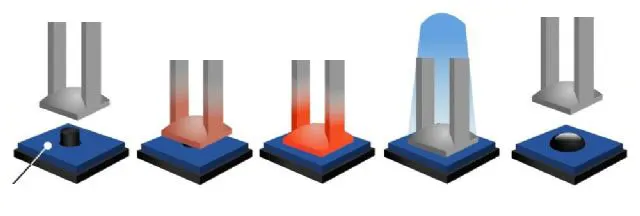
The plastic is deformed by heating it to a temperature above the glass transition temperature. For this Super-heated air or a thermode is used. Then the pressure is applied to create the stake. After formaation of the stake, the plastic should be cooled down again below the glass transition temperature. To ensure good fixation of the parts, cooling is performed under constant pressure . Compressed air can be applied for cooling when a thermode is used.
Heat staking can increase strength and quality, also be a low cost production option. It offers strength comparable to other operations involving secondary fasteners, and it doesn’t contaminate the finished product. Heat staking is highly reliabie,it offrs extreme durability, and corrosion resistance in harsh environments. Another benefit is that you don’t need to worry about eventual corrosion in the field due to dissimilar materials being used.
PROCEDURE :
STEP 1 : TOOLING AXIS CREATION
- To perform a Draft analysis the tooling cration is very mandatory. To create a tooling axis analize the best direction for it. In this perticular component the Y-direction is very convenient to create the tooling axis.
STEP 2 : DRAFT ANALYSIS ON CLASS-A SURFACE
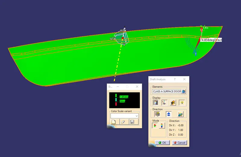
- To perform Draft Analysis go Insert-Analysis-Feature Draft Analysis.
- Then the Draft analysis Tool Bar is opend, select the Switch Bezel where we perform the draft analysis.
- Then set compass to the tooling axis by using Uses the Compass To Define the New Current Draft Direction.
- Then the lock the compass using Locks and Unlocks the draft direction. And move curser to part and select point and it shows the green color which represent the draft angle is 3 or above.
STEP 3 : CREATE B-SURFACE AND C-SURFACE
After draft analysis of class-A surface create class-B and class-C surface.
After complete the close profile use close surface command to add the material.
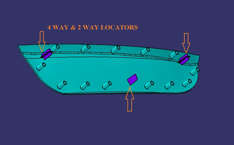
STEP 4 : CREATE 2-WAY AND 4-WAY LOCATOR
After close surface create the 2-way and 4-way locators on B-side.
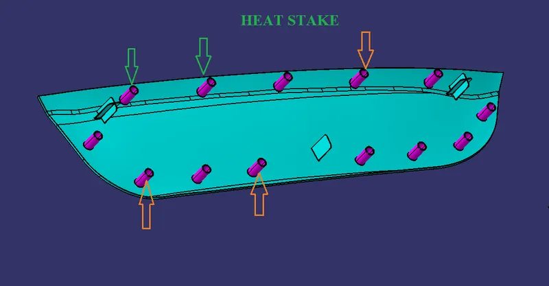
STEP 5 : CREATE HEAT STAKE
Also crerate a heat stake on B-side.
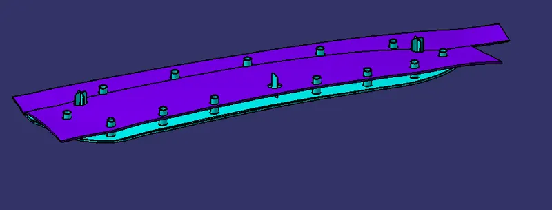
APPLIQUE
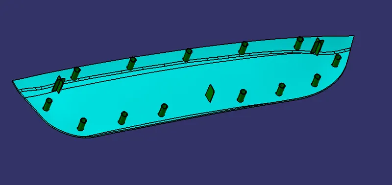
BASE
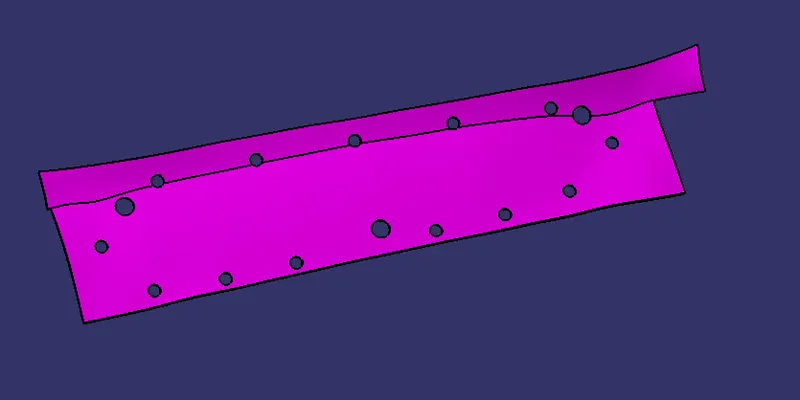
FINAL DOOR APLLIQUE
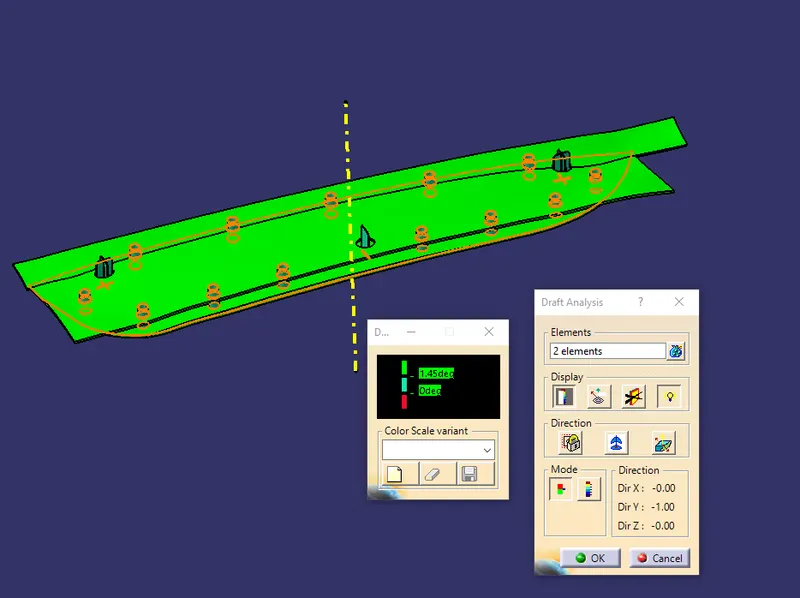
STEP 6 : DRAFT ANALYSIS OF FINAL COMPONENT
- To perform Draft Analysis go Insert-Analysis-Feature Draft Analysis.
- Then the Draft analysis Tool Bar is opend, select the Switch Bezel where we perform the draft analysis.
- Then set compass to the tooling axis by using Uses the Compass To Define the New Current Draft Direction.
- Then the lock the compass using Locks and Unlocks the draft direction. And move curser to part and select point and it shows the green color which represent the draft angle is 3 or above.
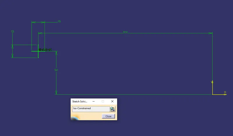
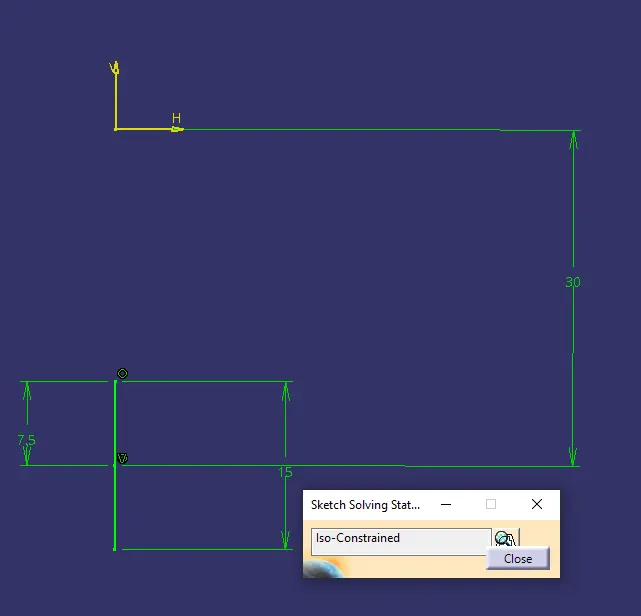
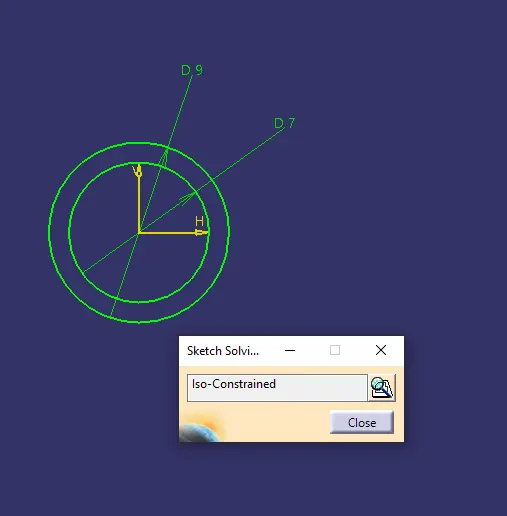
ISO-CONSTRAINED SKETCHES
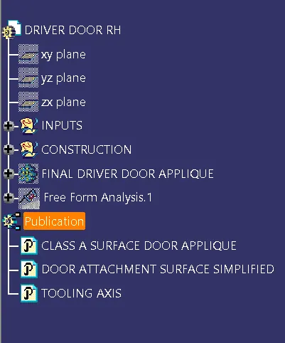
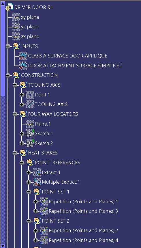
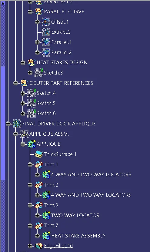
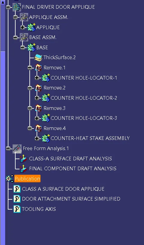
TREE STRUCTURE
CONCLUSION :
In this way we can design door applique design.