Automotive Door Trim Design and add Engineering Feature
AIM : TO CREATE AUTOMOTIVE DOOR TRIM PANEL AND ENGINEERING FEATURES.
OBJECTIVE :
- To perform Draft analysis on given Class-A surface.
- To create Class-B and Class-C surface to Create thicken body of Door Panel.
- To create engineering features like DogHouse, Push pin, Flanges, heat Stake, Locators, Ribs.
- To perform Draft analysis on the complete Dor Trim Panel.
INTRODUCTION:
DOOR TRIM PANEL:
It is an interior plastic part having engineering atachment features to engage with exterior sheet metal Door panel. In this poject we have a Class-A surface of door trim panel, which includes Map pocket, Lower Substrate, Bottle Holder, and Arm Rest. So my first moto is that to perform a Draft analysis on every Class-A surface to check its Draft angle. After that create Class-B and Class-C for creating complete close body. After creating thicken part create Attachment features like DogHouse, Push Pin, Flanges, Heat Stake, Locators, and Ribs.
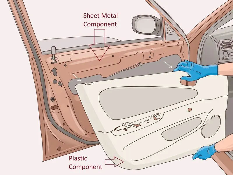
ENGINNERING ATTACHMENT FEATURES:
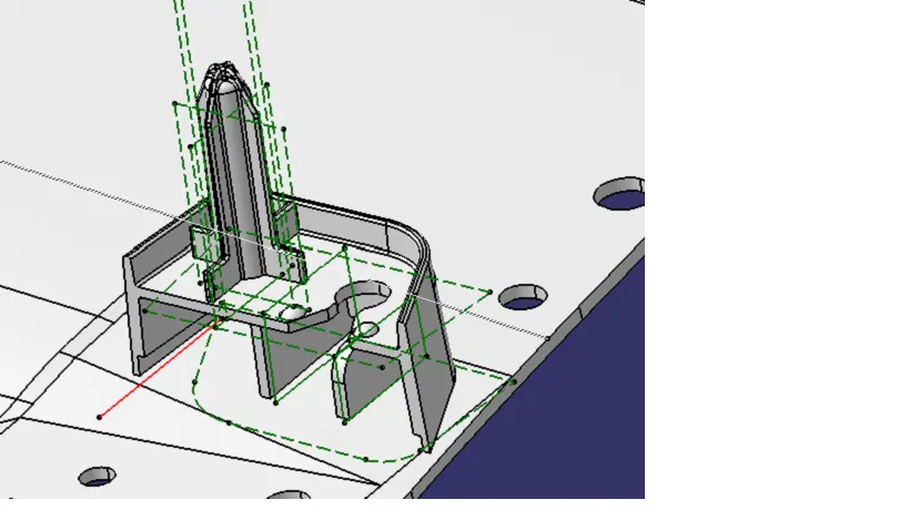
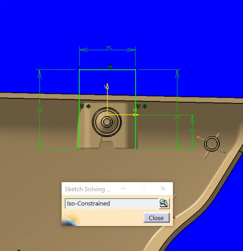
DOG HOUSE :
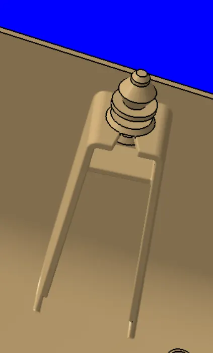
- Dog house is an engineering feature used in plastic trim design.
- Dog houses are used as supporting feature. Sometimes other engineering features like snaps, locators etc. are mounded on them to increase their strength.
- Dog houses are subjected to draft analysis to prevent breakage of the component during ejection from mould cavity.
- Dog house and other engineering components are built on B-surface.
- GENERAL GUIDELINES FOR BOSSES :
- Draft - 0.5 degrees on walls of boss
- Thickness - Typically 40%* of the nominal wall at the base.
- Height to Diameter Ratio - 3:1
- Radii - 0.25mm maximum radii.
- GENERAL GUIDELINE FOR DOG HOUSE :
-
Doghouse wall thickness at the intersection of the part wall ( C ) should be 40% or less than the main wall stock ( T ).
-
Height of ( B ) should be between 3.0 – 6.0 mm
PUSH PIN:
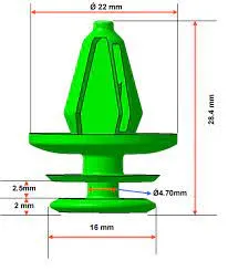
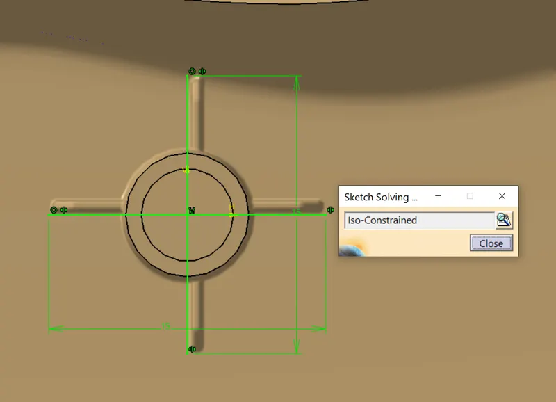
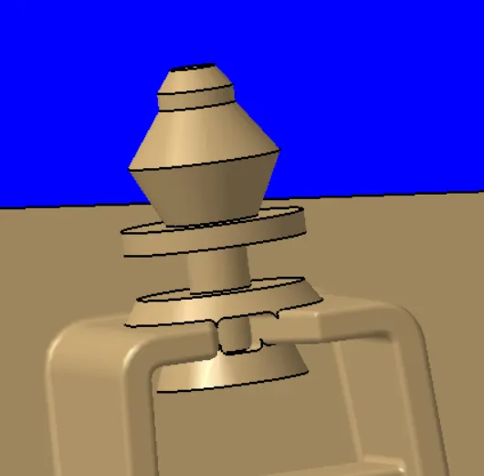
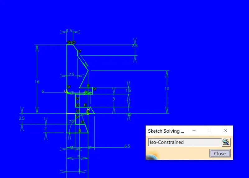
- Push Pins, also known as dart type fasteners, are versatile in design for a wide range of applications.
- When light retention is required, plastic Push Pins can be used as hole plugs, bearings or spacers.
- They are well-suited for simplified assembly or products knocked down for consumer assembly.
HEAT STAKE:
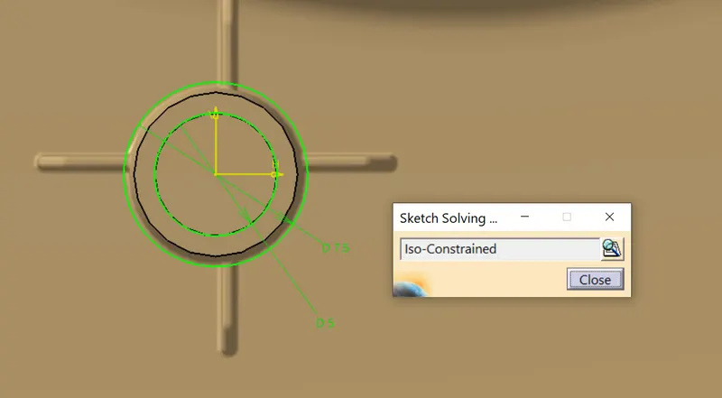
In manufacturing products with thermoplastic components, it is often necessary to join a thermoplastic to a part of dissimilar material, whether it be metal, a dissimilar plastic, or other material. This process is known as Heat Staking.
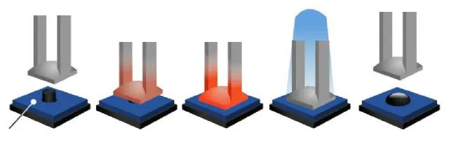
The plastic is deformed by heating it to a temperature above the glass transition temperature. For this Super-heated air or a thermode is used. Then the pressure is applied to create the stake. After formaation of the stake, the plastic should be cooled down again below the glass transition temperature. To ensure good fixation of the parts, cooling is performed under constant pressure . Compressed air can be applied for cooling when a thermode is used.
Heat staking can increase strength and quality, also be a low cost production option. It offers strength comparable to other operations involving secondary fasteners, and it doesn’t contaminate the finished product. Heat staking is highly reliabie,it offrs extreme durability, and corrosion resistance in harsh environments. Another benefit is that you don’t need to worry about eventual corrosion in the field due to dissimilar materials being used.
RIBS:
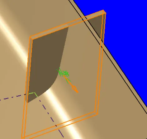
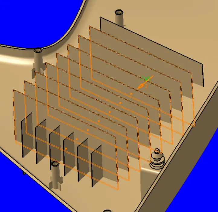
- Ribs are a feature in plastic injection molded parts. They are thin extensions that run perpendicular from a wall or plane. They are commonly used to provide additional support and strength to a part. Thickness and location are essential to rib design.
GUIDELINES FOR RIBS ON SURFACE
- RIB THICKNESS
- Ribs should be designed to be 50-60 percent of the nominal wall thickness. Thinner does not provide much structure and may be hard to fill. Thicker ribs are tempting, but they can begin to introduce sinks on the cosmetic surface.
- RIB HIEGHT
- For maximum effectiveness, rib height should be no more than three times the nominal wall thickness. Since the rib will be thinner than the wall, it may be hard to fill it if it is taller.
- RIB SPACING
- Increase the number of ribs rather than their height in order to increase stiffness. Ribs should be spaced a minimum of two times the nominal wall thickness apart from one another.
- RIB DRAFT
- A minimum 0.5 degree draft will ensure that they release from the tool during molding.
- RIB CORING
- Core thick ribs from the back or below to create a blank area and thinner rib walls. This will help mitigate cosmetic sinks.
- RIB RADII
- Radii at feature intersections should be a minimum of 0.5 - 1.0x nominal wall thickness to increase rib strength.
MASTER SECTION
Master sections are the guides for design requirements which decide the component packaging after technical (Styling, Concept or Class-A) surfaces.
PROCEDURE:
CLASS-A SURFACE
Class A surface refers to those surfaces which are VISIBLE and abide to the physical meaning, in a product. This classification is primarily used in the automotive and increasingly in consumer goods
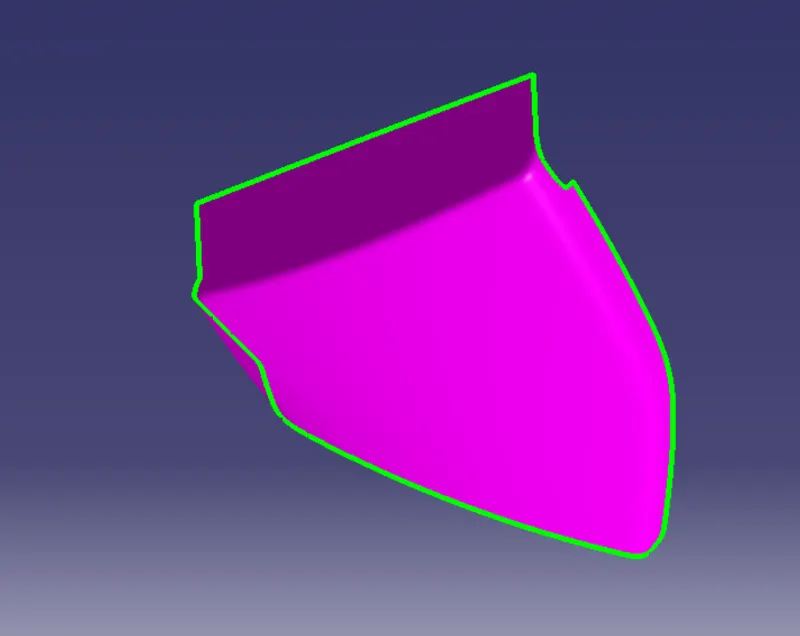
- MAP POCKET
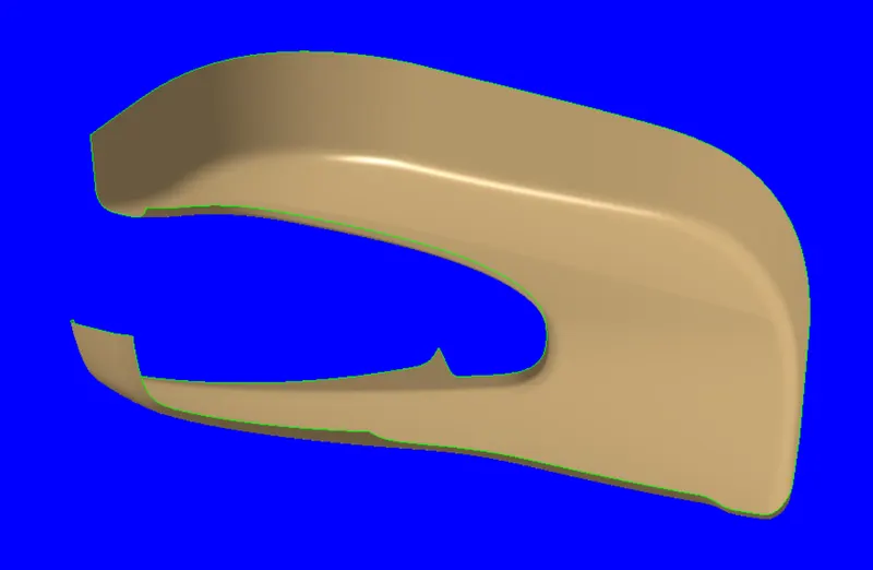
- LOWER SUBSTRATE
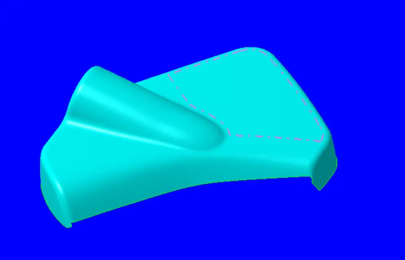
- BOTTLE HOLDER
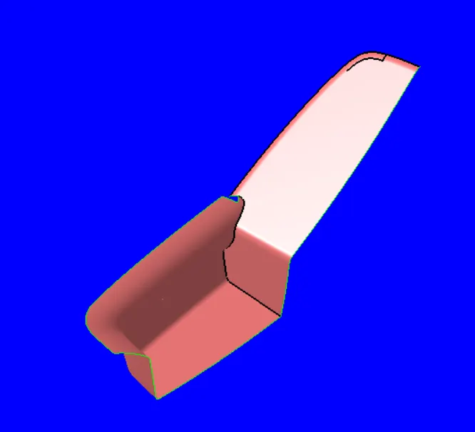
- ARM REST
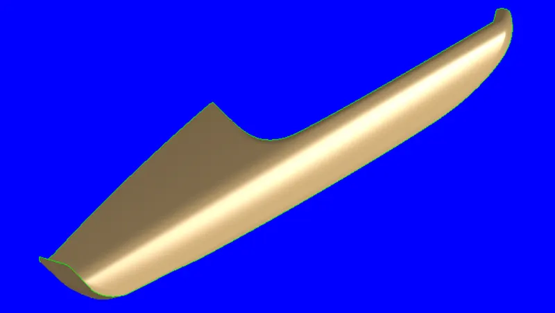
STEP 1 : TOOLING AXIS CREATION
- To perform a Draft analysis the tooling cration is very mandatory. To create a tooling axis analize the best direction for it.
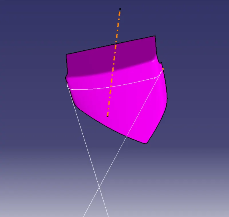
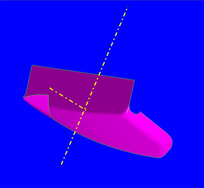
- MAP POCKET
There are two tooing axis for the Map pocket one is Main tooling axis and another is Sider Axis to clear DogHouse inside draft analysis.
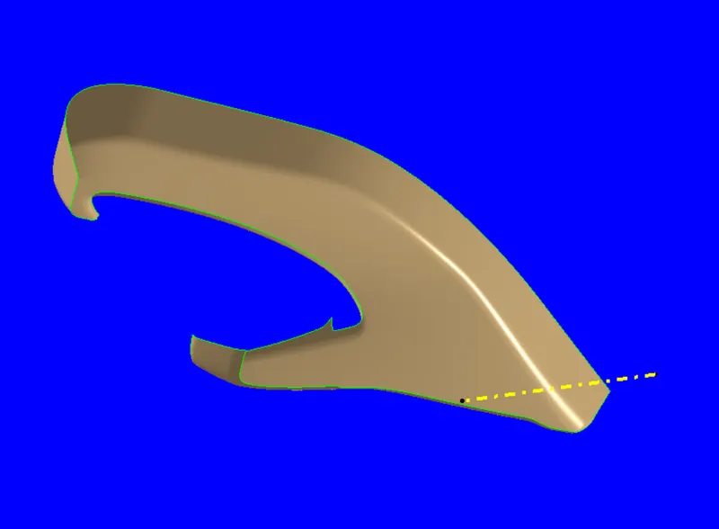
- LOWER SUBSTRATE
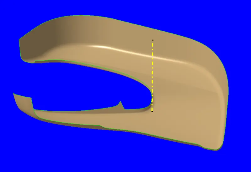
There are two tooing axis for the Lower Substrate one is Main tooling axis and another is Sider Axis to clear DogHouse inside draft analysis.
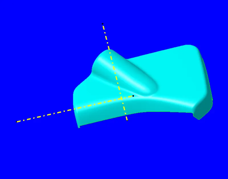
- BOTTLE HOLDER
There are two tooing axis for the Bottle Holder one is Main tooling axis and another is Sider Axis to clear draft analysis.
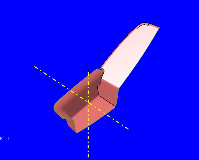
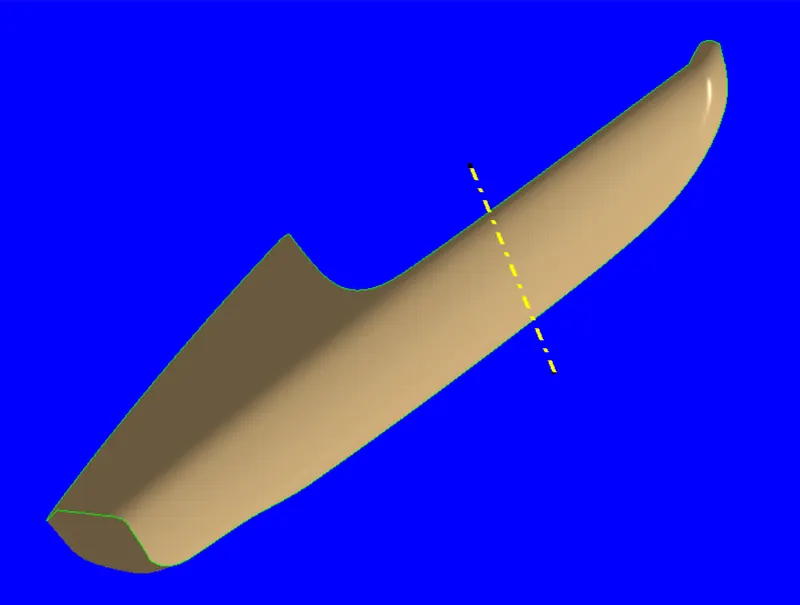
- ARM REST
There are two tooing axis for the Bottle Holder one is Main tooling axis and another is Sider Axis to clear draft analysis.
STEP 2 : DRAFT ANALYSIS ON CLASS-A SURFACE
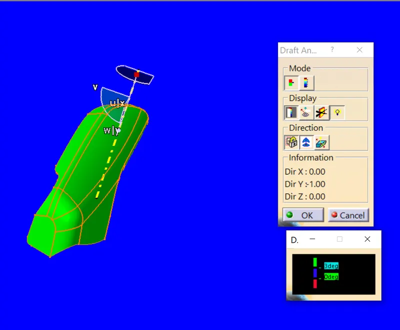
- To perform Draft Analysis go Insert-Analysis-Feature Draft Analysis.
- Then the Draft analysis Tool Bar is opend, select the Switch Bezel where we perform the draft analysis.
- Then set compass to the tooling axis by using Uses the Compass To Define the New Current Draft Direction.
- Then the lock the compass using Locks and Unlocks the draft direction. And move curser to part and select point and it shows the green color which represent the draft angle is 3 or above.
- MAP POCKET
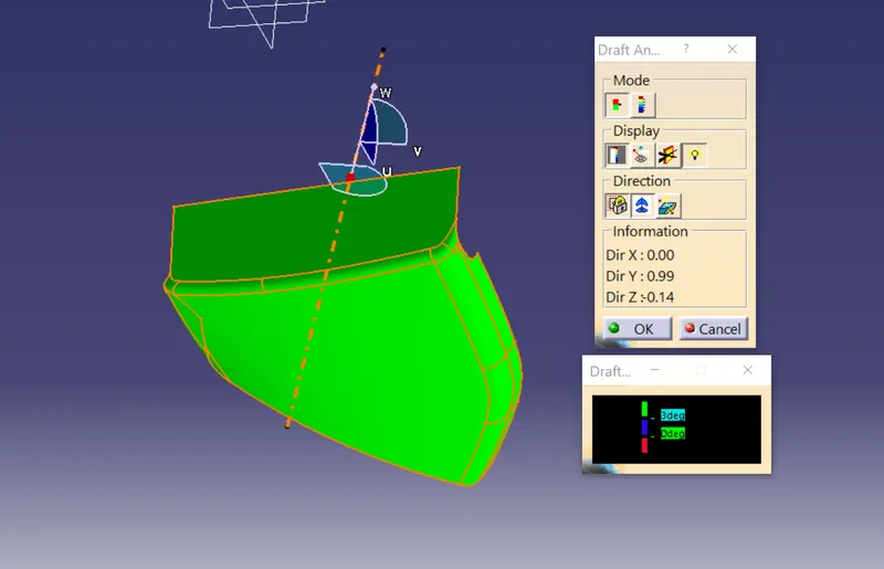
- LOWER SUBSTRATE
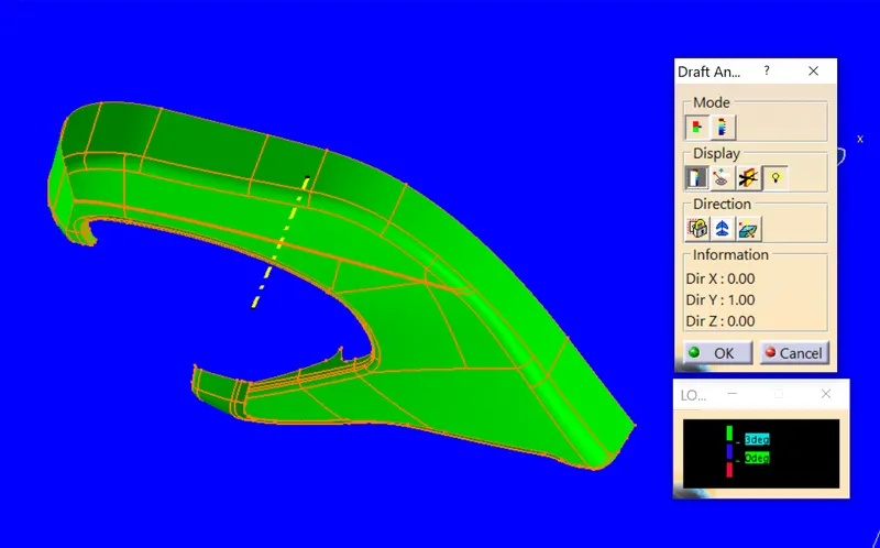
- BOTTLE HOLDER
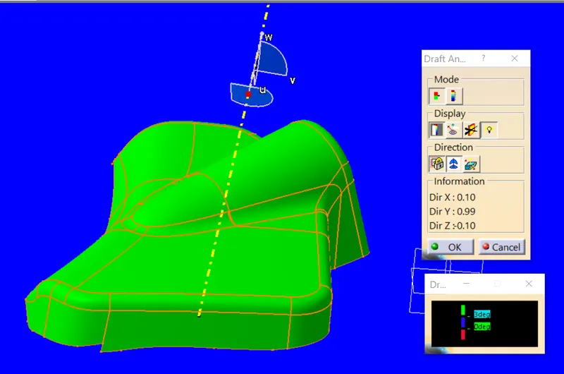
- ARM REST
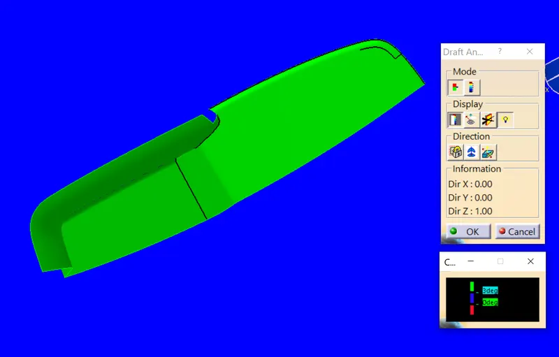
STEP 3 : CLASS-B SURFACE CREATION
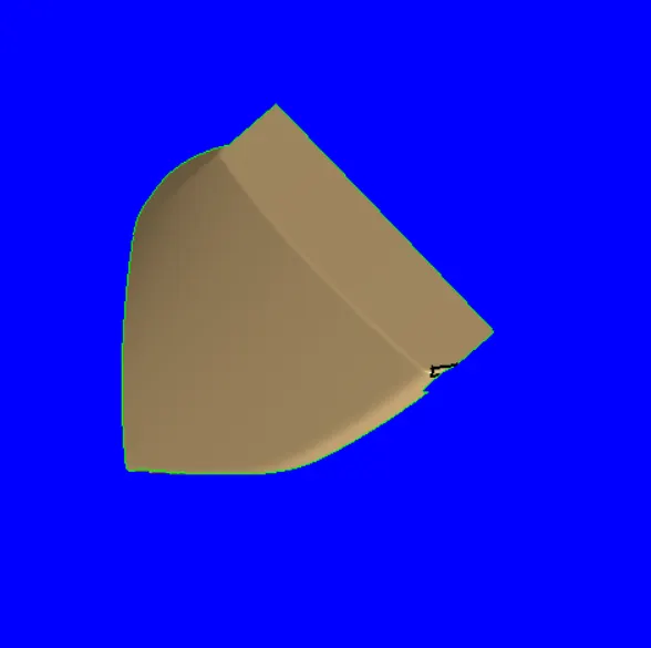
- From given Class-A surface create a Class-B surface of an offset of 2.5 mm as a given thickness.
- To create a Class-B surface we have to extract all the boundary of improved Class-A.
- Then provide an offset of 2.5 mm.
- MAP POCKET
- LOWER SUBSTRATE
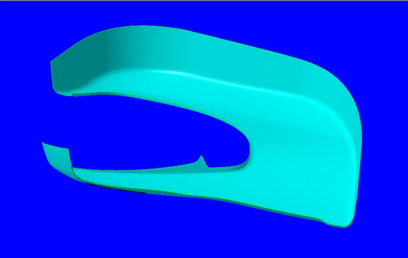
- BOTTLE HOLDER
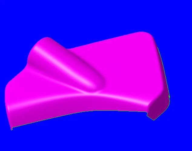
- ARM REST
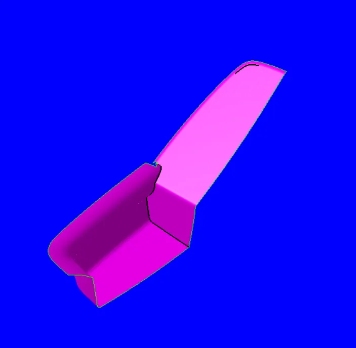

STEP 4 : CLASS-C SURFACE CREATION
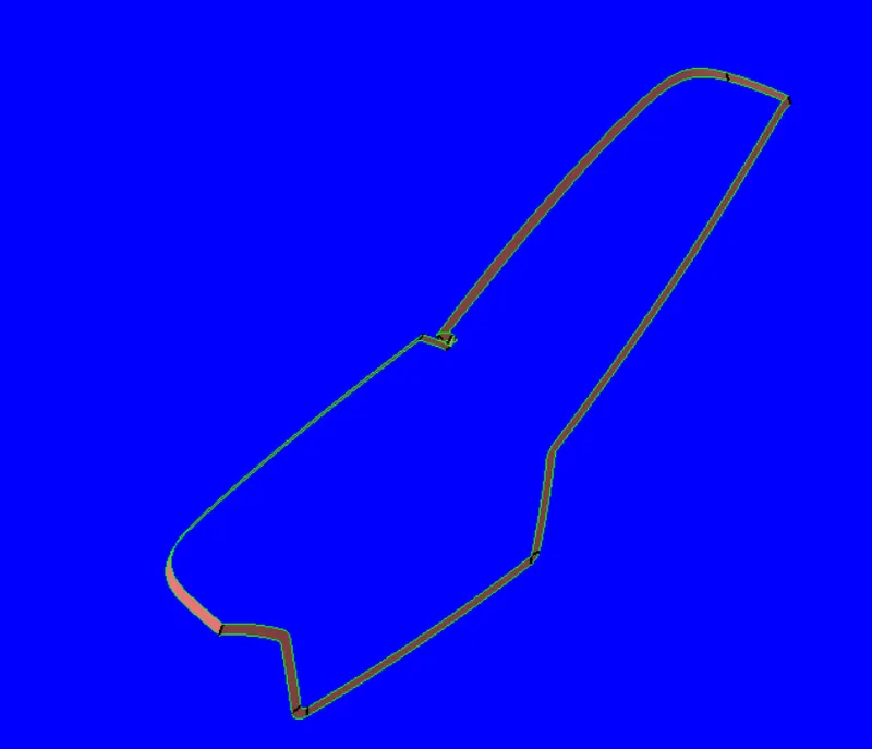
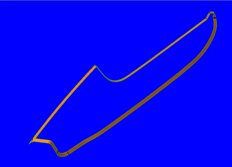
- To join Class-A and Class-B surfaces we have to create a Class-C surface.
- To create a Class-C surface we have to extract the boundries of the Class-A surface.
- After that use the sweep command to sweep the boundries along with tooling axis as an second guide curve.
- There will some minor gap between Class-a and Class-C surface due to draft angle.
- To overcome this problem extrapolate the class-A and Class-C surface and trim it.
- After that join the Class-A and Class-C surface using the join command.
- MAP POCKET
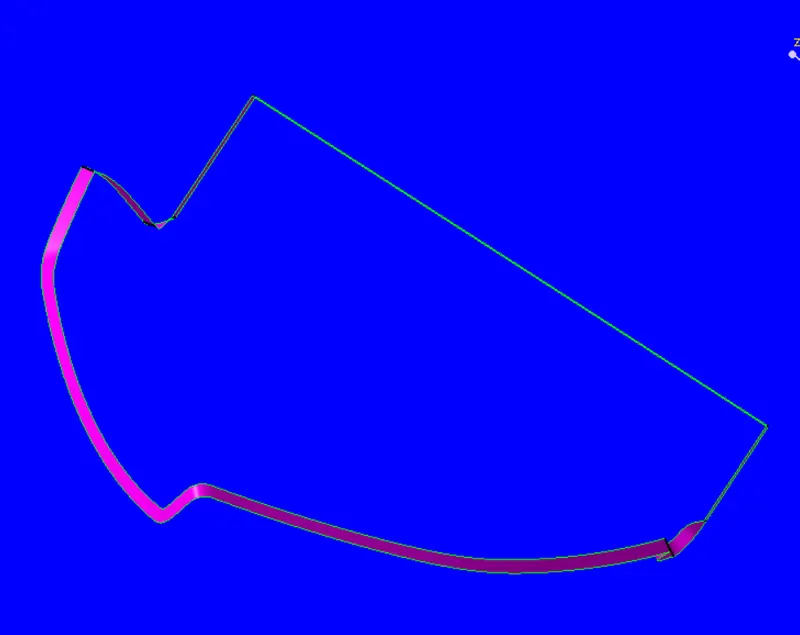
- LOWER SUBSTRATE
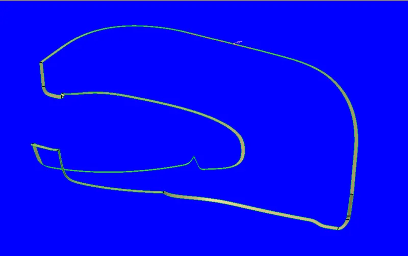
- BOTTLE HOLDER
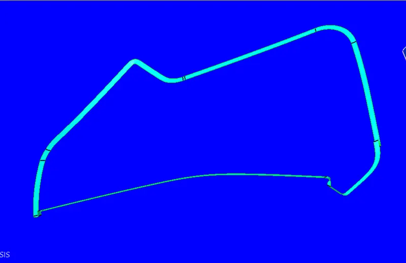
- ARM REST
STEP 5 : CLOSE SURFACE CREATION
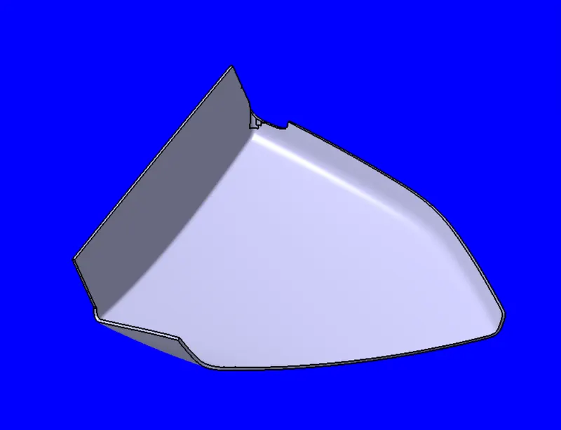
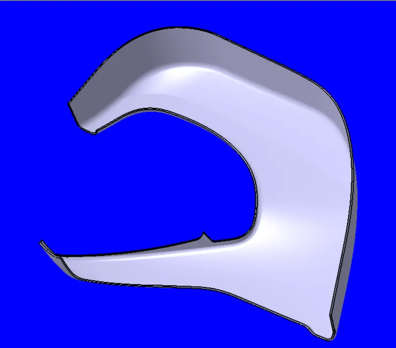
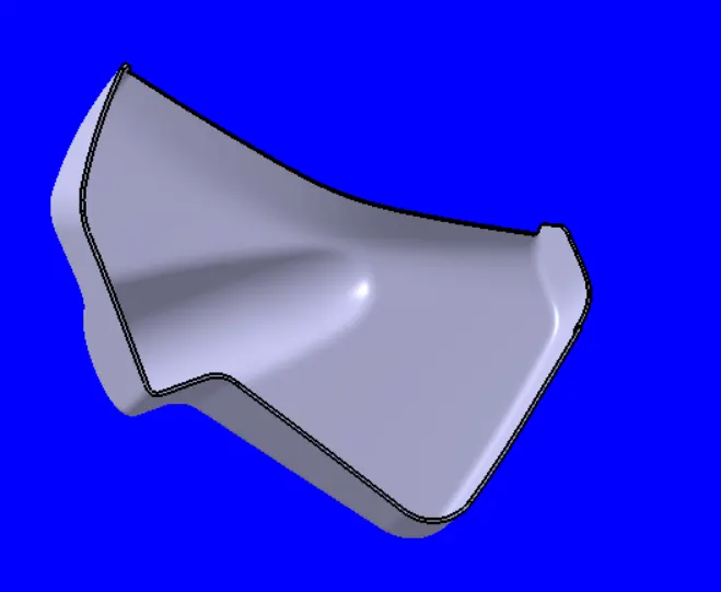
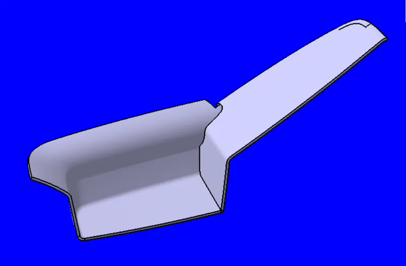
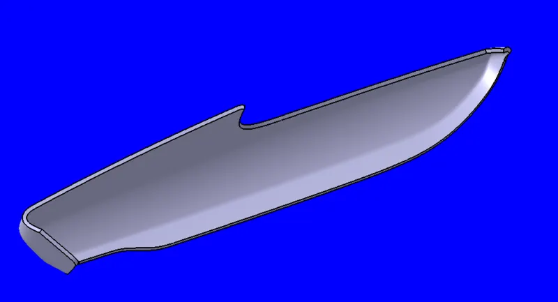
- To create complete close surface trim the Join of Class-A nad Class-C from the Class-B surface to get desired close surface.
- After that go to Part Workbench use Close Surface command to get thicken part.
- MAP POCKET
- LOWER SUBSRATE
- BOTTLE HOLDER
- ARM REST
STEP 6 : CREATE DOG HOUSE WITH LOCATORS
STEP 7 :
CREATE RIBS
HEAT STAKE AND LOCATORS
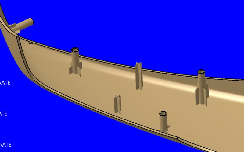
SUPPORTING RIBS HEAT STAKE
PUSH PIN
STEP 8 : DRAFT ANALYSIS ON CLOSE SURFACE
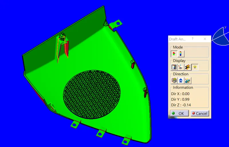
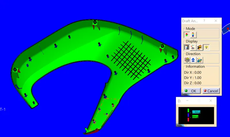
- To perform Draft Analysis go Insert-Analysis-Feature Draft Analysis.
- Then the Draft analysis Tool Bar is opend, select the Switch Bezel where we perform the draft analysis.
- Then set compass to the tooling axis by using Uses the Compass To Define the New Current Draft Direction.
- Then the lock the compass using Locks and Unlocks the draft direction. And move curser to part and select point and it shows the green color which represent the draft angle is 0.5 or above.
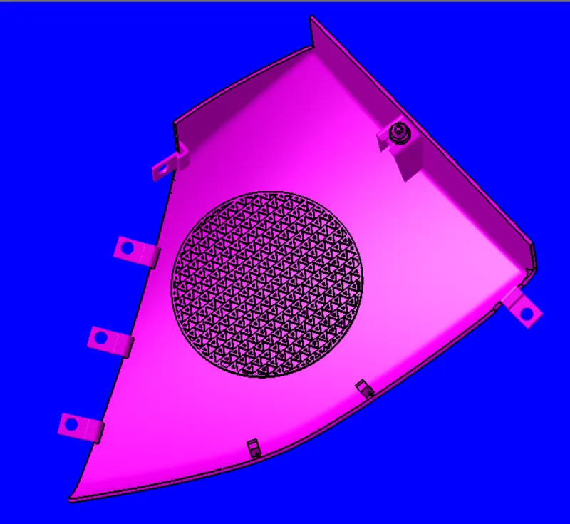
- MAP POCKET
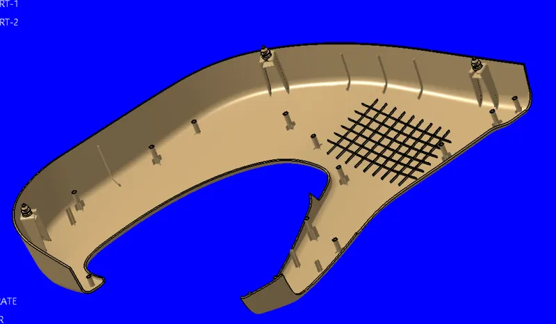
- LOWER SUBSRATE
- BOTTLE HOLDER
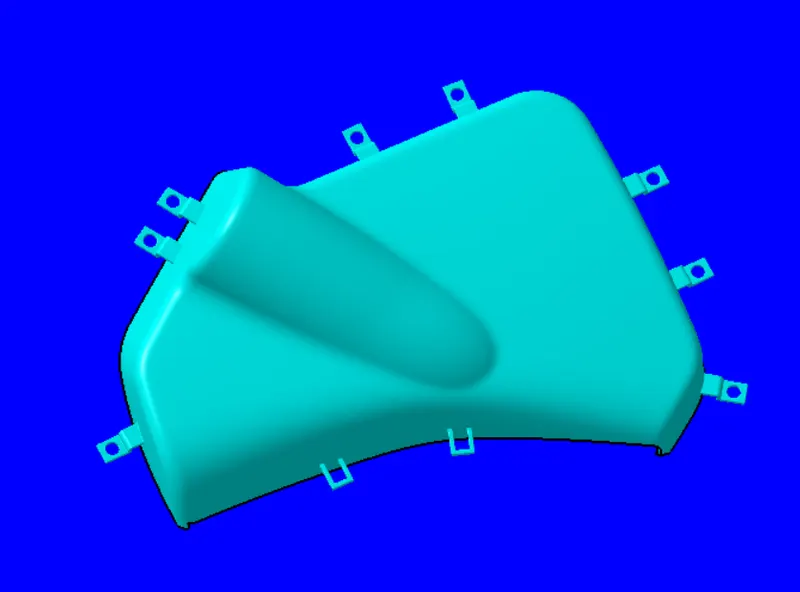
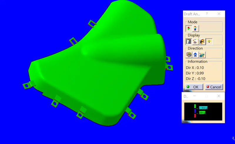
- ARM REST
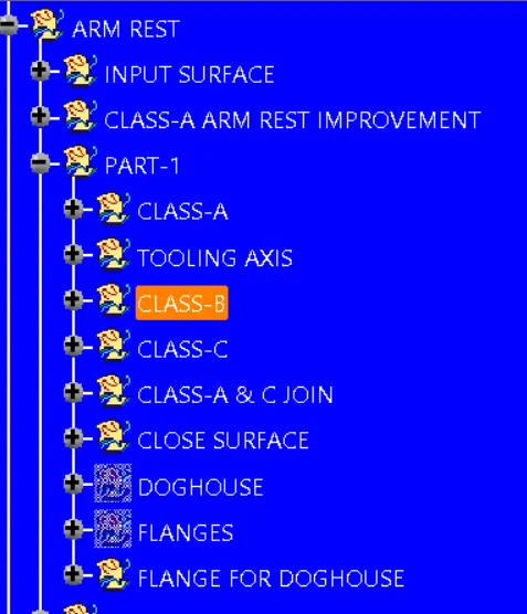
PART-1
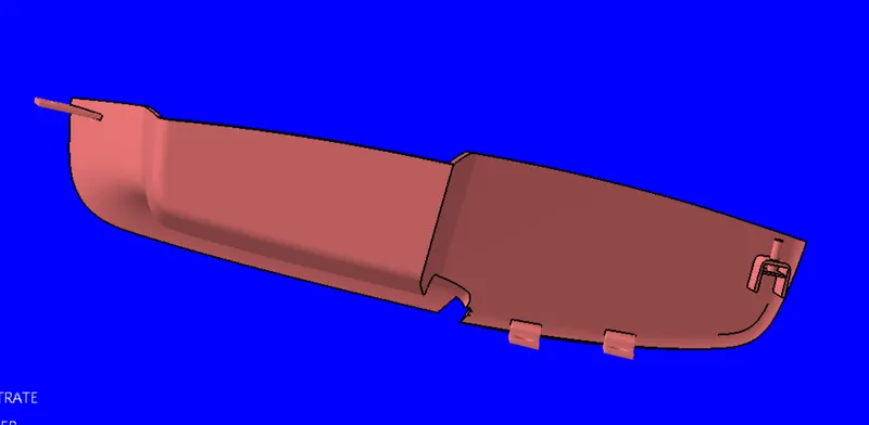
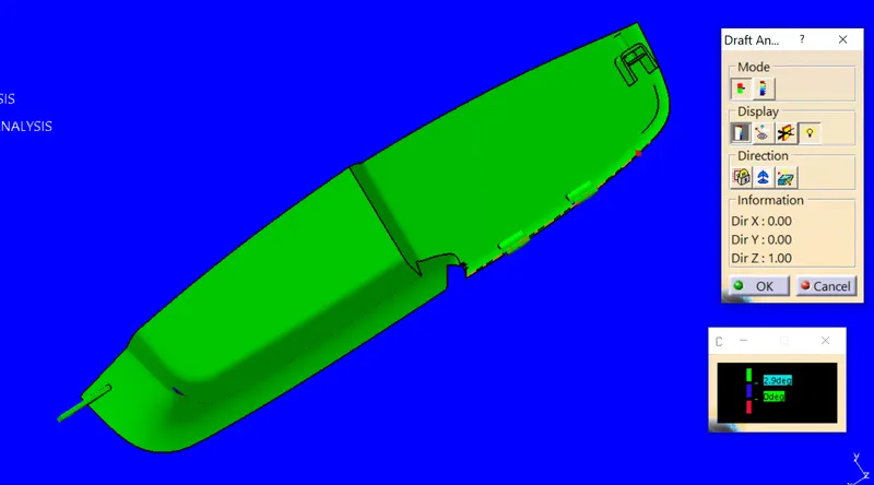
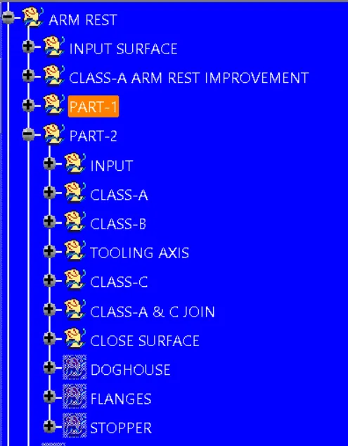
PART-2
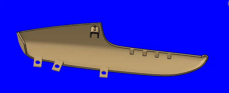
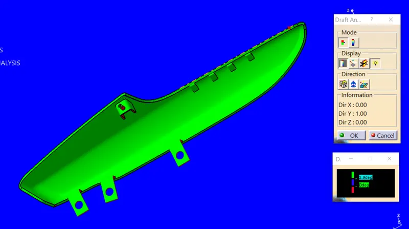
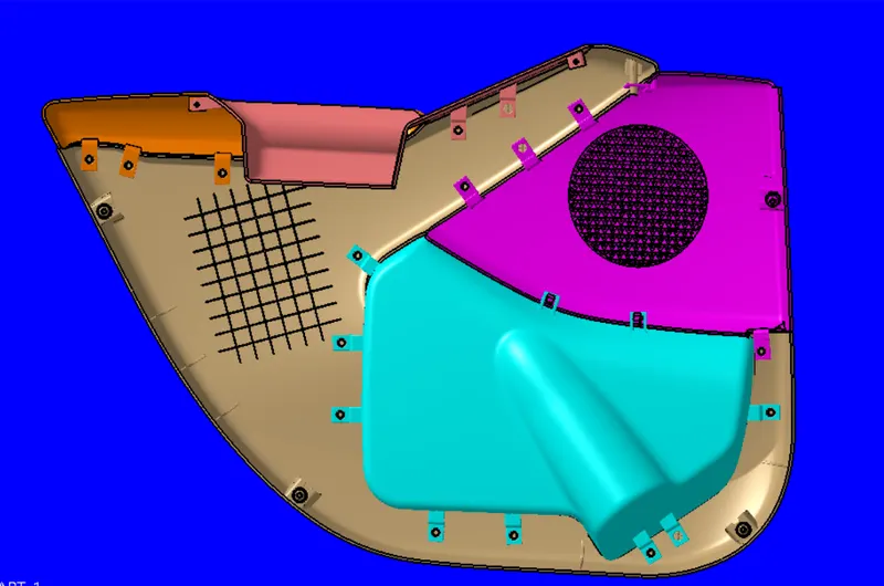
FINAL DOOR TRIM PANEL WITH ENGINEERING ATTACHEMENT FEATURE
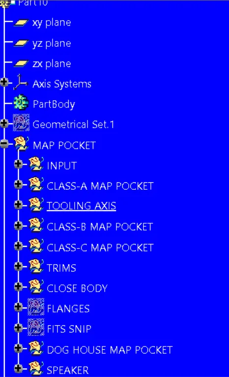
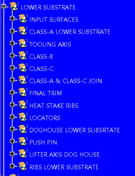
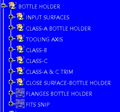
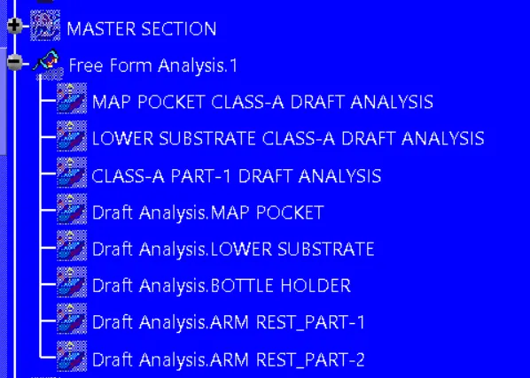
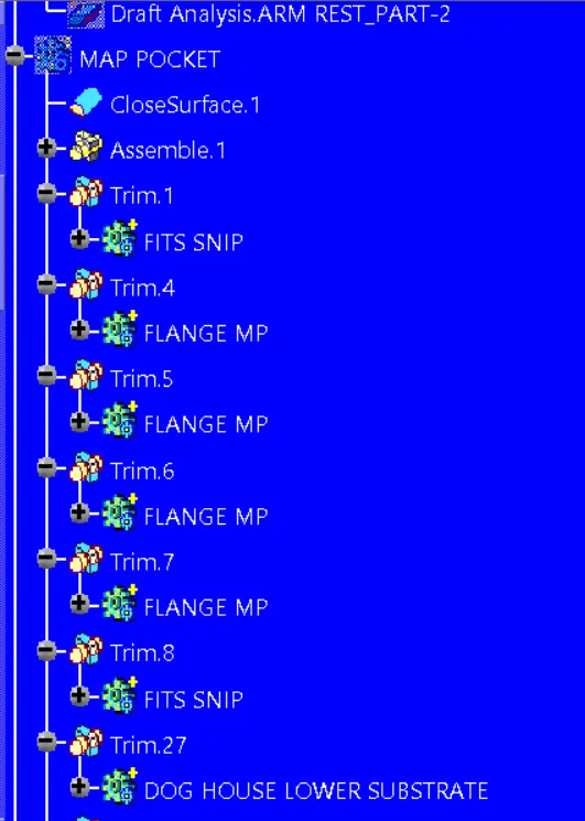
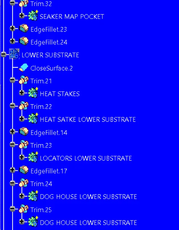
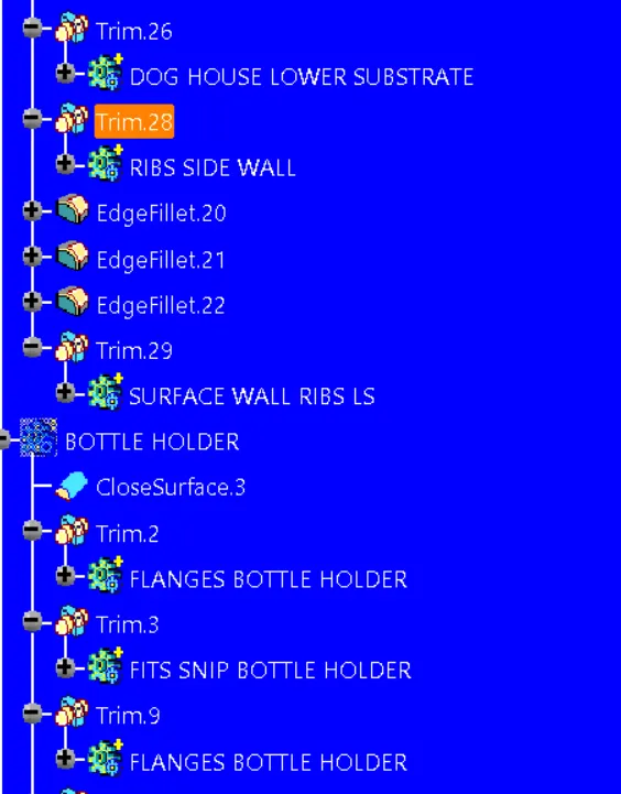
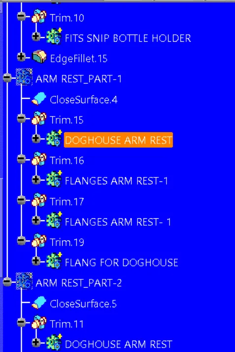
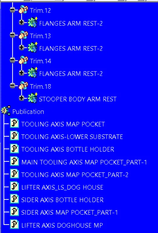
TREE STRUCTURE :
CONCLUSION:
In this way, with proper design guideline we create a Automotive Door Trim Panel using CATIA V5.