Week 8 - Challenge 4 - Coin Holder Design
AIM : To create a Coin Holder Plastic component through the given Class-A surface. Perform the Draft analysis on the model.
DRAFT ANALYSIS:
When creating Plastic component in core and cavity it is very difficult to eject part from tool of an angle of 90 degree. A small draft angle provide to each area of the part in order to easy removal of the component from the tool.
PROCEDURE:
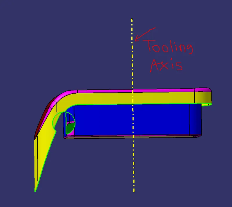
STEP 1 : TOOLING AXIS CREATION
To perform a Draft analysis the tooling cration is very mandatory. To create a tooling axis analize the best direction for it. In this perticular component the Y-direction is very convenient to create the tooling axis.
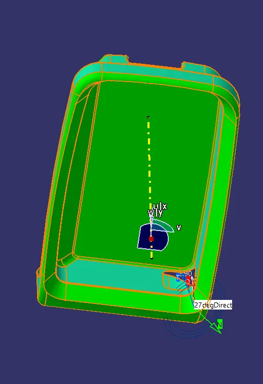
STEP 2 : DRAFT ANALYSIS ON CLASS-A SURFACE
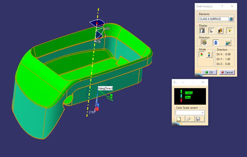
To perform Draft Analysis go Insert-Analysis-Feature Draft Analysis.
Then the Draft analysis Tool Bar is opend, select the Switch Bezel where we perform the draft analysis.
Then set compass to the tooling axis by using Uses the Compass To Define the New Current Draft Direction.
Then the lock the compass using Locks and Unlocks the draft direction. And move curser to part and select point and it shows the green color which represent the draft angle is 3 or above.
STEP 3 : CLASS-B SURFACE CREATION
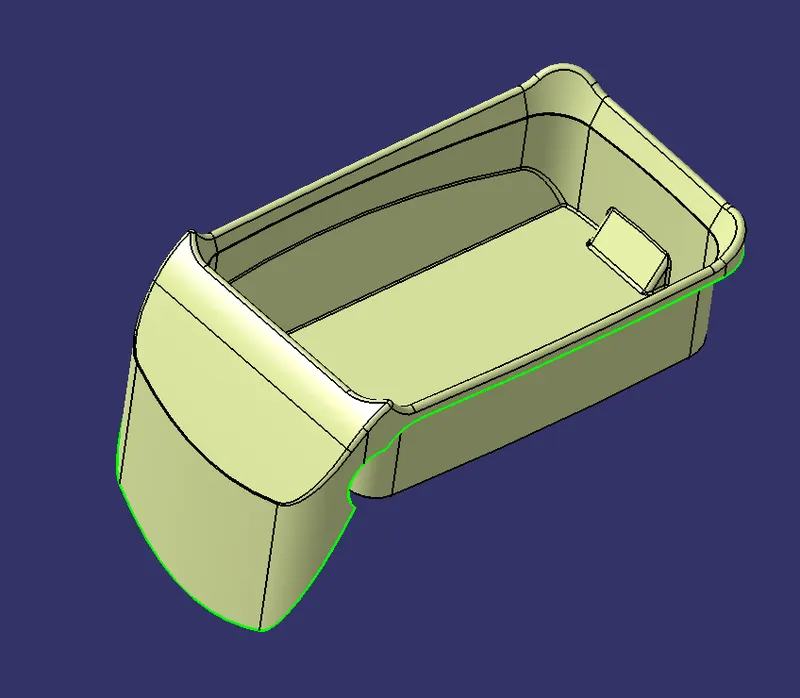
- From given Class-A surface create a Class-B surface of an offset of 2.5 mm as a given thickness.
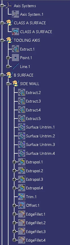
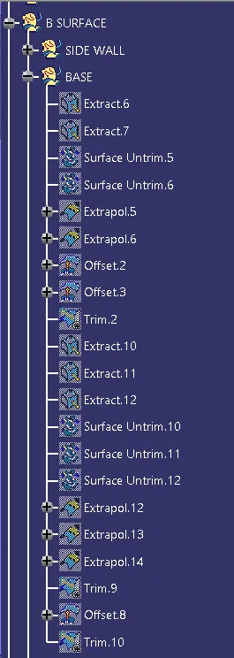
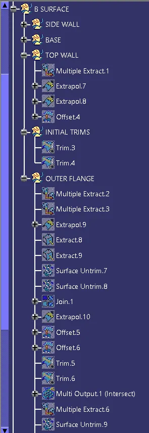
- To create a Class-B surface we have to extact all the wall and then untrim it.
- After untrim the walls extrapolate then at 30 mm distance to perform further operation on it.
- Then provide an offset of 2.5 mm to untrim walls.
- Then trim the walls to get an desired shape for the component.
- Then use the Fillet to edges of internal wall.
STEP 4 : CLASS-C SURFACE CREATION
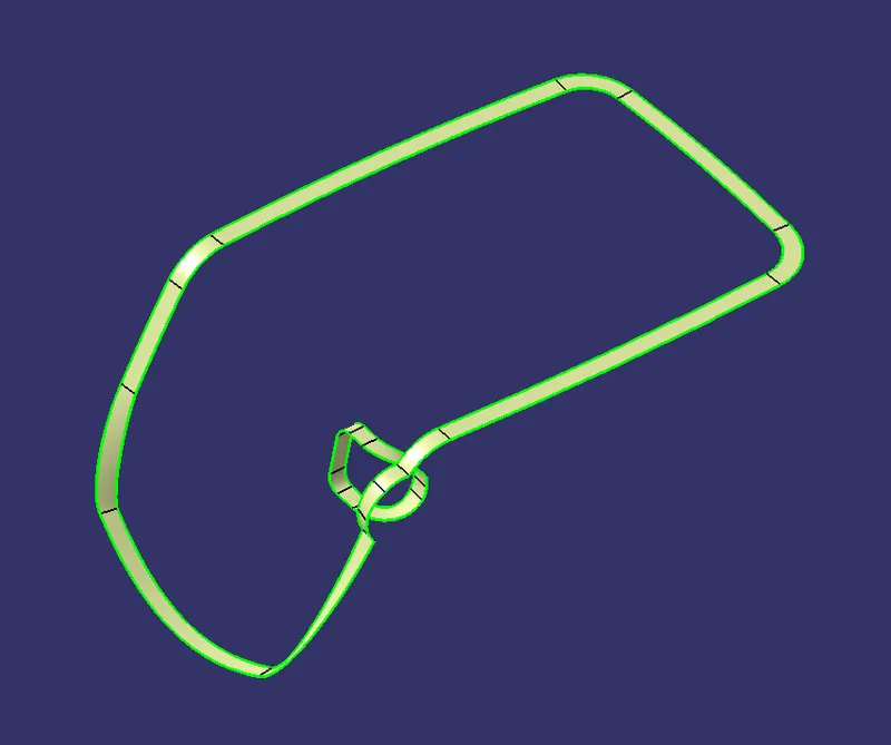
- To join Class-A and Class-B surfaces we have to create a Class-C surface.
- To create a Class-C surface we have to extact the boundries of the Class-A surface.
- After that use the sweep command to sweep the boundries along with tooling axis as an second guide curve.
- There will some minor gap between Class-a and Class-C surface due to draft angle.
- To overcome this problem extrapolate the class-A and Class-C surface and trim it.
- After that join the Class-A and Class-C surface using the join command.
STEP 5 : CLOSE SURFACE CREATION
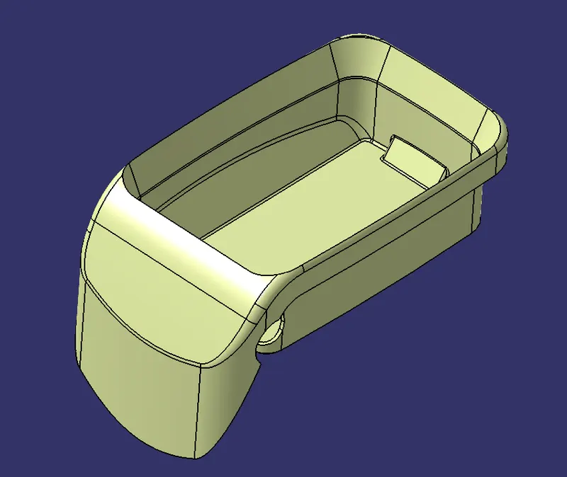
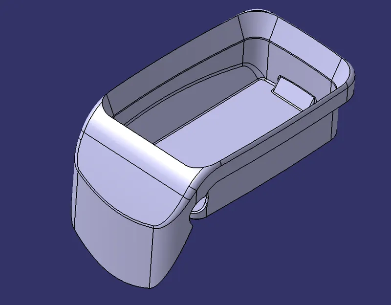
To create complete close surface trim the Join of Class-A nad Class-C from the Class-B surface to get desired close surface.
After that go to Part Workbench use Close Surface command to get thicken part.
STEP 6 : DRAFT ANALYSIS ON CLOSE SURFACE
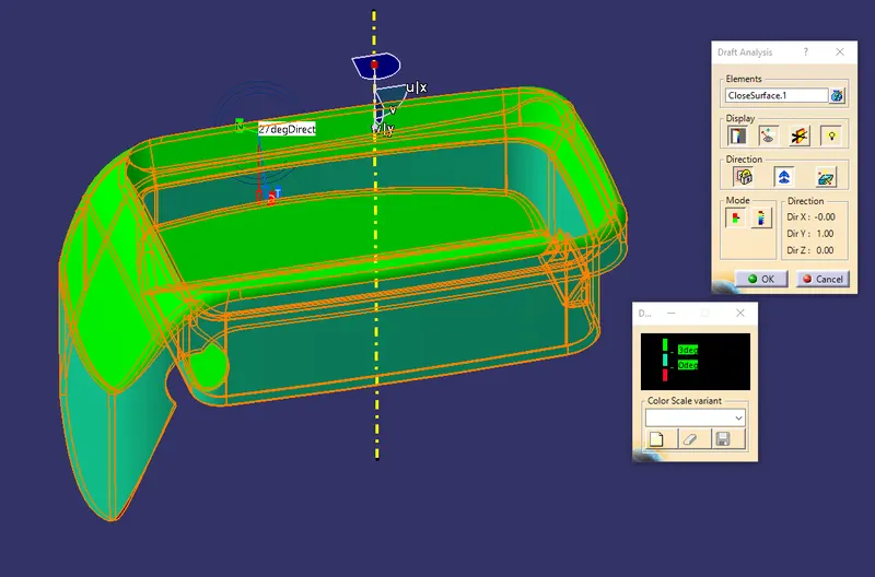
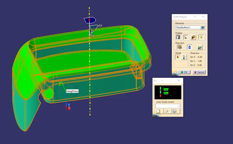
To perform Draft Analysis go Insert-Analysis-Feature Draft Analysis.
Then the Draft analysis Tool Bar is opend, select the Switch Bezel where we perform the draft analysis.
Then set compass to the tooling axis by using Uses the Compass To Define the New Current Draft Direction.
Then the lock the compass using Locks and Unlocks the draft direction. And move curser to part and select point and it shows the green color which represent the draft angle is 3 or above.
ISOMETRIC VIEW
CLOSE SURFACE
FRONT SIDE VIEW
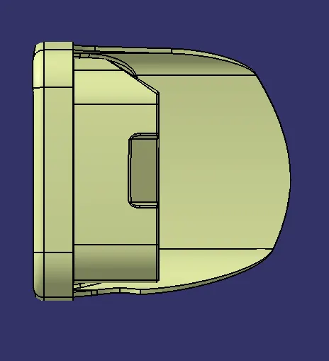
BACK SIDE VIEW
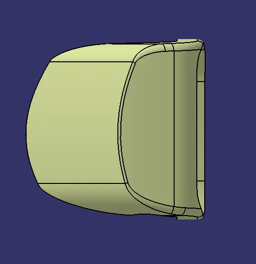
LEFT HAND SIDE VIEW
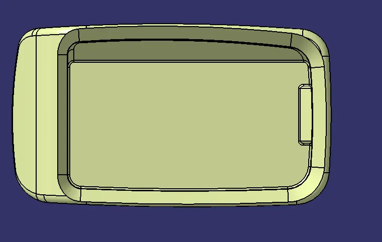
RIGHT HAND SIDE VIEW
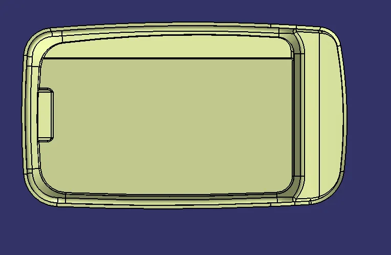
TOP SIDE VIEW
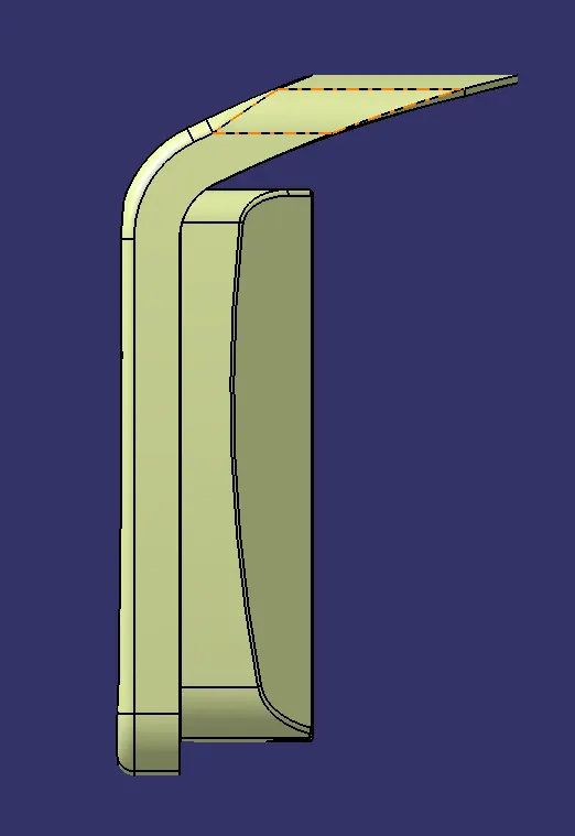
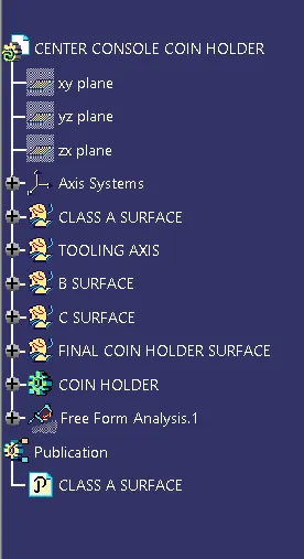
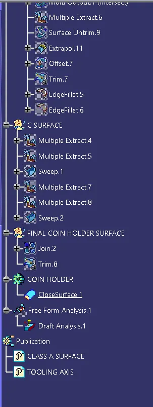
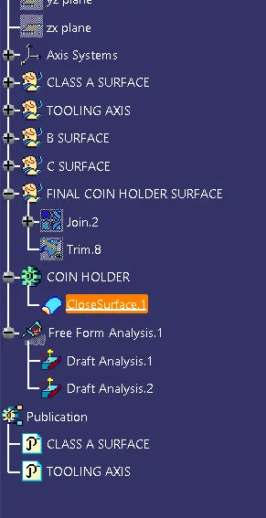
TREE STRUCTURE