Week - 4
Aim:
- Implement control logic of a 'washing machine' using Stateflow as per the given sequence.
- Make a Simulink chart for the 'Gear shift' logic.
Theory:
State Flow:
- Stateflow is a technique to convert a flow chart or logic into a systematical arrangement.
- Stateflow provides a graphical language that includes state transition diagrams, flow charts, state transition tables, and truth tables. You can use Stateflow to describe how MATLAB algorithms and Simulink models react to input signals, events, and time-based conditions.
- Stateflow enables you to design and develop supervisory control, task scheduling, fault management, communication protocols, user interfaces, and hybrid systems.
- With Stateflow, you model combinatorial and sequential decision logic that can be simulated as a block within a Simulink model or executed as an object in MATLAB. Graphical animation enables you to analyze and debug your logic while it is executing. Edit-time and run-time checks ensure design consistency and completeness before implementation.
Flow-Chart:
- A Stateflow flow chart is a graphical construct that models logic patterns such as decision trees and iterative loops.
- Flow charts represent combinatorial logic in which one result does not depend on prior results.
- You build flow charts by combining connective junctions and transitions without using any states.
- The junctions provide decision branches between different transition paths. Executing a flow chart begins at a default transition and ends at a terminating junction (a junction that has no valid outgoing transitions).
#Part_1:
Objective:
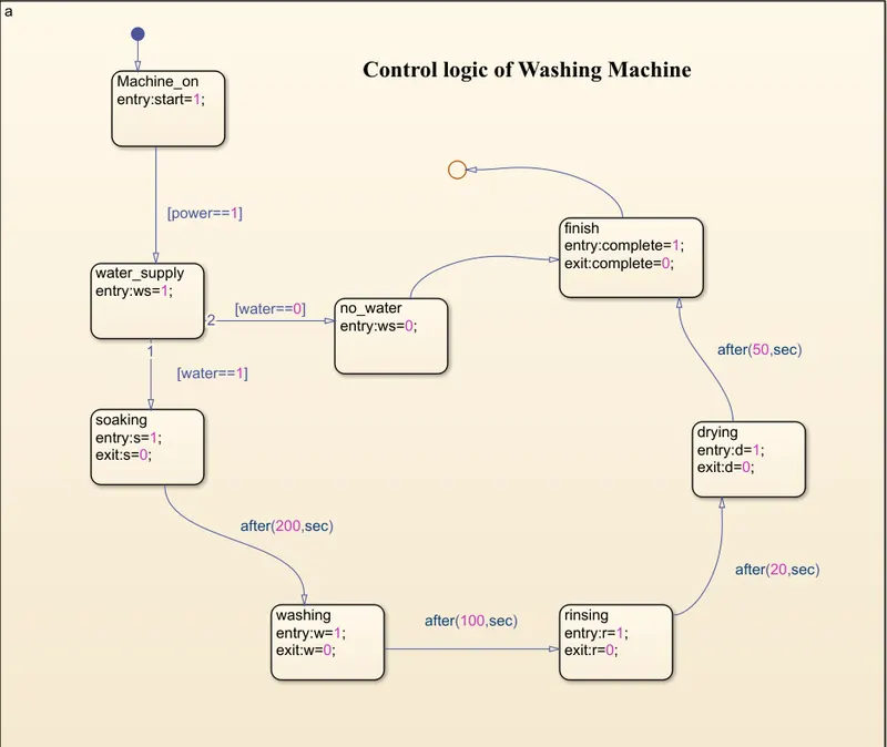
Use control logic of a 'Washing Machine' as per given sequence,
- If the power supply is available, the system gets activated.
- If the Water supply is not available, stop the process & indicate through the LED.
- Soaking time should be 200s followed by Washing time of 100s.
- Then rinsing happens for the next 20s & dryer runs for 50s.
- After all the processes have completed turn on the finished LED
Simulink Flow-Chart:
Control logic Washing Machine:
Symbol Pane:
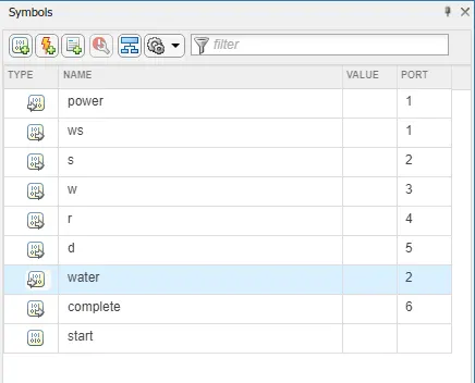
- In the Symbols pane, you can view and manage data, events, and messages while working in the Stateflow editor.
Procedure:
- So first, we build the logic of the Washing Machine in the flow chart.
- Define the blocks for each condition i.e. giving power supply and water supply to the complete process.
- Following is the step by step explanation of blocks
- The first block gives a power supply to the system, with the condition 'power==1'.
- The second block gives a water supply to the Machine, there are two conditions, i) 'water==1', If this condition satisfied water is supply to the machine and further function is done, or ii)'water==0', If this condition is satisfied then Machine is getting stop without doing any function.
- Then for a 200-sec machine do the Soaking.
- Then for the next 100-sec Washing is done.
- After that rinsing is done for 20 sec.
- Then for the next 50-sec drying is done.
- After that machine finishes the process.
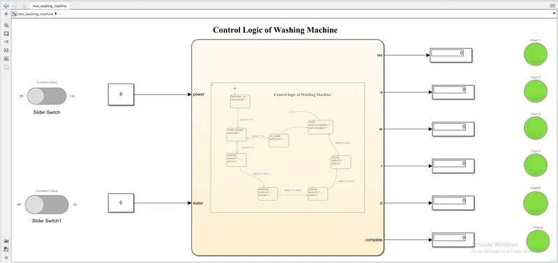
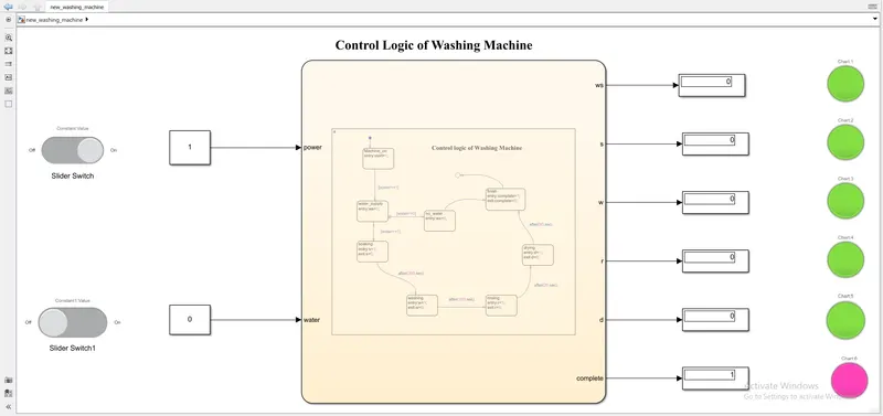
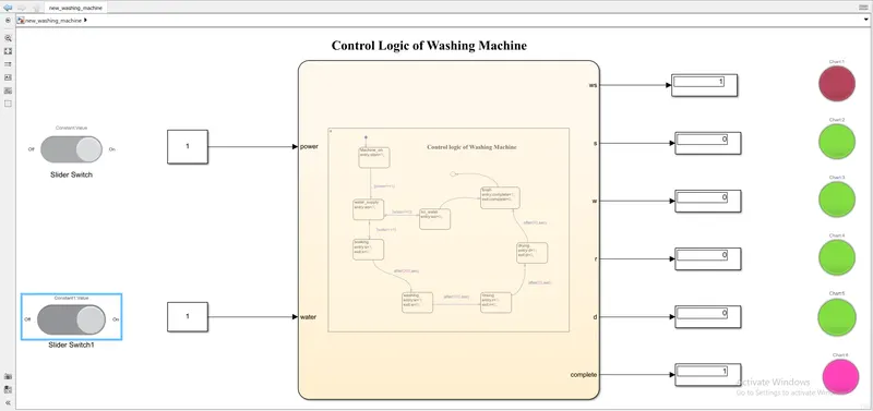
- From above we can see that there are two inputs and six outputs.
Output:
We will get three output for three different conditions, which are
#1: Both power and water supply is off
#2 power supply is on and water supply is off
#3 both power supply and water supply is on
#Part-2:
Make a Simulink chart for the 'Gear shift' logic.
There is some condition for grat shift, which are
Speed Range(km/h) Gear
0 to 15 1
16 to 25 2
26 to 40 3
41 to 60 4
Above 61 5
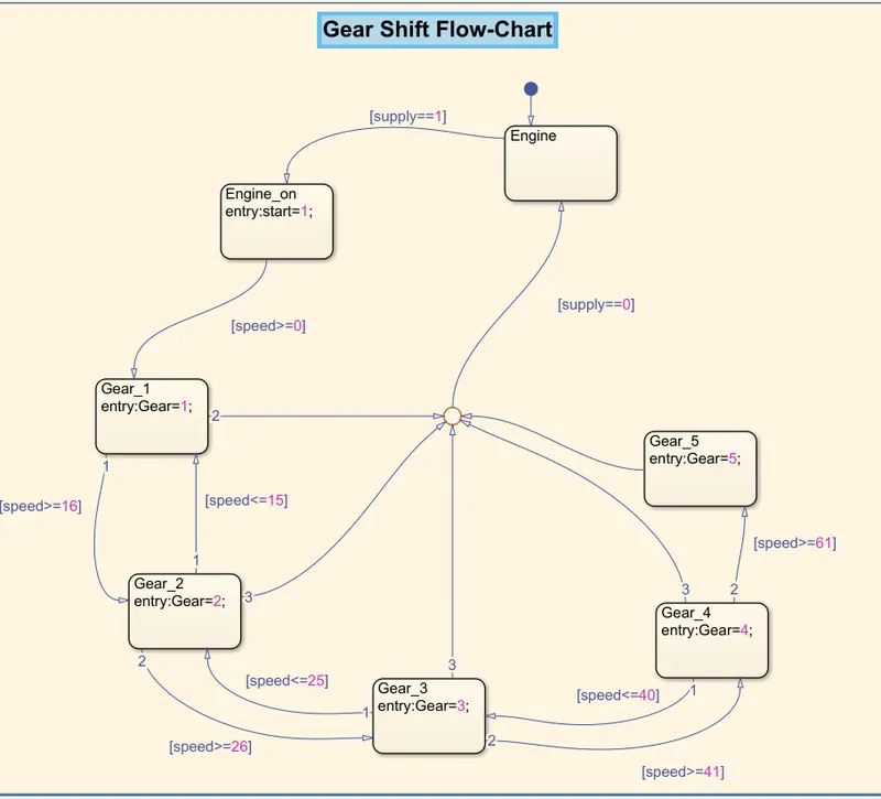
Flow-Chart:
Procedure:
The Flow-Chart explains step by step as follows
- First, add the Engine block with the condition 'supply==1', which provides supply to the Engine. Which helps to start the engine.
- Then add another block to define different gear with their speed condition.
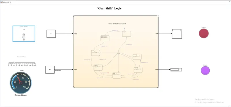
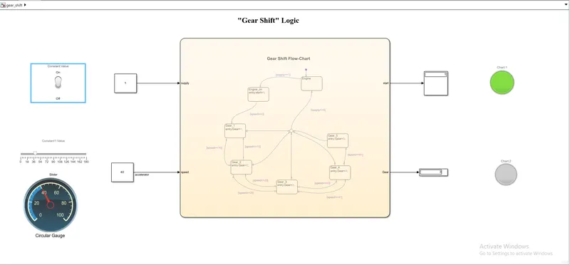
- There are two inputs i.e "supply and speed" and two outputs i.e "start and Gear" for the "Gear Shift" logic.
- To give supply input add "Toggle Switch" and connect it to 'constant'.
- To give speed input add "Slider and Circular Gauge" and connect it to 'constant'.
We will check the output for two conditions.
# Condition 1: The supply is off.
# Condition 2: The supply is on.
Conclusion:
In this way, we use State Flow-Charts to get output for "Washing Machine" and "Gear Shift".